Page is loading ...

INSTALLATION AND REFERENCE MANUAL
UL 325 & UL 991

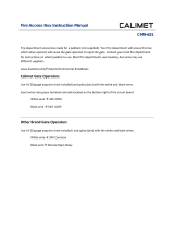
25. Alarm Piezo Buzzer 27. RPM/Position
Sensor
28. Large Pulley
31. Small Pulley
29. Micro V Drive Belt
35. Limit Target Sensor
(Pickle Sensor)
34. Limit Target Sensor Mount
(plastic)
37. AC and Battery Charger
Power Switch
38. DC and Drive Motor Power
Switch
39. 115V / 3 Amp Convenience
Outlets
40. Access Cover for AC Power
Connection
32. Two, 12V, 7AH
Batteries
Additional Parts
www.hysecurity.com • 1-800-321-9947
Side View A
Side View B
26. Cover, Plexiglas
over Control Board
Enclosure
33. Limit Target (Pickle)
41. SlideWinder 24: two 40 ft cables
42. SlideWinder 38: two 62 ft cables
43. SlideWinder 38 backmounted: two 80 ft
cables
Serial # & Model
30. Drive Belt Cover (not
pictured)
24. Motor, SlideWinder 24
1/2 hp, 3-Phase
23. Motor, SlideWinder 38
1 hp, 3-Phase
47. Cable Crimp Tool
(optional)
See complete parts list on inside back cover
45. Gate Attachment Kit
(2) Cable Brackets
(2) Eye bolts with washers
and nuts
(2) Cable Collars
44. Photo Eye Mounting
Brackets
(one for each direction)
36. Reducer,
Gearbox
46. Cable Cutters
(optional)
48. Optional Heavy Duty
Batteries + Wiring Harness
12V AGM 110 AH,
(for extended DC operation,
requires 2 batteries and base
riser)
49. Warning Sign kit
Gate Plackards &
wire ties

Having equipment and installation details on hand can be
helpful if you ever need assistance with SlideWinder
operation, maintenance or service.
Model [ ] 1/2 hp [ ] 1 hp
Serial Number of SlideWinder gate operator___________
(Note: You’ll need this serial number to receive
SlideWinder’s 5-year Warranty support)
Owner’s Name___________________________________
Installation Address_______________________________
City______________________State__________Zip_____
Location of this unit on site _________________________
________________________________________________
Installation
company______________Phone____________
Installation date___________________________________
Installer _________________________________________
Be sure to register this SlideWinder Operator. Complete
and send in the Warranty Card included with this unit.
Refer to the back of this manual for warranty and service
Complete and Keep

19. Cable Drum 1-hp
SlideWinder 38
20. Cable Drum 1/2- hp
SlideWinder 24
21. Motor Mounting Bolts
22. Belt Tensioning Spring,
Bolt & Nut
7. Chassis (front view)
12. Smart Touch Membrane Switch
13. Display Board, LCD
16. Smart Touch Control Board
SlideWinder 24, 1/2 hp
17. Smart Touch Control Board
SlideWinder 38, 1 hp
14. HY-5A Vehicle Detector
(optional)
10. Terminal Board
9. Drive Board
1 hp
SlideWinder 38
Handgrip
Hole for optional cover locking
device
Wiring Entry Holes
6. Polyethylene Mounting Base
(not used with base riser)
11. 12V DC Accessory
Power Supply Board
(optional)
Front Back
Cover
15. Clock Battery, Lithium on
Smart Touch Control Board
5. Base Riser Kit (12”) (optional)
includes stiffener (not pictured)
8. Drive Board
1/2 hp - SllideWinder 24
See complete parts list on inside back cover
www.hysecurity.com • 1-800-321-9947
SlideWinder Parts
2. Cover Mounting Bolt
3. Reset Button
4. Cover Locking kit
(optional)
1. High Impact Polyethylene Cover
18. 56V 500 VA
Transformer
Radio Receiver
Mounting Holes
Circuit Breakers
(top of transformer)
(located
behind gold
mountiing
base)

www.hysecurity.com 1
This handbook is not just part of an exciting
new gate operator, but represents the
realization of a signifi cant new HySecurity
personal vision. HySecurity’s engineers dreamed
and debated how to create a quality operator,
designed from the ground up to address
signifi cant but unmet customer needs. After years
of team building, engineering, testing, failures,
patience, commitment, and dare I say, lots of
cash, the SlideWinder you purchased was born.
I sometimes ask; “If we had understood the
technical diffi culty and resource challenges
we’d face, would we have had the guts to tackle
SlideWinder?” I don’t know that answer, but can
certainly say that SlideWinder happened only
because the company’s vision remained clear
and strong, carrying us through the gigantic
hurdles it takes to create a product which is such
a revolutionary departure from the traditional
chain driven machines.
A message from the President

2 www.hysecurity.com
Introduction
Cable Drive, UPS Backup Slide Gate Operator
SlideWinder is a cable-winch slide gate operator using a 5/32”
stainless steel cable to move the gate. SlideWinder’s stainless
steel cables are attached to a winch, can’t slip and won’t rust.
SlideWinder is powered by an ultra-reliable, variable speed, low
voltage, 3-phase motor. It uses ANY single phase incoming power,
115 V, 208 V, 230 V, 50 or 60 Hz. which is converted to 24 V DC to
charge the batteries and then synthesized into 3-phase AC to power
the motor. This provides SlideWinder’s super-precise positioning (a
few tenths of an inch) and SlideWinder’s graceful start-up and stop.
UPS Backup (not open and die!)
SlideWinder’s unique Uninterruptible Power Supply (UPS) keeps
your automated gate running for 1,000 feet of gate travel (depending
on size/weight of gate and accessory power requirements) using its two
standard 12 V batteries. Adding heavy duty batteries in SlideWinder’s
12” base riser adds 35,000 or more feet of gate travel after an AC power
outage.
Continuous operation after power failure is a signifi cant advantage
over traditional “Open and Die” battery backup systems that leave
your perimeter unsecured upon losing AC power. SlideWinder allows
installers to power all access controls and accessories from its onboard
batteries.
Introducing SlideWinder

www.hysecurity.com 3
Introduction
Unchain yourself
SlideWinder is Simple, Reliable, Secure and Elegant, doing away
with the Achilles Heel of most electromechanical operators: the ugly,
open-to-the-elements, stretching, maintenance prone chain, replacing
it with the simple, clean, no maintenance, rust free stainless steel cable.
Step ten feet away from your gate and the cable virtually disappears.
Accessory compatibility
SlideWinder Slide Operators are fully compatible with all standard
access control devices and entrapment protection devices, some of
which are listed next.
Operator and parts sales
HySecurity sells operators, accessories and replacement parts
through its nationwide network of authorized distributors. Your
HySecurity distributor may be found by calling the company which
installed your SlideWinder or by calling HySecurity directly at
800-321-9947.
Warranty replacement or repair
HySecurity distributors provide extensive warranty service
to HySecurity purchasers through their installation companies.
Contact your HySecurity installer to get quick and effi cient
warranty response.
On the web
For the latest information on HySecurity products, visit us at
www.hysecurity.com.

4 www.hysecurity.com
Introduction
HySecurity’s nationwide distributor and installer network
provide quick and professional installation and technical
support for all HySecurity operators.
Lift the operator cover to display the label (shown at
left) which lists your installer. Many installers add their own
company label to this manual and your operator.
Call HySecurity at 800-321-9947 to locate your installer or
distributor.
You get nationwide installation and
technical support
This is the safety alert symbol. It is used to
alert you to potential personal injury hazards.
Obey all safety messages that follow this
symbol to avoid possible injury or death.
Technical Support

www.hysecurity.com 5
Contents
INTRODUCTION
Parts ............................................Inside front & inside back covers
Message from the President ...........................................................1
Introducing SlideWinder ......................................................... 2 - 3
Technical support ...........................................................................4
Models ............................................................................................6
SAFETY
Safety for installers ................................................................ 7 - 13
Secondary pedestrian entrapment sensors ......................... 14 - 15
Safety for owners ................................................................. 17 - 20
INSTALLATION
Step by step ...................................................................................25
Pads & conduits
Pour pad and mount SlideWinder .......................................26
Conduit locations .................................................................27
Conduit locations with base riser ........................................28
Conduit locations with base riser and HD batteries ...........29
Mechanical adjustments
Belt tension ............................................................................30
Power specifi cations and connections .........................................31
User class and handing
UL User Classes .....................................................................32
Set User Class ........................................................................33
Determine gate handing .......................................................34
Set gate handing ....................................................................35
Installing Brackets and Cables
Overview .......................................................................... 36-37
Temporarily attach leading edge gate bracket .....................38
Temporarily attach trailing edge gate bracket .....................39
Attach leading edge cable to drum and gate bracket .. 40 - 42
Attach trailing edge cable to drum and gate bracket ... 43 - 44
Finished bracket/cable installation diagram ................ 44 - 45
Never Forget Limits
Set close limit ........................................................................47
Set open limit ................................................................ 47 - 48
Erase & re-learn limits ..........................................................48
Attach & learn limit target (Pickle) ......................................49
REFERENCE
Smart Touch controller .................................................. 55 -68
DC operation ................................................................ 71 - 74
Sensors ........................................................................... 77 - 82
Vehicle detectors, loops, diagnostics ............................ 83 - 90
Accessories, other .......................................................... 93 - 94
Dual gate ................................................................................95
Highly secure installations ....................................................96
TROUBLESHOOTING ....................................................................99 - 103
MAINTENANCE ...............................................................................99 - 103
PRODUCT LINE ..............................................................................106 - 107
LIMITED WARRANTY ........................................................................... 108
PARTS ........................................................ Inside front & inside back covers
www.hysecurity.com 5

6 www.hysecurity.com
Introduction
Available models
½ HP
125 lb. pull force
1,200 lb maximum gate weight
24’ maximum gate travel*
UL Class I-IV
115 volts single phase / 6 amps
208 - 230 volts single phase 3.1 - 3 amps
50 or 60 Hz.
SlideWinder Models
1 HP
200 lb. pull force
2,000 lb maximum gate weight
38’ maximum gate travel*
UL Class I-IV
115 volts single phase / 6 amps
208 - 230 volts single phase 3.1 - 3 amps
50 or 60 Hz.
SlideWinder 24 SlideWinder 38
* Minimum gate travel is 10’. SlideWinder cannot be programed to move a gate less than 10’ and not greater than the maximum gate
travel for that model.
Future Models
SlideWinder 24F Fast Installer adjustable variable speed version up to 2’/sec. on SlideWinder 24 UL Class I-IV for speeds up to 1’/sec.;
UL Class III-IV for speeds above 1’/sec.
SlideWinder 24S Solar Solar powered version of SlideWinder 24 UL Class I-IV
SlideWinder 24FS Fast Solar Fast (up to 2’/sec.) solar powered version of SlideWinder 24F UL Class I-IV for speeds up to 1/sec.;
UL Class III-IV for speeds above 1’/sec.
SlideWinder 38F Fast Installer adjustable variable speed version up to 2’/sec. on SlideWinder 38 UL Class I-IV for speeds up to 1/sec.;
UL Class III-IV for speeds above 1’/sec.
SlideWinder 38VF Very Fast Installer adjustable variable speed version (up to 3’/sec.) on SlideWinder 38 UL Class I-IV for speeds up to 1’/sec;
UL Class III-IV for speeds above 1’/sec.
SlideWinder 38S Solar Solar powered version of SlideWinder 38 UL Class I-IV
SlideWinder 38FS Fast Solar Fast (up to 2’/sec.) solar powered version of SlideWinder 38F UL Class I-IV for speeds up to 1’/sec;
UL Class III-IV for speeds above 1’/sec.

www.hysecurity.com 7
Installer Safety
Safety for Installers
INSTALLER SAFETY
Automatic gate operators provide user convenience and
security. However, because these machines can produce high
levels of force, it is imperative that gate operator system designers,
installers and end users be aware of potential hazards associated
with improperly designed, installed or maintained systems. The
gate operator is only one component of the total gate operating
system. It is the joint responsibility of the specifi er, designer,
purchaser, installer and end user to verify that the total system is
appropriately confi gured for its intended use.
Additionally, certain municipalities have established licensing,
codes or regulations that regulate automated gate system design
and installation. Consult local government agencies for up-to-date
rules and regulations prior to gate system design or installation.
Before completing installation, be certain to
provide owners and users the Safety Information
on pages 17 - 20.
Underwriter Laboratories (UL) and the American Society for
Testing and Materials (ASTM) are responsible for many current
regulations regarding gate operators and automated gates. These
standards are revised periodically. Go to www.ul.com for the most
up-to-date UL 325 gate operator standard. Go to www.astm.org for
the most up-to-date ASTM F2200 gate and fence standard.
MANDATORY
Review before gate system design
or installation

8 www.hysecurity.com
Installer Safety
Use this list of primary considerations before
and after installation to make sure your SlideWinder
installation meets UL 325 and ASTM F2200 Standard
requirements. For a latest edition copy of operator
and gate standard requirements, see www.ul.com and
www.astm.org.
Make Sure the Gate Operator Usage Class is Correct for the Site and Type of Gate
WARNING
A moving gate can cause serious injury or death.
Read and follow all Installation Manual, Reference
Manual and Warning Label instructions.
SlideWinder meets all UL listing Class requirements
Safety for Installers
Review this important
information thoroughly before
you install anything
Class I
Intended for use in a home of one
to four single family dwellings, or
a parking area associated with a
one to four single family dwelling.
Class II
Intended for use in a commercial location
or building such as a multi-family
housing unit (fi ve or more single family
units) hotel, garages, retail store or other
buildings servicing the general public.
Class III
Intended for use in an industrial location
or building such as a factory or loading
dock or other locations not intended to
service the general public.
Class IV
Intended for use in a guarded industrial
location or building such as an airport
security area or other restricted access
locations not servicing the general public, in
which unauthorized access is prevented via
supervision by security personnel.

www.hysecurity.com 9
Installer Safety
Sliding gate operators installed in Class I & II applications must not move
the gate faster than one foot per second. Operators in class III and IV do
not have a speed restriction. SlideWinder must be installed and confi gured
to meet the UL user classifi cation.
The automated entry must be for vehicles only. Pedestrians must
be directed to a separate walk-through entrance.
Gate Speed Must Meet UL Speed Restriction
No Pedestrian Use
Safety for Installers
INSTALLER SAFETY
Make sure the gate moves freely in BOTH directions. A gate
that moves easily reverses with less contact force.
Gate Moves Freely

10 www.hysecurity.com
Installer Safety
Do not install an automatic operator on a gate not in compliance with
the latest ASTM F2200 Standard. Provide guards and/or screening of any
openings from the bottom of the gate to at least 4 feet (1.2 m) above the
ground, to prevent a sphere 2¼ inches (57 mm) in diameter from passing
through an opening anywhere in the gate or the portion of the adjacent
fence that is covered in the open position. Gate may be screened as in
illustration, or gate may have 2” or less space between pickets. All openings
between 48” and 72” above grade must be small enough to prevent a 4”
sphere from passing through the opening.
Never install access control devices within reach of gate. People
attempting to use the operator can be seriously injured or killed by
the moving gate. See below for proper access control placement.
Install the operator inside the gate on the secured (non-public) side so that
only authorized users can touch or access any part of it. Gate operating controls
must be mounted far enough away from the moving gate (6-feet minimum)
such that users cannot touch the gate while operating controls. All easily
accessible controls must have a security feature to prevent unauthorized use.
Gate pickets must be placed at
4” or less centers.
All gate openings
from ground to 4’
high must be less
than 2-1/4”.
Safety for Installers
Never Install Access Control Devices Within
Reach of Gate
Operator Mounted on Secure Side of Gate
Screen or Enclose Openings in Gate

www.hysecurity.com 11
Installer Safety
Check electrical ground and AC power supply.
The operator must be properly grounded and intended
supply voltage must match the voltage label on the operator.
SlideWinder operates using any SINGLE PHASE AC power.
The Open and Stop inputs also perform a reset function
and must be located such that the user will have a clear view
of the gate. Connect radio and other remote access, non-
reset controls only to the Remote Open input (Smart Touch
Controller Terminal #4 ).
Safety for Installers
INSTALLER SAFETY
Install physical stops to prevent over-travel in both
directions and guard posts to prevent the gate from falling
if a roller fails.
OUTLETS
115V 3 AMP Max
DISCONNECT FROM
POWER PRIOR TO SERVICE
Supply: 115V/208-230V 1Ø 50 - 60 HZ
6/3.1-3 Amps
Use Only Copper Conductors with Temp Rating of 75° C
High Voltage Inside
Locate Reset Controls Where User Has
Clear View of Gate
Install Physical Stops
Incoming Power Matches Operator Voltage

12 www.hysecurity.com
Installer Safety
Carefully review this guide’s instructions for placement, installation
and adjustment of these sensors. External entrapment protection
sensors must reverse gate while opening AND closing. If edge
(contact) sensors are used, mount them on both leading and trailing
gate edges, as well as on any posts on the inside and outside of the
gate. If photo eyes or other non-contact sensors are used, mount
them as close as possible to the gate where they can best guard
against entrapment. You can use a combination of contact and non-
contact sensors, but all must be recognized components under the
UL 325 standard. See pages 14 - 15 and 77 - 82 for more details on
these and other requirements.
Verify that you have covers installed on all exposed gate
support wheels to prevent pinch points. Insure that the entire
gate installation meets ASTM exposed pinch point spacing
requirements. For full details, look up the latest ASTM F2200
Standard Specifi cation for Automated Vehicular Gate Construction
at www.astm.org.
Install the warning signs supplied with Slidewinder on the
INSIDE and OUTSIDE of Gate so they are clearly visible
from both sides of the gate.
Safety for Installers
Install Warning Signs
Install External Entrapment Sensors
Install Mechanical Guards on All Exposed
Pinch Points, Rollers and Wheels

www.hysecurity.com 13
Installer Safety
INSTALLER SAFETY
The ASTM F2200 standard dictates that automated slide gates
not be installed in a manner that could allow a gate to run
away in an open or closed direction. This standard requires
that in order to be compliant, any automated slide gate must
be nearly level.
Don’t Install Slide Gate Operator Where
Gate Will Move Up or Down Hill
Safety for Installers

14 www.hysecurity.com
Installer Safety
Automatic gate operators are intended only for vehicular use
and pedestrians must be routed to a separate pedestrian gate.
However, sensors are still required in order to provide a degree of
protection should anyone stray into the area of an automatic gate.
Generally there are two types of external sensors that may be used:
Contact sensors, such as edge sensors, and non-contact sensors,
such as photoelectric eyes. Current industry standards require the
use of either type or both of these sensors, as a secondary device in
Class I and Class II automatic sliding gate installations, because the
general public is likely to be present. Although there are alternatives
for Class III and IV installations, HySecurity highly recommends
the use of external sensors for all automatic gate applications.
The specifi er or installer may choose either photoelectric
eyes or edge sensors, or use these devices in combination, but
protection in both the open and closing directions of gate travel
must be provided. The UL 325 standard for automatic sliding gates
specifi cally requires the following:
PHOTOELECTRIC EYES One or more non-contact sensors
(photoelectric eyes) shall be located where the risk of
entrapment or obstruction exists, such as the perimeter
reachable by a moving gate.
CONTACT SENSORS One or more contact sensors (edge sensors)
shall be located at the leading edge, trailing edge and post(s)
mounted both inside and outside of a sliding gate.
CONTACT SENSOR SECURITY A hardwired contact sensor shall
be located and its wiring arranged so that communication
between the sensor and gate is not subjected to mechanical
damage.
CONTACT SENSOR COMMUNICATION A contact sensor that
transmits its signal to the gate operator shall be located such
that the signal is not impeded by building structures or other
obstructions and shall function under its intended end-use
conditions.
UL 325 LISTING The contact and non-contact sensors must be
tested and labeled as “Recognized Components” under the UL
325 standard in order to be deemed acceptable for use in this
application.
Study safety illustrations in this manual’s Installation section
and consider your specifi c installation to determine where greatest
entrapment risks exist. Locate edge sensors and/or photoelectric
sensors accordingly. Be certain that a suffi cient number of sensors
are used so that both directions of gate travel are properly guarded.
Go to www.ul.com for the most up-to-date list of gate operator
Underwriter Laboratory standards (UL 325). Go to www.astm.org
for a complete list of ASTM F2200 gate and fence standards.
Underwriter Laboratories (UL) and the American Society for
Testing and Materials (ASTM) are responsible for many current
regulations regarding gate operators and automated gates. These
standards are revised periodically. Go to www.ul.com for the most
up-to-date UL 325 gate operator standard. Go to www.astm.org for
the most up-to-date ASTM F2200 gate and fence standard.
Secondary pedestrian entrapment sensors
WARNING: To reduce the risk of serious injury
or death, read and follow all Installation Manual,
Reference Manual and Warning Label instructions.
Safety for Installers

www.hysecurity.com 15
Installer Safety
Gate Operator Category
Horizontal Slide Swing Vertical
Vertical Lift Barrier (arm)
Vertical Pivot
Note: The same type of device shall not be utilized for both primary and secondary entrapment protection. Use of a single device for
both the opening and closing directions is in accordance with the requirement. However a single device is not required to cover both
directions. A combination of one Type B1 for one direction and one Type B2 for the other direction is the equivalent of one device and
is in compliance with the requirements of either primary or secondary of entrapment protection.
Usage class Primary*Secondary*Primary*Secondary*
Vehicular I and II A B1, B2, or D A, or C A, B1, B2, C, or D
Vehicular III A, B1, or B2 A, B1, B2, D, or E A, B1, or C A, B1, B2, C, D, or E
Vehicular IV A, B1, B2, or D A, B1, B2, D, or E A, B1, C, or D A, B1, B2, C, D, or E
*Entrapment protection sensor types:
Type A Inherent entrapment sensing systems.
Type B1 A non-contact sensor (photoelectric sensor or equivalent).
Type B2 A contact sensor (edge sensor device or equivalent).
Type C Inherent adjustable clutch or pressure relief device.
Type D An actuating device requiring continuous pressure to maintain opening or closing motion of the gate.
Type E An inherent audio alarm, which warns a minimum of 3 seconds before operation.
Go to www.ul.com for the most up-to-date UL 325 gate operator standard. Go to www.astm.org for the most up-to-date ASTM F2200
gate and fence standard.
UL 325 standards for entrapment protection devices
INSTALLER SAFETY
Safety for Installers

16 www.hysecurity.com
Notes
/