
www.dell.com | support.dell.com
Dell™ Systems
Installing the 1 x 2 SCSI
Module
安装 1 x 2 SCSI 模块
Installation du module SCSI 1 x 2
Installation des 1 x 2-SCSI-Moduls
1 x 2 SCSI モジュールの取り付け
1 x 2 SCSI 모듈 설치
Instalación del módulo SCSI 1 x 2
F6590bk0.book Page 1 Tuesday, July 6, 2004 4:33 PM

F6590bk0.book Page 2 Tuesday, July 6, 2004 4:33 PM

www.dell.com | support.dell.com
Dell™ Systems
Installing the 1 x 2 SCSI
Module
F6590bk0.book Page 1 Tuesday, July 6, 2004 4:33 PM

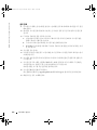
Notes, Notices, and Cautions
NOTE: A NOTE indicates important information that helps you make better use of your computer.
NOTICE: A NOTICE indicates either potential damage to hardware or loss of data and tells you how to avoid
the problem.
CAUTION: A CAUTION indicates a potential for property damage, personal injury, or death.
____________________
Information in this document is subject to change without notice.
© 2004 Dell Inc. All rights reserved.
Reproduction in any manner whatsoever without the written permission of Dell Inc. is strictly forbidden.
Trademarks used in this text: Dell and the DELL logo are trademarks of Dell Inc.
Other trademarks and trade names may be used in this document to refer to either the entities claiming the marks and names
or their products. Dell Inc. disclaims any proprietary interest in trademarks and trade names other than its own.
July 2004 P/N F6590 Rev. A00
F6590bk0.book Page 2 Tuesday, July 6, 2004 4:33 PM

Installing the 1 x 2 SCSI Module 1-3
This document provides instructions for installing a 1 x 2 module kit to add support for up to
two additional 1-inch SCSI hard drives in your system’s peripheral bay. This kit contains the
following items:
• 1 x 2 SCSI module and backplane
• Power cable harness
• SCSI cable(s)
• Guide rails (2)
• 4 x 6-32 screws
CAUTION: Before you perform this procedure, read the safety instructions in your Product Information
Guide.
CAUTION: Only trained service technicians are authorized to remove the system cover and access any
of the components inside the system. See your Product Information Guide for complete information
about safety precautions, working inside the computer, and protecting against electrostatic discharge.
NOTICE: To avoid data loss, back up all data on the hard drives before installing the backplanes
and changing the drive configuration.
NOTE: See your Installation and Troubleshooting Guide for detailed instructions on removing or
replacing components.
Before You Begin
NOTICE: Before you install the backplane, update the BIOS to the latest version.
Before you shut down the system to install the backplane:
1
Record the system configuration settings.
View the system configuration screens in the System Setup program and make a record of
these settings. See your
User’s Guide
for instructions on using the System Setup program.
2
Update the BIOS.
See the Dell Support website at
support.dell.com
for the latest BIOS version for your system.
Installing the 1 x 2 Module
1
Remove the front bezel (if applicable).
2
Turn off the system, including any attached peripherals, and disconnect the system from
the electrical outlet.
3
If your system is installed in a rack, go to step 4.
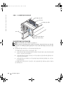
If you have a standalone system, locate a flat, nonconductive surface, remove the stabilizers,
and lay the system on its side, as shown in Figure 1-1.
4
Open the system.
F6590bk0.book Page 3 Tuesday, July 6, 2004 4:33 PM

1-4 Installing the 1 x 2 SCSI Module
www.dell.com | support.dell.com
5
Slide the drive tray to the maintenance position.
a
Use a #2 Phillips screwdriver to loosen the captive screw that secures the drive tray
release handle to the chassis.
b
Rotate the drive tray release lever toward the front of the system.
c
Grasp both sides of the front panel and slide the drive tray towards the front of the
system until the tray is in the maintenance position.
Installing the Drive Cage
1
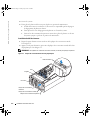
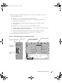
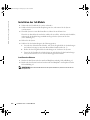
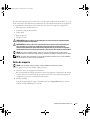
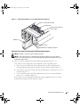
Locate the insert tab above the center filler plate. See Figure 1-1.
2
Press the insert tab and remove the center filler plate from the peripheral bay. See Figure 1-1.
NOTE: If a tape drive is not installed in your system, do not remove the top filler plate.
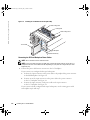
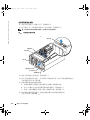
Figure 1-1. Peripheral Bay Filler Plates
3
Locate the black square on the lower filler plate. See Figure 1-1.
4
Place your right thumb on the black square, reach behind the lower filler plate, squeeze
the lower filler plate release lever, and remove the filler plate from the peripheral bay.
center filler plate
top filler plate
lower filler plate
insert tab
black square
thumbscrew
cam handle
F6590bk0.book Page 4 Tuesday, July 6, 2004 4:33 PM

Installing the 1 x 2 SCSI Module 1-5
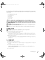
5
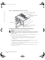
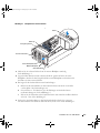
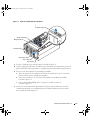
Attach the drive rails to the drive cage.
a
Align the screw holes on the drive rails with the screw holes located near slot 1
on the drive cage.
b
Insert the 6 x 32 screws (4) into the drive rails and drive cage. See Figure 1-2.
c
Use a #2 Phillips screwdriver to tighten the screws on each rail. See Figure 1-2.
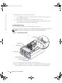
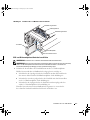
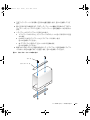
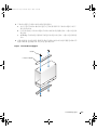
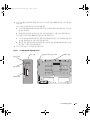
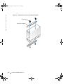
6
With the power connector pointing towards the top of the system, insert the drive cage
into the peripheral drive bay until it snaps into place. See Figure 1-3.
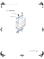
Figure 1-2. Installing the Drive Cage Rails
drive rails (2)
screws (4)
F6590bk0.book Page 5 Tuesday, July 6, 2004 4:33 PM

1-6 Installing the 1 x 2 SCSI Module
www.dell.com | support.dell.com
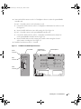
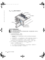
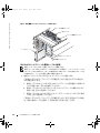
Figure 1-3. Installing the 1 x 2 Module Into the Peripheral Bay
Connecting the SCSI and Backplane Power Cables
NOTE: The 1 x 2 drive 0 functions as the boot drive.
NOTE: If your kit contains more than one SCSI cable, use the appropriate cable to connect the 1 x 2
backplane to the riser card or RAID controller. Depending on your particular configuration, the cable
length may vary.
1
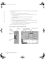
Connect the power cable harness connectors to the 1 x 2 backplane.
If your system is not configured with a tape backup unit:
a
Connect the 14-pin connector on the power cable to the peripheral bay power connector
on the SCSI backplane. See Figure 1-4.
b
Connect one of the 4-pin connectors on the power cable to the power connector
on the 1 x 2 backplane. See Figure 1-4.
c
Connect the 6-pin connector on the power cable to the 6-pin connector
on the 1 x 2 backplane. See Figure 1-4.
If your system is already configured with a tape backup unit, use the existing power cable
and complete step b and step c.
1 x 2 module
peripheral drive bay
top filler plate
cable routing slot 2
cable routing slot 1
cooling fan 8
F6590bk0.book Page 6 Tuesday, July 6, 2004 4:33 PM

Installing the 1 x 2 SCSI Module 1-7
2
Connect the SCSI connector on the 1 x 2 backplane to the riser card or the optional RAID
controller card.
If your 1 x 2 module connects to the onboard riser card:
a
Connect the SCSI connector on the 1 x 2 backplane to SCSI channel A on the riser card.
See Figure 1-4.
b
Insert the SCSI cable harness into cable routing slot 1. See Figure 1-4.
If your 1 x 2 module connects to the optional RAID controller card:
a
Connect the SCSI connector on the 1 x 2 backplane to SCSI channel A (channel 0)
on the optional RAID controller card. See Figure 1-4.
b
Insert the SCSI cable into cable routing slot 2 and the cable routing slots located
at the bottom of cooling fan 8. See Figure 1-3.
3
Install the hard drives into the 1 x 2 module.
Figure 1-4. 1 x 2 Module and SCSI Backplane Connectors
peripheral bay
power connector
power
connector
6-pin
connector
SCSI
connector
1 x 2 module
SCSI backplane
F6590bk0.book Page 7 Tuesday, July 6, 2004 4:33 PM

1-8 Installing the 1 x 2 SCSI Module
www.dell.com | support.dell.com
Completing the Installation
1
Check all cable connections that may have been loosened during the procedure.
2
Arrange the cables so that they do not catch on the system cover or block the airflow
of the fans or the cooling vents.
3
Slide the drive tray to the operating position.
a
Grasp both sides of the front panel and slide the drive tray towards the back of the system
until the tray is in the operating position.
b
Rotate the drive tray release lever toward the back of the system.
c
Use a #2 Phillips screwdriver to tighten the captive screw that secures the drive tray
release handle to the chassis.
4
Close the system.
5
If you have a standalone system, reinstall the stabilizers and place the system in the upright
position (if applicable).
6
Reconnect the system to its electrical outlet and turn the system on, including any attached
peripherals.
7
Enter System Setup to ensure that the RAID or SCSI controller card is configured correctly.
You may also need to verify the correct boot order.
See your system
User’s Guide
for more information.
8
Update the system firmware.
See the Dell Support website at
support.dell.com
for the latest firmware updates.
9
Replace the bezel (if applicable).
F6590bk0.book Page 8 Tuesday, July 6, 2004 4:33 PM

www.dell.com | support.dell.com
Dell™ 系统
安装 1 x 2 SCSI 模块
F6590cbk0.book Page 1 Tuesday, July 6, 2004 4:05 PM
Page is loading ...
Page is loading ...
Page is loading ...

安装 1 x 2 SCSI 模块 2-5
图
2-2.
安装驱动器托架滑轨
驱动器滑轨(2 根)
螺钉(4 颗)
F6590cbk0.book Page 5 Tuesday, July 6, 2004 4:05 PM
Page is loading ...
Page is loading ...
Page is loading ...

www.dell.com | support.dell.com
Systèmes Dell™
Installation du module
SCSI 1 x 2
F6590fbk0.book Page 1 Tuesday, July 6, 2004 4:36 PM
Page is loading ...
Page is loading ...
Page is loading ...
Page is loading ...
Page is loading ...
Page is loading ...
Page is loading ...

www.dell.com | support.dell.com
Dell™-Systeme
Installation des
1 x 2-SCSI-Moduls
F6590gbk0.book Page 1 Tuesday, July 6, 2004 4:38 PM
Page is loading ...
Page is loading ...
Page is loading ...
Page is loading ...

4-6 Installation des 1 x 2-SCSI-Moduls
www.dell.com | support.dell.com
Abbildung 4-2. Installieren der Laufwerkträgerschienen
Laufwerksschienen (2)
Schrauben (4)
F6590gbk0.book Page 6 Tuesday, July 6, 2004 4:38 PM
Page is loading ...
Page is loading ...
Page is loading ...

4-10 Installation des 1 x 2-SCSI-Moduls
www.dell.com | support.dell.com
F6590gbk0.book Page 10 Tuesday, July 6, 2004 4:38 PM

www.dell.com | support.dell.com
Dell
™
システム
1
×
2 SCSI
モジュールの取り付け
F6590jbk0.book Page 1 Tuesday, July 6, 2004 4:47 PM
Page is loading ...
Page is loading ...
Page is loading ...
Page is loading ...
Page is loading ...
Page is loading ...
Page is loading ...

www.dell.com | support.dell.com
Dell™ 시스템
1 x 2 SCSI 모듈 설치
F6590kbk0.book Page 1 Monday, July 5, 2004 3:21 PM
Page is loading ...
Page is loading ...
Page is loading ...
Page is loading ...
Page is loading ...
Page is loading ...
Page is loading ...

www.dell.com | support.dell.com
Sistemas Dell™
Instalación del módulo
SCSI 1 x 2
F6590sbk0.book Page 1 Tuesday, July 6, 2004 4:55 PM
Page is loading ...
Page is loading ...
Page is loading ...
Page is loading ...

7-6 Instalación del módulo SCSI 1 x 2
www.dell.com | support.dell.com
Figura 7-2. Instalación de los rieles de la canastilla para unidades
Rieles de la unidad (2)
Tornillos (4)
F6590sbk0.book Page 6 Tuesday, July 6, 2004 4:55 PM
Page is loading ...
Page is loading ...
Page is loading ...
Page is loading ...
Page is loading ...
Page is loading ...
-
 1
1
-
 2
2
-
 3
3
-
 4
4
-
 5
5
-
 6
6
-
 7
7
-
 8
8
-
 9
9
-
 10
10
-
 11
11
-
 12
12
-
 13
13
-
 14
14
-
 15
15
-
 16
16
-
 17
17
-
 18
18
-
 19
19
-
 20
20
-
 21
21
-
 22
22
-
 23
23
-
 24
24
-
 25
25
-
 26
26
-
 27
27
-
 28
28
-
 29
29
-
 30
30
-
 31
31
-
 32
32
-
 33
33
-
 34
34
-
 35
35
-
 36
36
-
 37
37
-
 38
38
-
 39
39
-
 40
40
-
 41
41
-
 42
42
-
 43
43
-
 44
44
-
 45
45
-
 46
46
-
 47
47
-
 48
48
-
 49
49
-
 50
50
-
 51
51
-
 52
52
-
 53
53
-
 54
54
-
 55
55
-
 56
56
-
 57
57
-
 58
58
-
 59
59
-
 60
60
-
 61
61
-
 62
62
-
 63
63
-
 64
64


Ask a question and I''ll find the answer in the document
Finding information in a document is now easier with AI
in other languages
- français: Dell PowerEdge 2800 Mode d'emploi
- español: Dell PowerEdge 2800 Guía del usuario
- Deutsch: Dell PowerEdge 2800 Benutzerhandbuch
- 日本語: Dell PowerEdge 2800 ユーザーガイド
Related papers
-
Dell PowerEdge 1850 User manual
-
-
-
-
-
Dell PowerEdge 750 Installation guide
-
-
-
-