
MSAsafety.com
User Instructions
Self-Retracting Lanyard and
Self-Retracting Lanyard with Emergency Rescuer
Model/Modelo/Modèle
Order No./N. º de pedido/Nº de commande : 10088452/14
Print Spec./Especif. impr./Spéc. d'imp. : 10000005389(F)
CR 800000029139
Instrucciones de uso
Cuerda amortiguadora autorretráctil y cuerda amortiguadora
autorretráctil con rescatador de emergencia
Mode d'emploi
Longe Auto-rétractable et
Longe Auto-rétractable avec Dispositif de Sauvetage d’urgence

WARNING
National standards and state, provincial and federal laws require the user to be trained before using
this product. Use this manual as part of a user safety training program that is appropriate for the
user’s occupation. These instructions must be provided to users before use of the product and
retained for ready reference by the user. The user must read, understand (or have explained), and
heed all instructions, labels, markings and warnings supplied with this product and with those
products intended for use in association with it. FAILURE TO DO SO MAY RESULT IN SERIOUS
INJURY OR DEATH.
¡ADVERTENCIA!
Las normas nacionales y las leyes estatales, provinciales y federales exigen que se capacite al
usuario antes de usar este producto. Utilice este manual como parte de un programa de capacitación
sobre normas de seguridad que corresponda a las tareas desempeñadas por el usuario. Estas ins-
trucciones se deben proveer a los usuarios antes de usar el producto y se deben conservar para que
el usuario pueda consultarlas rápidamente. El usuario debe leer, comprender (o solicitar que se le
expliquen) y seguir todas las instrucciones, etiquetas, marcas y advertencias que acompañan a este
producto y a otros productos que se deban usar conjuntamente con el mismo. EL INCUMPLI-
MIENTO DE LO ANTERIOR PODRÍA PROVOCAR LESIONES GRAVES O LA MUERTE.
AVERTISSEMENT !
Les normes nationales ainsi que les lois d’État, fédérales et provinciales exigent que l’utilisateur
reçoive la formation nécessaire avant d’utiliser ce produit. Utiliser ce manuel dans le cadre d’un
programme de formation sur la sécurité correspondant à la profession de l’utilisateur. Ces instruc-
tions doivent être fournies aux utilisateurs avant qu’ils ne commencent à utiliser le produit, et laissées
à leur disposition pour consultation future. L’utilisateur doit lire ou se faire expliquer les instructions,
les étiquettes, les notations et les avertissements relatifs à ce produit et aux produits associés; il doit
bien les comprendre et s’y conformer. TOUTE NÉGLIGENCE À CE SUJET PRÉSENTE UN
RISQUE DE BLESSURE GRAVE OU UN DANGER DE MORT.
1000 Cranberry Woods Drive
Cranberry Township, PA 16066
USA
Phone 1-800-MSA-2222
Fax 1-800-967-0398
For your local MSA contacts please go to our website www.MSAsafety.com
Para conocer los contactos locales MSA, visite nuestro sitio web www.MSAsafety.com
Pour connaître les coordonnées des représentants MSA de votre région,
veuillez consulter notre site Web à l’adresse www.MSAsafety.com
©
MSA 2019. All rights reserved/Todos los derechos reservados/Tous droits réservés

Self-Retracting Lanyard
3
Content
US
Content
1 Safety Regulations ........................................................................................ 5
1.1 Correct Use .......................................................................................... 5
1.2 Usage Specifications............................................................................ 5
1.3 Usage Limitations................................................................................. 5
1.3.1 Physical Limitations.............................................................................. 5
1.3.2 Hazards................................................................................................ 6
1.4 Liability Information .............................................................................. 6
1.5 Safety and Precautionary Measures to be Adopted ............................. 7
1.6 Warranty ............................................................................................... 7
1.7 Owner Registration .............................................................................. 7
2 Description ..................................................................................................... 8
2.1 Component Specifications ................................................................... 8
2.2 Markings and Labels ............................................................................ 8
2.3 System Requirements .......................................................................... 8
2.3.1 Compatibility of Components and Subsystems .................................... 8
2.3.2 Compatibility of Connectors ................................................................. 9
2.3.3 Anchorages and Anchorage Connectors ............................................. 9
3 Use .................................................................................................................. 9
3.1 Planning the Use of Systems ............................................................... 9
3.1.1 Rescue and Evacuation ....................................................................... 9
3.1.2 Fall Arrest Distance .............................................................................. 9
3.1.3 Set Up ................................................................................................ 10
3.1.4 Fall Clearance .................................................................................... 11
3.1.5 Tag Line ............................................................................................. 11
3.2 Making Connections ........................................................................... 11
3.2.1 Anchorage Mounted SRL (not applicable to the
Workman Twin Leg PFL) ................................................................... 11
3.2.2 User Mounted SRL ............................................................................. 11
3.2.3 Backpacker Mount (Backpacker SRL only) ........................................ 11
3.2.4 Workman Twin Leg PFL ..................................................................... 12
3.2.5 Workman Twin Leg PFL Alternate Installation ................................... 13
3.3 Moving around the Work Area ........................................................... 14
3.3.1 Workman Twin Leg PFL Usage ......................................................... 14

US
Content
Self-Retracting Lanyard
4
3.4 Rescue SRLs (Lynx and Dynevac II) ..................................................14
3.4.1 Setting the Rescue SRL to Rescue Mode ..........................................14
3.4.2 Raising and Lowering during Rescue................................................. 14
3.4.3 Resetting the Rescue SRL to Fall Arrest Mode ..................................15
4 Care, Maintenance and Storage ................................................................. 15
4.1 Cleaning .............................................................................................15
4.2 Maintenance and Repairs ...................................................................15
4.3 Transportation ....................................................................................15
4.4 Storage............................................................................................... 15
5 Inspection .....................................................................................................16
5.1 Inspection Frequency .........................................................................16
5.2 Inspection Procedure ..........................................................................16
5.3 Formal Inspection ...............................................................................17
5.4 SRLs with Radio Frequency Identification (RFID) .............................. 18
5.5 Corrective Action ................................................................................18
5.6 Factory Service and Repair ................................................................18
5.7 Inspection and Service Log ................................................................19
Appendix....................................................................................................... 56

Self-Retracting Lanyard
5
Safety Regulations
US
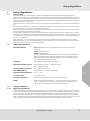
1 Safety Regulations
1.1 Correct Use
The Self-Retracting Lanyard (SRL) and the Self-Retracting Lanyard with Emergency Rescuer
(Rescue SRL) are part of a fall arrest system when attached to the fall arrest attachment of a full body
harness and an appropriate anchorage. See harness instructions for approved attachment points. If a
user falls, the device will automatically stop the user's descent in a short distance while limiting the fall
arrest force on the user's body.
Rescue units also provide an emergency rescue mechanism for retrieval of a user who experienced a
fall.
See instruction labels on the product for capacity of that system. All systems are designed for a single
person, with only one person on the lifeline at any time.
The Self-Retracting Lanyard and the Self-Retracting Lanyard with Emergency Rescuer are intended
for use by trained and qualified personnel.
It is imperative that this manual be read and observed when using the product. In particular, the safety
instructions, as well as the information for the use and operation of the product, must be carefully read
and observed. Furthermore, the national regulations applicable in the user's country must be taken into
account for a safe use.
Alternative use, or use outside this specification will be considered as non-compliance. This also
applies especially to unauthorized alterations to the product and to commissioning work that has not
been carried out by MSA or authorized persons.
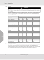
1.2 Usage Specifications
1.3 Usage Limitations
1.3.1 Physical Limitations
The Self-Retracting Lanyard is designed for one user whose weight, including clothing, tools, and other
user-borne objects, is less than the capacity shown on product label. Persons with muscular, skeletal,
or other physical disorders should consult a physician before using the SRL. Pregnant women and
minors must never use the SRL. Increasing age and lowered physical fitness may reduce a person’s
ability to withstand shock loads during fall arrest or prolonged suspension. Consult a physician if there
is any question about physical ability to safely use this product to arrest a fall or suspend.
Meets Standards: US: ANSI Z359.14-2012, class B; OSHA 29 CFR 1910.66 and
1926.502
CAN: CSA Z259.2.2-17
Europe: EN360:2002
Only the standards in the Meets Standards section of the Model label
apply to a specific SRL. SRLs designated with a certification mark
are listed with the corresponding agency as compliant to at least one
of the standards indicated above.
Capacity: See product label for capacity rating.
Maximum Arresting Force: ANSI, OSHA and CSA – 1800 lbs (8 kN)
EN – 1350 lbs (6 kN)
Average Arresting Force:
(per ANSI Z359.14)
Dry – 900 lbs (4 kN) max.
Cold/Hot/Wet – 1125 lbs (5 kN) max.
Maximum Arrest Distance: 47 in. (1.2 m)
Free Fall Limit: 2 ft (0.6 m) max.
Emergency Rescuer: Applies to the Dynevac II and Lynx Rescuers only.
RFID: Radio Frequency Identification – Some products include an RFID
chip for identification and tracking. See section 2.2 Marking and
Labels for the RFID location on applicable products.

US
Safety Regulations
Self-Retracting Lanyard
6
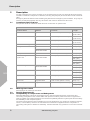
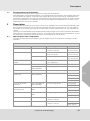
1.3.2 Hazards
Chemical hazards, heat and corrosion may damage the SRL. More frequent formal inspections are
required in environments with chemical hazards, heat and corrosion. Use caution when working
around moving machinery.
* Concentrated sulfuric acid attacks polyester
1.4 Liability Information
MSA accepts no liability in cases where the device has been used inappropriately or not as intended.
The selection and use of the device are the exclusive responsibility of the individual operator.
Product liability claims, warranties and guarantees made by MSA with respect to the device are voided,
if it is not used, serviced or maintained in accordance with the instructions in this manual.
WARNING
Do not expose the line to sharp edges, abrasive surfaces, sparks, flame, or heat above 185 °F
(85 °C).
Do not install or use where device may encounter electrical hazards. Misuse can result in serious
injury or death.
CHEMICAL
RESISTANCE
Nylon Polyester
Stainless Steel
(304)
Galvanized Steel
Strong acid (dilute) Poor Good Fair Poor
Strong acid (conc.) Poor Fair* Poor Poor
Weak acid (dilute) Poor Good Good Poor
Weak acid (conc.) Poor Good Poor Poor
Strong alkali (dilute) Good Poor Good Poor
Strong alkali (conc.) Fair Poor Fair Poor
Weak alkali (dilute) Good Fair Good Fair
Weak alkali (conc.) Good Poor Fair Poor
Alcohol Good Fair Good Good
Aldehyde Good Poor Good Good
Ether Good Poor Good Good
Halogenated Hydrocarbons Good Good Good Good
Phenols Poor Poor Good Good
Bleaching agents Poor Good Fair Poor
Ketones Good Poor Good Fair
Lubricating Oils & Greases Good Good Good Good
Soaps & Detergents Good Good Good Good
Seawater Good Good Fair Poor
Aromatic Solvents Good Poor Good Good

Self-Retracting Lanyard
7
Safety Regulations
US
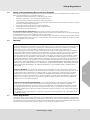
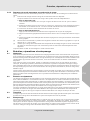
1.5 Safety and Precautionary Measures to be Adopted
Purchasers of MSA Self Retracting Lanyards must ensure that users are familiar with the User Instruc-
tions and are trained by a competent person in:
- workplace hazard identification, evaluation and control
- selection, inspection, use, storage and maintenance
- usage planning including calculation of fall clearances
- compatibility and selection of anchorage and anchorage connectors including connections to help
prevent accidental disengagement
- proper lanyard and harness connection locations
- evacuation and rescue planning and implementation
- consequences of improper use
For Confined Space applications: See OSHA 29 CFR 1910.146 and ANSI Z117.1.
Periodically (at least annually) assess effectiveness of training and determine the need for retraining
or additional training. Contact MSA for training information.
If this product is re-sold, it is essential for the safety of the user that the reseller provide these instruc-
tions in the language of the country in which this SRL is to be sold. Contact MSA at 1-800-672-2222
for the availability of instructions.
1.6 Warranty
1.7 Owner Registration
The owner (user) must register their SRL at www.MSAsafety.com/productRegistration. Registration
information will be used for warranty confirmation and may be used to communicate important product
information to the user. Be sure to provide the permanent address and phone number of the owner and
not the temporary address and phone number of a job site or temporary office.
Express Warranty – MSA warrants that the product furnished is free from mechanical defects or
faulty workmanship for a period of one (1) year from first use or eighteen (18) months from date of
shipment, whichever occurs first, provided it is maintained and used in accordance with MSA’s
instructions and/or recommendations. Replacement parts and repairs are warranted for
ninety (90) days from the date of repair of the product or sale of the replacement part, whichever
occurs first. MSA shall be released from all obligations under this warranty in the event repairs or
modifications are made by persons other than its own authorized service personnel or if the
warranty claim results from misuse of the product. No agent, employee or representative of MSA
may bind MSA to any affirmation, representation or modification of the warranty concerning the
goods sold under this contract. MSA makes no warranty concerning components or accessories not
manufactured by MSA, but will pass on to the Purchaser all warranties of manufacturers of such
components. THIS WARRANTY IS IN LIEU OF ALL OTHER WARRANTIES, EXPRESS, IMPLIED
OR STATUTORY, AND IS STRICTLY LIMITED TO THE TERMS HEREOF. MSA SPECIFICALLY
DISCLAIMS ANY WARRANTY OF MERCHANTABILITY OR FITNESS FOR A PARTICULAR
PURPOSE.
Exclusive Remedy - It is expressly agreed that the Purchaser’s sole and exclusive remedy for
breach of the above warranty, for any tortious conduct of MSA, or for any other cause of action, shall
be the repair and/or replacement, at MSA’s option, of any equipment or parts thereof, that after
examination by MSA are proven to be defective. Replacement equipment and/or parts will be
provided at no cost to the Purchaser, F.O.B. Purchaser’s named place of destination. Failure of
MSA to successfully repair any nonconforming product shall not cause the remedy established
hereby to fail of its essential purpose.
Exclusion of Consequential Damages - Purchaser specifically understands and agrees that
under no circumstances will MSA be liable to Purchaser for economic, special, incidental,
or consequential damages or losses of any kind whatsoever, including but not limited to, loss of
anticipated profits and any other loss caused by reason of the non-operation of the goods. This
exclusion is applicable to claims for breach of warranty, tortious conduct or any other cause of action
against MSA.
For additional information please contact the Customer Service Department at 1-800-MSA-2222
(1-800-672-2222).

US
Description
Self-Retracting Lanyard
8
2 Description
An SRL is designed to connect a worker to an anchorage and is part of a personal fall arrest system.
The SRL consists of a snaphook or carabiner; housing; lanyard (line) and most also include a load indi-
cator.
Emergency Rescue SRLs are self-retracting lanyards with an emergency rescue feature. They may be
used to provide fall protection like any other SRL and used for retrieval if a fall occurs.
2.1 Component Specifications
See product labels for additional detail and line construction of special units.
2.2 Markings and Labels
See Appendix for markings and labels.
2.3 System Requirements
2.3.1 Compatibility of Components and Subsystems
MSA Self-Retracting Lanyards are designed to be used with MSA approved components and
connecting subsystems. Use of MSA SRLs with products made by others that are not approved in
writing by MSA may adversely affect the functional compatibility between system parts and the safety
and reliability of the complete system.
Connecting subsystems must be suitable for use in the application (e.g. fall arrest, climbing protection,
rescue, or evacuation). Refer to the manufacturer's instructions supplied with the component or
connecting subsystem to determine suitability. Contact MSA with any questions or for further informa-
tion.
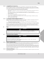
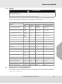
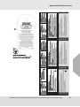
LINE CONSTRUCTION
Product Name Material Line Size Length
Aptura LT30 Nylon Web 1 1/4”x 0.07” (32mm x 2mm) 13ft-30ft
(3.9m-10m)
Workman PFL Nylon Web 3/4”x 0.10” (19mm x 3mm) 6ft-12ft
(1.8m-3.7m)
Galvanized Cable 3/16” (5mm) dia. 7ft-12ft
(2.1m-3.7m)
Workman Twin Leg PFL Nylon Web 1” x 0.088” (25mm x 2.24mm) 6ft (1.8m)
20ft Dyna-Lock Nylon Web 1”x 0.08” (25mm x 2mm) 20ft (6.1m)
Stainless Steel or
Galvanized Cable
3/16” (5mm) dia. 20ft (6.1m)
Backpacker Nylon Web 1”x 0.08” (25mm x 2mm) 20ft (6.1m)
30ft and Longer
Dyna-Lock
Stainless Steel or
Galvanized Cable
3/16” (5mm) dia. 30ft (10m)
50ft (16m)
70ft (22m)
95ft (30m)
30ft and Longer Workman Stainless Steel or
Galvanized Cable
3/16” (5mm) dia. 30ft (10m)
50ft (16m)
Lynx Rescuer Stainless Steel Cable 3/16” (5mm) dia. 50ft (16m)
95ft (30m)
Dynevac II Stainless Steel Cable 3/16” (5mm) dia. 50ft (16m)
95ft (30m)
Sure-Lock Polyester Web 1 3/4”x 0.05” (44mm x 1mm) 7ft (2.1m)
Short-Stop Polyester Web 1 3/4”x 0.05” (44mm x 1mm) 6ft (1.8m)
10ft (3.0m)

Self-Retracting Lanyard
9
Use
US
2.3.2 Compatibility of Connectors
Connectors, such as D-Rings, snaphooks, and carabiners, must be rated at 5,000 lbs (22 kN)
minimum breaking strength. Connecting hardware must be compatible in size, shape, and strength.
Non-compatible connectors may accidentally disengage. Always verify compatibility of the connecting
snaphook or carabiner with harness D-ring or anchorage connector.
- Use only self-closing, self-locking snaphooks and carabiners.
Do not attach snaphook to a D-ring or anchorage with an inside diameter smaller than 2 3/16 in.
(56 mm).
Do not use snaphooks or connectors that will not completely close when attached.
Do not attach a connector with a gate opening larger than 1.5 in. (38 mm) to the back D-ring of a
full body harness.
- Do not tie knots in a lanyard.
- Do not connect snaphooks and carabiners to each other.
- Connect ONLY snaphooks and carabiners with a minimum gate strength of 3600 lbs (16 kN)
directly to a horizontal lifeline.
- Do not hook the SRL to itself.
- Do not connect two (2) snaphooks to one (1) D-ring.
2.3.3 Anchorages and Anchorage Connectors
Personal fall arrest system anchorages and connectors must be capable of supporting a static load,
applied in each direction permitted by the system, of at least:
- Two (2) times the maximum arrest force permitted on the system when certification exists
- 5,000 lbs (22.2 kN) when uncertified
When more than one personal fall arrest system is attached to an anchorage, the anchorage strengths
set forth in (a) and (b) above shall be multiplied by the number of personal fall arrest systems attached.
Properly installed MSA horizontal lifeline systems may also be used as an anchorage for all Self-
Retracting Lanyards. Emergency Rescue SRLs may not be used in rescue mode when anchored to a
horizontal lifeline. See lifeline instructions for proper installation.
3 Use
3.1 Planning the Use of Systems
3.1.1 Rescue and Evacuation
The user must have a rescue plan and the means at hand to implement it. The plan must take into
account equipment and special training necessary to effect prompt rescue under all foreseeable condi-
tions. For confined space rescue, see OSHA regulation 1910.146 and ANSI Z117.1.
When using a Rescue SRL as part of the rescue system: anchor it in a vertical position; assure there
is enough clearance to operate the hand crank and to hold the stabilizing handle; and assure there is
enough room and fall protection for the rescuer who would operate the system. The Rescue SRL may
be used in positions other than vertical if it is attached to a system specifically designed for this appli-
cation (e.g. a tripod or davit system).
3.1.2 Fall Arrest Distance
The maximum arrest distance stated on the SRL is the total maximum distance required to arrest a fall
when used vertically.
WARNING
Do not use an SRL that was subjected to a fall arrest. SRLs that have been subjected to fall arrest
or impact forces must immediately be removed from service and tagged "UNUSABLE.".
Do not use an SRL that was subjected to abuse, such as being dropped from more than 15 ft.
Misuse can result in serious injury or death.
WARNING
Never alter an MSA Self-Retracting Lanyard.
Use only for the fall arrest of one person.
Do not use to arrest falls due to the collapse of sliding masses, e.g. grain, sand, and liquids.
Do not use a rescue SRL as a materials hoist.
Misuse can result in serious injury or death.

US
Use
Self-Retracting Lanyard
10
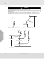
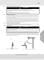
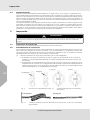
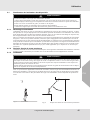
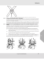
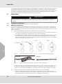
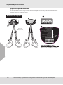
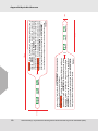
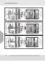
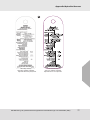
3.1.3 Set Up
Set up the SRL directly above the user for vertical fall arrest applications. A qualified person must
review and approve applications horizontally or inclined and as a restraint. Do not use the SRL as a
positioning device.
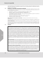
Fig. 3 Fall clearance
WARNING
Anchor the device to prevent swing falls and impact with objects in or adjacent to the fall path. Swing
falls can increase the fall distance. Serious injury or death may result.
Do Not use where objects may fall or otherwise interfere with the operation or ability of this device to
function properly.
Fig. 1 Best
Fig. 2 Potential swing falls
Fall Clearance
Max Arrest Distance
Free Fall
39” (1m) Safety Allowance

Self-Retracting Lanyard
11
Use
US
3.1.4 Fall Clearance
Always remove obstructions below the work area to ensure a clear fall path. The minimum recom-
mended clearance is the maximum arrest distance specified on the SRL's labeling plus an extra 39 in.
(1 m) and any additional free fall up to the limit stated in the specification section of this manual and
marked on the product label (see Fig. 3 Fall clearance).
When a Workman PFL, Short-Stop, or Sure-Lock is connected to the back D-ring of a harness, 2 ft of
free fall must be included in the clearance calculation and applied to the free fall limit to account for
SRL rotation during a fall arrest. See section 3.2.5 for a Twin Leg PFL.
3.1.5 Tag Line
Do not leave an SRL's line extended when it's not being used for fall protection. If the SRL is to high
to reach the retracted snaphook, then attach a sufficiently long tag line (light rope) to the snaphook.
Use the tag line to retrieve the snaphook for use and to control retraction after use.
3.2 Making Connections
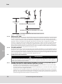
3.2.1 Anchorage Mounted SRL (not applicable to the Workman Twin Leg PFL)
- Connect the SRL's anchorage bracket to a suitable anchorage with the appropriate connecting
hardware.
- Connect the snaphook to the back D-ring (or CSA Class A connector) of an approved full body
harness.
- Be sure the snaphook's gate is completely closed and locked. Verify a rescue SRL is set to fall
arrest mode before connecting it to an anchorage (see instructions on rescue SRL).
Fig. 4 Fall arrest attachment D-ring (or class A connector)
3.2.2 User Mounted SRL
The anchorage bracket of SRLs 12 ft (3.7 m) or shorter, may be connected to the back D-ring (or CSA
Class A connector) of an approved full body harness. The nozzle of the Backpacker SRL may also be
connected to the back D-ring of an approved full body harness.
In these applications, the snaphook is connected to a suitable anchorage with the appropriate
connecting hardware. If the SRL remains attached to the harness when it's not being used, then secure
the snaphook end of the line to prevent it from becoming a trip hazard.
3.2.3 Backpacker Mount (Backpacker SRL only)
The Backpacker SRL may be connected to the back D-ring of a user's harness by utilizing the connec-
tion element on the nozzle. When using the connection element on the nozzle, the snaphook is
connected to a suitable anchorage and the Backpacker's nozzle is connected to a 2 3/16 in. (56 mm)
back D-ring of an approved full body harness.
Follow the procedure below to connect the Backpacker using its nozzle connection element:
(1) Insert the snaphook and nozzle of the Backpacker through the D-ring of the harness in the direc-
tion that will have the nozzle of the Backpacker pointing upward when the harness is on the user.
(2) Press the D-ring of the harness against the spring loaded arms of the nozzle until the D-ring
snaps into the groove under the arms of the nozzle.
(3) Put the harness on the user in accordance with the directions supplied with the harness.
WARNING
Do not rely on feel or sound to verify proper snaphook engagement. Always check visually for proper
engagement. Ensure that gate and keeper are closed before use.

US
Use
Self-Retracting Lanyard
12
(4) Connect the snaphook to a suitable anchorage connector. If the anchorage connector is out of
reach, then use MSA's Remote Connect/Disconnect System.
The Backpacker can be removed by first taking the harness off the user, pressing the spring loaded
arms on the nozzle, and sliding the D-ring past the arms.
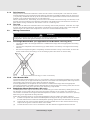
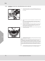
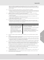
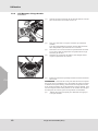
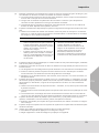
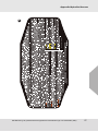
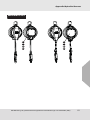
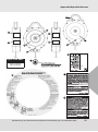
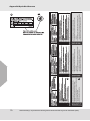
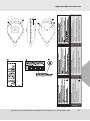
3.2.4 Workman Twin Leg PFL
Installation
Fig. 5 Insert Fig. 6 Connect Fig. 7 Disconnect
(1) Insert the back D-ring of the harness into the D-ring
connector located on the PFL.
(2) Ensure the D-ring is correctly installed by pulling back on
the D-ring.
Both tabs of the PFL should be closed preventing the
D-ring from exiting the unit.
(3) Orient the PFL on the harness with the D-ring at the
bottom of the unit and the lanyard legs exiting the top of
the unit.
(4) Connect the securing straps to the upper torso straps of
the harness.

Self-Retracting Lanyard
13
Use
US
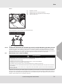
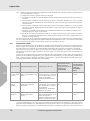
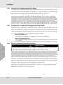
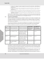
Removal
Never connect another user to the second line.
Fig. 8 Incorrect attachment
3.2.5 Workman Twin Leg PFL Alternate Installation
The Workman Twin Leg PFL can also be installed without the use of securing straps. However, to
account for PFL rotation during a fall arrest, additional free fall of 2 ft must be included in the fall clear-
ance calculation and applied to the free fall limit.
(5) Don the harness as outlined by the instructions supplied
with it.
NOTE: If the harness does not have lanyard keepers (to
secure the PFL's lanyard leg(s) when not used), then install the
keepers included with each Workman Twin Leg PFL. These
keepers are to be placed on the front harness torso straps near
the worker's chest.
(6) Use the keepers to secure the lanyard leg not in use.
(1) Take off the harness.
(2) Undo the securing straps.
(3) Press both tabs together simultaneously.
(4) Pull on the D-ring.
N!
Incorrect Attachment

US
Use
Self-Retracting Lanyard
14
3.3 Moving around the Work Area
Move around carefully to prevent loss of balance from line tension or locking. Move toward the
anchorage at a rate that will not allow line slack. Move away from the anchorage at a rate that is less
than the device locking velocity. Avoid quick or sudden movement in any direction.
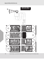
3.3.1 Workman Twin Leg PFL Usage
The Workman Twin Leg PFL is intended to give users 100% tie-off when moving around the work site.
One of the legs must be attached to an appropriate anchorage connector while the user moves to the
new location. At the new location, attach the second leg to an appropriate anchorage connector before
disconnecting the original leg. Repeat this process until the final destination has been reached.
3.4 Rescue SRLs (Lynx and Dynevac II)
Rescue SRLs may be used as a rescue device for a user that has experienced a fall. Rescue SRLs
are used as a standard SRL for fall protection until switched to rescue mode. The capacity of a Rescue
SRL in fall arrest and rescue modes is one person. See the Rescue SRL's labels for the specific weight
capacity.
The instructions in this manual for a standard SRL apply to the Rescue SRL when in the fall arrest
mode. This section of the instructions explains the use in rescue mode. A Rescue SRL in rescue mode
can not be used for fall protection.
3.4.1 Setting the Rescue SRL to Rescue Mode
The rescue personnel must be equipped with the proper fall protection when applicable. If the indi-
vidual being rescued is not connected to the Rescue SRL, then pay out line while the Rescue SRL is
in fall arrest mode and connect the snaphook to the back D-ring (or CSA Class A connector) on the
harness of the individual being rescued. Once the individual is connected to the Rescue SRL, then the
Rescue SRL can be set to rescue mode.
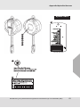
Carefully follow the directions below to set the Rescue SRL into rescue mode:
(1) Remove pins #1 (side) then #2 (top).
For the Lynx Rescuer:
Pull the activation knob on the red hub at the center of the handle.
The lock will pop out.
For the Dynevac II:
Pull the ball lock pin from the hub at the center of the handle by depressing the pin button.
(2) Rotate the handle clockwise at least 1/2 turn in order to engage the mechanism.
3.4.2 Raising and Lowering during Rescue
Raise or lower the individual being rescued by turning the crank in the appropriate direction as indi-
cated on the Rescue SRL. Do not allow slack in the line during rescue. If slack develops, then the indi-
vidual being rescued could fall a second time. Auto braking will lock the unit when the handle is
released. See the labels on the Rescue SRL for the maximum force required to rotate the handle when
the rescuer is loaded to capacity.
Use extreme care when the individual being rescued reaches a safe location and is being disconnected
from the rescue system. With the individual being rescued at a safe level, the rescuer(s) must move
the individual laterally, and then lower the individual onto to a safe and stable surface where medical
assistance can be administered or the individual can be transported.
Caution must be used during this move so that the rescuer(s) does not fall. If a portable anchorage is
WARNING
Keep line clear of other workers, objects, and obstructions.
Do not clamp off, knot, or stand on line.
Do not permit line slack.
Do not allow the line to pass around the body or limbs.
Do not lengthen line by connecting to another line.
Do not release the line and allow it to freely retract back into the housing.
DO NOT allow lines of a Workman Twin Leg PFL to become entangled or twisted.
Never connect another user to the second line of a Workman Twin Leg PFL.
WARNING
Always maintain tension on line when using in Rescuer Mode. Do not allow slack line. Pull on line if
necessary. Failure to do so can result in serious injury or death.

Self-Retracting Lanyard
15
Care, Maintenance and Storage
US
being used to support the Rescue SRL (e.g. a tripod), then use great care to avoid toppling the
anchorage while moving the individual to the safety location.
3.4.3 Resetting the Rescue SRL to Fall Arrest Mode
Carefully follow the directions below to reset the Rescue SRL into fall arrest mode:
(1) Remove any load attached to the line and crank any remaining line back into the unit.
Always keep tension on the line for proper retraction.
For the Lynx Rescuer:
Pull out the activation knob on the red hub and rotate it 90° so that it remains out.
Insert key in lock and rotate clockwise 1/4 turn, depress the lock, release activation knob by
rotating it. The lock should now be secured in the depressed position.
Turn the key counterclockwise and remove it from the lock.
For the Dynevac II:
Depress the red reset button into the handle hub.
Align the hole in the reset pin with the matching hole in the hub.
Insert the ball lock pin through the handle hub while depressing the pin's end button.
(2) Rotate the crank handle to the upright storage position and insert pins #2 (top) then #1 (side).
(3) Verify the Rescue SRL is in fall arrest mode by paying out line and observing that it automatically
retracts back into the unit.
Always leave the Rescue SRL in fall arrest mode.
4 Care, Maintenance and Storage
4.1 Cleaning
Strictly adhere to the cleaning instructions in this section to prevent adverse effects on the materials
used in the SRL. Clean the SRL periodically with a clean damp (not wet) cloth to remove dirt or contam-
ination which may cause corrosion, hamper operation, or diminish readability of the labels.
To remove oil or grease, use a mild laundry detergent. Do not use chemicals, harsh detergents, abra-
sives, or pressure washers. Never immerse the SRL in water or other liquid. Excessive accumulation
of dirt, paint or other foreign matter may prevent proper function of the SRL, and, in severe cases,
weaken the line.
Contact MSA with questions concerning product conditions and cleaning. Some environments may
require the SRL be disinfected. Contact MSA for aid in determining the proper disinfection procedure
for the specific application.
4.2 Maintenance and Repairs
Tag damaged equipment or equipment needing maintenance as "UNUSABLE" and remove from
service. Repair and maintenance (other than cleaning) must be performed by an MSA authorized
service center. Moving parts of snaphooks and carabiners may require periodic lubrication with low
viscosity penetrating oil. Follow lubricant manufacturer's instructions. Do not over-lubricate. Wipe
excess with a clean, dry cloth.
Canadian standard CSA Z259.2.2-17 requires that the manufacturer, or manufacturer approved agent,
inspect and perform maintenance on all SRLs and SRL-Rs two (2) years after date of manufacture and
annually thereafter.
4.3 Transportation
Protect the line at the nozzle during transportation to prevent damage. Secure the SRL housing and
snaphook from movement when possible.
4.4 Storage
Store the SRL in a cool, dry and clean place out of direct sunlight. Avoid areas where heat, moisture,
light, oil, and chemicals or their vapors or other degrading elements may be present. Never allow SRL
to rest for lengthy periods of time on concrete or ash floors as lime sulfur and ash can cause corrosion.
Store the SRL with line fully retracted.
Equipment which is damaged or in need of maintenance should not be stored in the same area as
usable equipment. Heavily soiled, wet, or otherwise contaminated equipment should be properly main-
tained (e.g. dried and cleaned) prior to storage. Prior to using equipment which has been stored for
long periods of time, a formal inspection should be performed by a competent person.

US
Inspection
Self-Retracting Lanyard
16
5 Inspection
5.1 Inspection Frequency
Inspect the SRL before each use.
5.2 Inspection Procedure
Perform the following steps in order. If in doubt about any inspection point, consult MSA or a competent
person qualified to perform formal inspection. Immediately remove from service any device that does
not comply with the requirements of any step below.
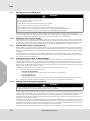
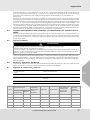
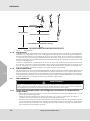
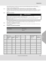
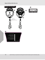
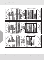
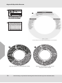
(1) Inspect load indicator to verify it is not deployed.
The load indicator is located either on the snaphook, at the anchorage connector, or on the
line (Workman Twin Leg PFL, Sure-Lock, Short-Stop).
Load indicators deploy by shearing a pin or tearing stitching at folds in the web (Workman
Twin Leg PFL, Sure-Lock, Short-Stop). Figures below depict deployed vs. not deployed indi-
cators of each type.
(2) Inspect labels to verify that they are present and legible.
Check the competent person inspection grid to be sure a competent person has performed
an inspection within six (6) months (3 months for severe conditions) as outlined in section 5.3.
Formal Inspection.
(3) Inspect line extraction and retraction by pulling out the full length of line and letting it retract back
into the housing in a controlled manner.
The line operation must be smooth without jerking during extraction or stalling during retrac-
tion.
The line must retract completely into the housing. Confirm device locks by quickly pulling line
out of the housing.
The device must lock and remain locked until line tension is relaxed. Repeat three times.
WARNING
Inspect the SRL as instructed on the labels and in this manual. Failure to follow the instructions can
result in serious injury or death.
Fig. 9 Snaphooks (typical)
Fig. 10 SRLs (typical)
Fig. 11 Workman Twin Leg PFL, Sure-Lock, Short-Stop (typical)
Some SRLs may have two load indicators. Remove an SRL from service if one or more load
indicators have deployed. Not all SRLs will have a load indicator.
Not Deployed
Deployed
Deployed
Not Deployed
Not Deployed Deployed

Self-Retracting Lanyard
17
Inspection
US
(4) Inspect for structural damage and corrosion.
Verify that the housing attachments are tight; that there are no missing or altered parts; that
there are no cracks, deformations, or deep cuts in the housing, line, or snaphook.
(5) Inspect all metallic parts for evidence of damage, alteration and missing parts.
(6) Inspect the D-ring connector on the Workman Twin Leg PFL for proper operation.
The locking tabs should pivot freely and spring back into the locked position.
Insert and remove a back D-ring of a harness several times to confirm the tabs lock and
unlock correctly.
Look for deformation, fractures, corrosion, excessive wear, and loose parts.
(7) Inspect snaphooks for deformation, fractures, cracks, corrosion, deep pitting, burrs, sharp
edges, cuts, deep nicks, loose parts, and evidence of excessive heat or chemical exposure.
Check function: unlock, open, close, and lock several times.
The Gate must automatically close and snugly seat against nose.
The locking mechanism must retain the gate tip within 1/8 in. (3 mm) of the nose when firm
pressure is applied to the gate.
(8) Inspect all plastic parts for cuts, breaks, alteration, excessive wear, missing and loose parts.
Inspect for evidence of burns, excessive heat or chemical attack.
(9) Inspect each component and subsystem of the complete system in accordance with the associ-
ated manufacturer's instructions.
(10) Verify Rescue SRLs operate properly in rescue mode.
Secure the unit and apply a load to the line.
Set the unit to rescue mode as outlined in the instructions on the unit.
Line should pay out when the handle is rotated in the "LOWER" direction as specified on the
unit. Always keep tension on line for proper pay out.
Line should retract when the handle is rotated in the "RAISE" direction as specified on the
unit. Always keep tension on line for proper retraction.
Return the unit to fall arrest mode as outlined in the instructions on the unit.
Verify all pins are in place on the crank handle and that the key lock on the Lynx and reset
button on the Dynevac II are depressed and locked in position.
If, after inspecting the SRL, there is any doubt about its condition for safe use, then it is essential for
safety that the SRL be immediately removed from service and not used again until confirmed in writing
by a competent person that it is acceptable to do so.
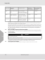
5.3 Formal Inspection
MSA recommends periodic factory authorized recertification of mechanical devices according to the
intervals in the table below. While this is considered best practice, it is ultimately at the discretion of
the competent person. MSA requires periodic competent person inspection by someone other than the
user according to the intervals in the table below or local regulations. This is not optional.
A competent person is an individual designated by an employer who is responsible for the employer’s
fall protection program, and through training and knowledge, is capable of identifying, evaluating, and
addressing existing and potential hazards and who has the authority to take action (see ANSI Z359.0
for further detail).
For devices with cable lines: For devices with web lines:
- Inspect the ferrules or splice and
thimble at the snaphook and verify
there is no evidence of cracks,
distortion, corrosion, wear, or biting
into the line.
- Inspect the entire length of line and
verify there are no kinks, bends, bird
caging, changes in diameter, corro-
sion, or broken wires.
- Inspect the web and verify that it has no
broken, frayed, cut, abraded, or missing
threads.
- Verify there are no reductions in width or
thickness of the web.
- Verify there are no smooth, discolored, shiny,
hardened, or glazed areas that indicate expo-
sure to heat or chemicals.

US
Inspection
Self-Retracting Lanyard
18
CSA Z259.2.2-17 requires SRLs and SRL-Rs be sent to a factory authorized entity for inspection and
maintenance no more than 2 years after the date of manufacture and annually thereafter. See SRL
labels to determine whether it’s a CSA SRL or SRL-R.
Record formal inspections in the provided Inspection Log. Punch or indelibly mark the Inspection grid
attached to the SRL. Do not use an SRL with a formal inspection date older than twelve (12) months.
Tag SRLs with formal inspections that are out of date as “UNUSABLE” and remove from service until
after formal inspection. The safety of users depends upon the continued efficiency and durability of the
SRL. MSA recommends keeping a log of formal inspections for all components in a fall protection
system or subsystem.
5.4 SRLs with Radio Frequency Identification (RFID)
Some SRLs include an RFID chip that can be accessed by an RFID scanner to help track inspection
and service information. RFID chip locations for applicable products are shown in the figures of section
2.2 in this manual.
5.5 Corrective Action
SRLs that do not meet the inspection criteria must be tagged "UNUSABLE" and removed from service
immediately. Some SRLs may be repairable. Contact MSA for further information.
5.6 Factory Service and Repair
Contact MSA service at 1-800-672-2222 to arrange for inspection and service of an SRL.
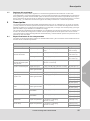
Type of Use
Application
Examples
Conditions of Use
REQUIRED
Competent
Person Inspec-
tion Frequency
RECOMMENDED
Factory Authorized
Recertification
Frequency
Infrequent to
Light
Rescue & confined
space, Factory mainte-
nance
Good storage conditions,
indoor or infrequent
outdoor use, room temper-
ature, clean environments
Annually At least every
2-5 years
Moderate to
Heavy
Transportation, Resi-
dential construction,
Utilities, Warehouse
Fair storage conditions,
indoor and extended
outdoor use, all tempera-
tures, clean or dusty envi-
ronments
Semi-annually to
annually
At least every
1-2 years
Severe to
Continuous
Commercial construc-
tion, Oil & Gas, Mining
Harsh storage conditions,
prolonged or continuous
outdoor use, all tempera-
tures, dirty environment
Quarterly to semi-
annually
At least annually
WARNING
Remove unit from service if the load indicator is deployed.
Never attempt field repairs.
Only MSA or parties with written authorization from MSA may repair an MSA self retracting lanyard.
Misuse can result in serious injury or death.

Self-Retracting Lanyard
19
Inspection
US
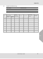
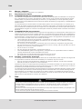
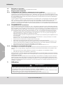
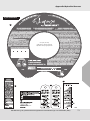
5.7 Inspection and Service Log
Product Name.: Manufacture Date:
Model No.: Purchase Date:
Serial No.: Date Put Into Service:
Product Type:
Date
Inspection or
Service Type
Factory
Authorized
Serviceman
Inspector Disposition
Comments/
Service Report
Number
Next Inspec-
tion Date
Competent
Person
Factory
Page is loading ...
Page is loading ...
Page is loading ...
Page is loading ...
Page is loading ...
Page is loading ...
Page is loading ...
Page is loading ...
Page is loading ...
Page is loading ...
Page is loading ...
Page is loading ...
Page is loading ...
Page is loading ...
Page is loading ...
Page is loading ...
Page is loading ...
Page is loading ...
Page is loading ...
Page is loading ...
Page is loading ...
Page is loading ...
Page is loading ...
Page is loading ...
Page is loading ...
Page is loading ...
Page is loading ...
Page is loading ...
Page is loading ...
Page is loading ...
Page is loading ...
Page is loading ...
Page is loading ...
Page is loading ...
Page is loading ...
Page is loading ...

Appendix/Apéndice/Annexe
Self-Retracting Lanyard/Cuerda amortiguadora autorretráctil/Longe auto-rétractable (SRL)
56
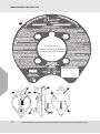
Appendix/Apéndice/Annexe
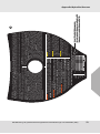
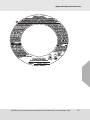
The following labels must be present, legible and securely attached./ Las siguientes etiquetas deben estar
presentes, en buen estado de legibilidad y correctamente puestas./ Les étiquettes suivantes doivent être
présentes, lisibles et solidement fixées.
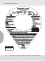
Workman Twin Leg PFLs
1.
2.
3.
RFID Location
Ubicación de RFID
Emplacement de la puce RF
1.
Model/Modelo/Modèle
Serial Number/Número de serie/Numéro de série
Date Made/Fecha de fabricación/
Date de fabrication
Meets Standards
Cumple las normas
Satisfait aux normes
Length/Longitud/Longueur
0412 Rev.3 10124848
®
Workman Twin Leg
Personal Fall Limiter
Expiration Date / Fecha de vencimiento /
Date de péremption
N/A
Made In / Fabricado en / Fait en/au/aux
China
YR
st
1
nd
2
rd
3
th
4
th
5
GRILLE D'INSPECTION EFFECTUÉE PAR UNE PERSONNE COMPÉTENTE
CUADRÍCULA DE INSPECCIÓN DE PERSONA COMPETENTE
COMPETENT PERSON INSPECTION GRID
JFMAMJJASOND
MARK GRID ON MONTH OF FIRST USE
®
Z259.2.2
2.
Page is loading ...
Page is loading ...
Page is loading ...
Page is loading ...
Page is loading ...
Page is loading ...
Page is loading ...
Page is loading ...
Page is loading ...
Page is loading ...
Page is loading ...
Page is loading ...
Page is loading ...
Page is loading ...
Page is loading ...
Page is loading ...
Page is loading ...
Page is loading ...
Page is loading ...
Page is loading ...
Page is loading ...
Page is loading ...
-
 1
1
-
 2
2
-
 3
3
-
 4
4
-
 5
5
-
 6
6
-
 7
7
-
 8
8
-
 9
9
-
 10
10
-
 11
11
-
 12
12
-
 13
13
-
 14
14
-
 15
15
-
 16
16
-
 17
17
-
 18
18
-
 19
19
-
 20
20
-
 21
21
-
 22
22
-
 23
23
-
 24
24
-
 25
25
-
 26
26
-
 27
27
-
 28
28
-
 29
29
-
 30
30
-
 31
31
-
 32
32
-
 33
33
-
 34
34
-
 35
35
-
 36
36
-
 37
37
-
 38
38
-
 39
39
-
 40
40
-
 41
41
-
 42
42
-
 43
43
-
 44
44
-
 45
45
-
 46
46
-
 47
47
-
 48
48
-
 49
49
-
 50
50
-
 51
51
-
 52
52
-
 53
53
-
 54
54
-
 55
55
-
 56
56
-
 57
57
-
 58
58
-
 59
59
-
 60
60
-
 61
61
-
 62
62
-
 63
63
-
 64
64
-
 65
65
-
 66
66
-
 67
67
-
 68
68
-
 69
69
-
 70
70
-
 71
71
-
 72
72
-
 73
73
-
 74
74
-
 75
75
-
 76
76
-
 77
77
-
 78
78


Workman Personal Fall Limiters Owner's manual
- Type
- Owner's manual
- This manual is also suitable for
Ask a question and I''ll find the answer in the document
Finding information in a document is now easier with AI
in other languages
Related papers


Other documents
-
 Aptura LT 30 Self-Retracting Lanyard Owner's manual
-
 BeamGrip FP Stryder™ Beam Anchor Owner's manual
-
3M Fall Protection Peri Operating instructions
-
3M 1410E HARNESS 1EA/CASE Operating instructions
-
 Suretyman Rescue Components Owner's manual
-
-
 V-Series V-FLEX™ Safety Harness Owner's manual
-
MSA V-EDGE Personal Fall Limiter (PFL) Operating instructions
-
Werner R210060 Owner's manual
-


