Page is loading ...

Installation Instructions
In- wall Lavatory Kit
Models 1-532T
2001 CARNEGIE AVE, SANTA ANA CA 92705
(949) 417-5207
WWW.NEWPORTBRASS.COM
05/02/2013NWP-1-532T
We Recommend Installation by a Professional Plumbing Contractor
Note: Use plumbers tape or equivalent to seal all threaded port joints.
Warning: To prevent severe damage to valve body, any solder/braze process must be per-
formed a min. of 4" from ports.
Important: : REMOVE CARTRIDGE FROM VALVE BODY(1) PRIOR TO APPLY-
ING ANY HEAT/FLAME.
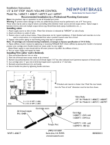
1. Secure valve BODY (1) to cross BRACE (2) using suitable SCREW (3), not included.
2. Check the horizontal and vertical level of valve BODY (1) by placing bubble level on STEMS
(4, 5). Make any necessary adjustments.
3. Utilizing a 1/2"copper supply pipe and 1/2" Socket End x 1/2"NPT Male Pipe Adapter to
sweat water supply line to inlets of Valve BODY(1), (blue STEM (4) is cold, red STEM (5) is
hot). If sweating supplies are directly connected to valve inlets, remove cartridges during this
process.
Note : If cartridges are removed during installation, re-torque to factory specification
of 14-16 ft-lbs.
4. Adjust stiffness of stem rotation by tightening or loosening TORQUE NUT. Check stiffness
by placing lever handle in horizontal position onto cartidge stem. Handle should not rotate
under its own weight.
(Note: Water supply to valve should still be off; water pressure may affect the stiffness of
stem.)
5. With STEM (4,5) in closed position, turn on water supply, pressurize system and check for
leaks.
NOTE: The following step may only be performed after finished wall surface has been com-
pleted.
6a. 1/2 NPT Spout configuration - Installer shall use appropriately sized 1/2 NPT nipple
(not included) to attach spout to valve body. Thread sealant shall be appplied to both ends of
nipple and be tightened into valve body. Tighten spout (and base ring if supplied) to nipple end
protruding from finish wall.

NWP-1-532T
REV A
6b.3/8 NPSM Spout configuration - Instller shall use the appropriate 3/8 NPSM reducer
nipple, (not supplied). Apply thread sealant to 1/2" NPT end of reducer nipple and install onto
valve BODY (1). Rough fit spout (and base ring if supplied) to reducer nipple. Tighten to
desired rotational position. Measure the excess nipple length between spout base/ring and fin-
ished wall. Remove spout and trim excess nipple length.
Trimmed end of nipple to be flat and free of sharp edges and burrs. Apply thread sealant to
trimmed nipple and re-instll spout trim.
7. Install handle escutcheon/bonnet trim and mark the cartridge all-thread nipple where
excess needs to be trimmed.
8. Remove handle escutcheon/bonnet trim and cut cartridge all-thread nipple 1/16" less than
indicated mark to prevent exposure of nipple threads.
9. Cut cartridge stem at least 1/2" to 1 5/8" past the end of the cut all-thread nipple. Final
stem length may vary based on indivitual handle base configuration.(Stem is grooved at 1/2"
intervals.)
10. Install escutcheon/bonnet trim and handle.
11. Secure handle into place by tightening handle setscrew. Note:To achieve desired handle
rotational allignment, the cartridge MUST be tightened in clockwise rotation only. DO NOT
loosen the cartridge. Factory torque of 14 ft-lbs, minimum must be maintained.
Finished Wall Dimension
Handle
Bonnet
Finished Wall
3” MIN
4” MAX
Escutcheon
Vertical
Stud Face
Cartridge Bonnet
5/8” Hex
5
1
4
3
All Thread
STEM
1/2”COPPER SWEAT (5/8” DIA)
Cold
Inlet
1/2” NPT
Hot
Inlet
Outlet Nipple 5b
(Not included)
For 3/8 NPSM spout
configurations
Outlet Nipple 5a
(Not included)
For 1/2 NPSM spout
configurations
2
05/02/2013
Torque Nut
EN-2521
Screw
/


