Legrand AMS-4424P Quick Installation guide
- Category
- Network switches
- Type
- Installation guide
This manual is also suitable for
Fo ld Fo ld Fo ld
READ ME FIRST
QUICK INSTALL GUIDE
26-Port Gigabit Stackable PoE+
L2/L3 Managed Switch
AMS-4424P
Includes:
AMS-4424P 26-Port/24-port PoE+ Switch
Power Cord
Mounting Hardware
INSTALLATION AND SETUP
1
Physical Installation
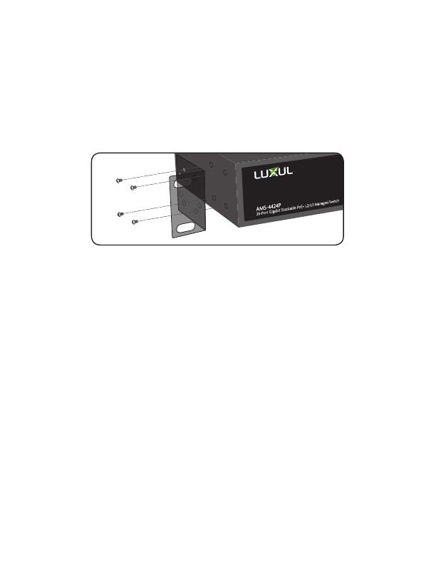
The AMS-4424P can easily be installed in a standard 19” rack. Two mounting ears
are included for installing and stabilizing the switch. When attaching the mounting
ears and installing the switch in a rack, please refer to the following illustration:
Rack-Mounting the AMS-4424P
Use the included screws to attach the mounting ears to each side
of the switch.
Mount the switch in the rack with the LEDs facing outwards. Be sure the
switch is level and properly secured in the rack.
Desktop Setup
For use as a desktop device, position and apply the included rubber feet to the
bottom of the AMS-4424P.
2
Connecting Ethernet and Power
Ethernet and Power Connections
Use one of the 26 Ethernet ports to connect the AMS-4424P to any Ethernet-
enabled device, including servers, routers or other switches.
No crossover cable is necessary.
The AMS-4424P supports 10/100/1000 Mbps Ethernet; 10/100 Mbps half/
full-duplex mode and 1000 Mbps full-duplex mode. Ports 1-48 are PoE+ and
are enabled by default. Ports 49 and 50 are Gigabit Ethernet only (non PoE).
Use the included power cable to connect the AMS-4424P to a surge-
protected outlet. The AC input socket is on the rear panel. The built-in
power supply supports 100~240VAC at 50/60Hz.
Network Cabling
Luxul recommends Category-5, super Category-5 or Category-6 unshielded
twisted pair (CAT5/CAT5e/CAT6 UTP). To ensure best performance and
stable data transmission at 1000 Mbps, use Category-6 shielded twisted pair.
c CAUTION: Multiple Uplink channels can create loops, resulting in
network failure. Ensure only one Uplink channel exists
between switches or between the AMS-4424P and a router.
n NOTE: When powering up, the port LEDs may take a moment to
initialize. This is normal as the AMS-4424P initialization and
startup sequence completes.
n NOTE: The AMS-4424P has an internal 740W power supply. Do not
exceed 25.5W each or 740W combined consumption of all
external PoE devices.
Sales
P: 801-822-5450
Technical Support
P: 801-822-5450 Option 3
LUX-QIG-AMS-4424P-v2 01251709
Copyright and Trademark Notices
No part of this document may be modified or adapted in any way, for any purposes without permission
in writing from Luxul. The material in this document is subject to change without notice. Luxul reserves
the right to make changes to any product to improve reliability, function, or design. No license is granted,
either expressly or by implication or otherwise under any Luxul intellectual property rights. An implied
license only exists for equipment, circuits and subsystems contained in this or any Luxul product.
© Copyright 2016 Luxul. All rights reserved. The name Luxul, the Luxul logo, the Luxul logo mark and
Simply Connected are all trademarks and or registered trademarks of Luxul Wireless, Inc. All other
trademarks and registered trademarks are property of their respective holders.
Fo ld Fo ld Fo ld
READ ME FIRST
QUICK INSTALL GUIDE
26-Port Gigabit Stackable PoE+
L2/L3 Managed Switch
AMS-4424P
Includes:
AMS-4424P 26-Port/24-port PoE+ Switch
Power Cord
Mounting Hardware
INSTALLATION AND SETUP
1
Physical Installation
The AMS-4424P can easily be installed in a standard 19” rack. Two mounting ears
are included for installing and stabilizing the switch. When attaching the mounting
ears and installing the switch in a rack, please refer to the following illustration:
Rack-Mounting the AMS-4424P
Use the included screws to attach the mounting ears to each side
of the switch.
Mount the switch in the rack with the LEDs facing outwards. Be sure the
switch is level and properly secured in the rack.
Desktop Setup
For use as a desktop device, position and apply the included rubber feet to the
bottom of the AMS-4424P.
2
Connecting Ethernet and Power
Ethernet and Power Connections
Use one of the 26 Ethernet ports to connect the AMS-4424P to any Ethernet-
enabled device, including servers, routers or other switches.
No crossover cable is necessary.
The AMS-4424P supports 10/100/1000 Mbps Ethernet; 10/100 Mbps half/
full-duplex mode and 1000 Mbps full-duplex mode. Ports 1-48 are PoE+ and
are enabled by default. Ports 49 and 50 are Gigabit Ethernet only (non PoE).
Use the included power cable to connect the AMS-4424P to a surge-
protected outlet. The AC input socket is on the rear panel. The built-in
power supply supports 100~240VAC at 50/60Hz.
Network Cabling
Luxul recommends Category-5, super Category-5 or Category-6 unshielded
twisted pair (CAT5/CAT5e/CAT6 UTP). To ensure best performance and
stable data transmission at 1000 Mbps, use Category-6 shielded twisted pair.
c CAUTION: Multiple Uplink channels can create loops, resulting in
network failure. Ensure only one Uplink channel exists
between switches or between the AMS-4424P and a router.
n NOTE: When powering up, the port LEDs may take a moment to
initialize. This is normal as the AMS-4424P initialization and
startup sequence completes.
n NOTE: The AMS-4424P has an internal 740W power supply. Do not
exceed 25.5W each or 740W combined consumption of all
external PoE devices.
Sales
P: 801-822-5450
Technical Support
P: 801-822-5450 Option 3
LUX-QIG-AMS-4424P-v2 01251709
Copyright and Trademark Notices
No part of this document may be modified or adapted in any way, for any purposes without permission
in writing from Luxul. The material in this document is subject to change without notice. Luxul reserves
the right to make changes to any product to improve reliability, function, or design. No license is granted,
either expressly or by implication or otherwise under any Luxul intellectual property rights. An implied
license only exists for equipment, circuits and subsystems contained in this or any Luxul product.
© Copyright 2016 Luxul. All rights reserved. The name Luxul, the Luxul logo, the Luxul logo mark and
Simply Connected are all trademarks and or registered trademarks of Luxul Wireless, Inc. All other
trademarks and registered trademarks are property of their respective holders.

Fold Fold Fold
3
Preparing for Access
IP Addressing
If the AMS-4424P is connected to a network with a 192.168.0.X address
scheme, and your computer shares a similar address on the same network,
you can skip to the next step, Access and Setup
.
n Note: If another device on your network shares the 192.168.0.4
address, you’ll need to temporarily reassign or remove that
device while you configure the AMS-4424P.
If your network uses an address scheme other than 192.168.0.X, you’ll need
to set a temporary static IP address on the computer you’re using for
configuration. To do so, set the IP address of your computer to an address
in the 192.168.0.X range, then set the Gateway/Router address to 192.168.0.4
(the default IP address of the AMS-4424P).
Once you’re finished configuring the switch, you can return your comput-
er’s IP configuration to normal, typically “Obtain Automatically/DHCP.”
n Note: Visit http://luxul.com/ip-addressing to learn more about
changing your computer’s IP address and getting connected.
4
Access and Setup
Getting Connected
Use an Ethernet cable to connect your computer to the AMS-4424P, then
power on the switch.
Logging In
To access the AMS-4424P web configuration, open your web browser and
enter the switch’s default 192.168.0.4 IP address in the address field. Log in to
the switch using the default user name and password:
Default IP: 192.168.0.4
Username: admin
Password: admin
Select the menu items on the left to view and/or modify the configuration.
Refer to the Quick Setup Guide at Luxul.com for more detailed information on
setup, IP configuration and routing, PoE, VLANs, Spanning Tree, and Stacking.
5
Hardware Operation
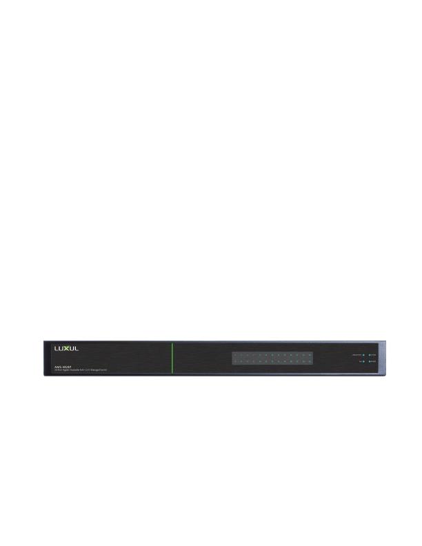
Front Panel
The front panel of the AMS-4424P Switch includes dual colored Link/Activity
LEDs that can be switched from green to blue. In addition, the front panel has
Link/Activity and PoE mode indicators as well as System and Power LEDs.
AMS-4424P Front Panel View
Rear Panel
The rear panel of the AMS-4424P Switch includes 1 console port, 24 Gigabit
RJ-45 Ports and 2 optical expansion ports that accommodate both 1 Gigabit SFP
and 10 Gigabit SFP+ modules (for stacking), as well as LED indicators for each
port. Each Gigabit port has one Link/Activity/PoE LED. A push button switch
with an LED indicator switches the display between Link/Activity and PoE.
LED Indicators
The LED indicators on the AMS-4424P include System, Link/Act and PoE LEDs,
and an LED for each port. These LED indicators show the operating status of
the AMS-4424P and each port connection.
Mode/Reset Button to Change LED Functionality
Tapping the Mode/Reset button briefly switches the port indicator between
displaying port link speed and PoE status.
The following chart shows the LED indicators of the AMS-4424P along with an
explanation of the indicator’s properties:
Indicator
Name
Description
System
Green Flashing Indicates normal operation.
Green On Indicates a malfunction. Contact support.
Red On Indicates power-on system initialization.
O Indicates startup/initialization process or
that power is not on.
Port Link/
Act Status
1-50
Green 1000Mbps device connected to the port.
Yellow 10/100Mbps device connected to the port.
Flashing Port receiving or transmitting data.
O Nothing connected to the port.
Port PoE
Status 1-50
Green Switch is providing PoE power to a device.
Yellow PoE is o due to a fault or because the
connected device is exceeding power limit.
O Port disconnected or link failed.
Note: At startup, the port LEDs will flash briefly during a self-test.
Mode/Reset Button to Reset/Restore
The Reset button (located at the lower-left corner of the front panel) is
used to reset (reboot) the switch, or to restore the switch to factory
default settings.
X
To Reboot/Reset the Switch: With the AMS-4424P powered on, press
the Reset button for approximately three seconds until the Link/Act and
PoE LEDs both light, then release the button.
c CAUTION: Do not hold the button for more than four seconds.
Doing so could erase all settings and restore
factory defaults.
X
To Restore Default Settings: With the AMS-4424P powered on, press
and hold the Reset button approximately eight seconds, until both the
Link/Act and PoE LEDs turn o, then release the Reset button and the
switch automatically restores factory default settings and reboots. Once
the System LED starts flashing again, the AMS-4424P is running with
factory defaults.
c CAUTION: Please note that restoring Default Settings will remove
any/all custom configuration.
Fold Fold Fold
3
Preparing for Access
IP Addressing
If the AMS-4424P is connected to a network with a 192.168.0.X address
scheme, and your computer shares a similar address on the same network,
you can skip to the next step, Access and Setup
.
n Note: If another device on your network shares the 192.168.0.4
address, you’ll need to temporarily reassign or remove that
device while you configure the AMS-4424P.
If your network uses an address scheme other than 192.168.0.X, you’ll need
to set a temporary static IP address on the computer you’re using for
configuration. To do so, set the IP address of your computer to an address
in the 192.168.0.X range, then set the Gateway/Router address to 192.168.0.4
(the default IP address of the AMS-4424P).
Once you’re finished configuring the switch, you can return your comput-
er’s IP configuration to normal, typically “Obtain Automatically/DHCP.”
n Note: Visit http://luxul.com/ip-addressing to learn more about
changing your computer’s IP address and getting connected.
4
Access and Setup
Getting Connected
Use an Ethernet cable to connect your computer to the AMS-4424P, then
power on the switch.
Logging In
To access the AMS-4424P web configuration, open your web browser and
enter the switch’s default 192.168.0.4 IP address in the address field. Log in to
the switch using the default user name and password:
Default IP: 192.168.0.4
Username: admin
Password: admin
Select the menu items on the left to view and/or modify the configuration.
Refer to the Quick Setup Guide at Luxul.com for more detailed information on
setup, IP configuration and routing, PoE, VLANs, Spanning Tree, and Stacking.
5
Hardware Operation
Front Panel
The front panel of the AMS-4424P Switch includes dual colored Link/Activity
LEDs that can be switched from green to blue. In addition, the front panel has
Link/Activity and PoE mode indicators as well as System and Power LEDs.
AMS-4424P Front Panel View
Rear Panel
The rear panel of the AMS-4424P Switch includes 1 console port, 24 Gigabit
RJ-45 Ports and 2 optical expansion ports that accommodate both 1 Gigabit SFP
and 10 Gigabit SFP+ modules (for stacking), as well as LED indicators for each
port. Each Gigabit port has one Link/Activity/PoE LED. A push button switch
with an LED indicator switches the display between Link/Activity and PoE.
LED Indicators
The LED indicators on the AMS-4424P include System, Link/Act and PoE LEDs,
and an LED for each port. These LED indicators show the operating status of
the AMS-4424P and each port connection.
Mode/Reset Button to Change LED Functionality
Tapping the Mode/Reset button briefly switches the port indicator between
displaying port link speed and PoE status.
The following chart shows the LED indicators of the AMS-4424P along with an
explanation of the indicator’s properties:
Indicator
Name
Description
System
Green Flashing Indicates normal operation.
Green On Indicates a malfunction. Contact support.
Red On Indicates power-on system initialization.
O Indicates startup/initialization process or
that power is not on.
Port Link/
Act Status
1-50
Green 1000Mbps device connected to the port.
Yellow 10/100Mbps device connected to the port.
Flashing Port receiving or transmitting data.
O Nothing connected to the port.
Port PoE
Status 1-50
Green Switch is providing PoE power to a device.
Yellow PoE is o due to a fault or because the
connected device is exceeding power limit.
O Port disconnected or link failed.
Note: At startup, the port LEDs will flash briefly during a self-test.
Mode/Reset Button to Reset/Restore
The Reset button (located at the lower-left corner of the front panel) is
used to reset (reboot) the switch, or to restore the switch to factory
default settings.
X
To Reboot/Reset the Switch: With the AMS-4424P powered on, press
the Reset button for approximately three seconds until the Link/Act and
PoE LEDs both light, then release the button.
c CAUTION: Do not hold the button for more than four seconds.
Doing so could erase all settings and restore
factory defaults.
X
To Restore Default Settings: With the AMS-4424P powered on, press
and hold the Reset button approximately eight seconds, until both the
Link/Act and PoE LEDs turn o, then release the Reset button and the
switch automatically restores factory default settings and reboots. Once
the System LED starts flashing again, the AMS-4424P is running with
factory defaults.
c CAUTION: Please note that restoring Default Settings will remove
any/all custom configuration.

Fo ld Fo ld Fo ld
READ ME FIRST
QUICK INSTALL GUIDE
26-Port Gigabit Stackable PoE+
L2/L3 Managed Switch
AMS-4424P
Includes:
AMS-4424P 26-Port/24-port PoE+ Switch
Power Cord
Mounting Hardware
INSTALLATION AND SETUP
1
Physical Installation
The AMS-4424P can easily be installed in a standard 19” rack. Two mounting ears
are included for installing and stabilizing the switch. When attaching the mounting
ears and installing the switch in a rack, please refer to the following illustration:
Rack-Mounting the AMS-4424P
Use the included screws to attach the mounting ears to each side
of the switch.
Mount the switch in the rack with the LEDs facing outwards. Be sure the
switch is level and properly secured in the rack.
Desktop Setup
For use as a desktop device, position and apply the included rubber feet to the
bottom of the AMS-4424P.
2
Connecting Ethernet and Power
Ethernet and Power Connections
Use one of the 26 Ethernet ports to connect the AMS-4424P to any Ethernet-
enabled device, including servers, routers or other switches.
No crossover cable is necessary.
The AMS-4424P supports 10/100/1000 Mbps Ethernet; 10/100 Mbps half/
full-duplex mode and 1000 Mbps full-duplex mode. Ports 1-48 are PoE+ and
are enabled by default. Ports 49 and 50 are Gigabit Ethernet only (non PoE).
Use the included power cable to connect the AMS-4424P to a surge-
protected outlet. The AC input socket is on the rear panel. The built-in
power supply supports 100~240VAC at 50/60Hz.
Network Cabling
Luxul recommends Category-5, super Category-5 or Category-6 unshielded
twisted pair (CAT5/CAT5e/CAT6 UTP). To ensure best performance and
stable data transmission at 1000 Mbps, use Category-6 shielded twisted pair.
c CAUTION: Multiple Uplink channels can create loops, resulting in
network failure. Ensure only one Uplink channel exists
between switches or between the AMS-4424P and a router.
n NOTE: When powering up, the port LEDs may take a moment to
initialize. This is normal as the AMS-4424P initialization and
startup sequence completes.
n NOTE: The AMS-4424P has an internal 740W power supply. Do not
exceed 25.5W each or 740W combined consumption of all
external PoE devices.
Sales
P: 801-822-5450
Technical Support
P: 801-822-5450 Option 3
LUX-QIG-AMS-4424P-v2 01251709
Copyright and Trademark Notices
No part of this document may be modified or adapted in any way, for any purposes without permission
in writing from Luxul. The material in this document is subject to change without notice. Luxul reserves
the right to make changes to any product to improve reliability, function, or design. No license is granted,
either expressly or by implication or otherwise under any Luxul intellectual property rights. An implied
license only exists for equipment, circuits and subsystems contained in this or any Luxul product.
© Copyright 2016 Luxul. All rights reserved. The name Luxul, the Luxul logo, the Luxul logo mark and
Simply Connected are all trademarks and or registered trademarks of Luxul Wireless, Inc. All other
trademarks and registered trademarks are property of their respective holders.
-
 1
1
-
 2
2
-
 3
3
-
 4
4
-
 5
5
-
 6
6
-
 7
7
-
 8
8


Legrand AMS-4424P Quick Installation guide
- Category
- Network switches
- Type
- Installation guide
- This manual is also suitable for
Ask a question and I''ll find the answer in the document
Finding information in a document is now easier with AI
Related papers
-
Legrand AMS-1816P Installation guide
-
-
Legrand RT-20 User guide
-
-
-
-
-
Legrand XPE-2500 Installation guide
-
-
Other documents
-
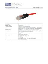 Cables Direct XXURT-615R Datasheet
-
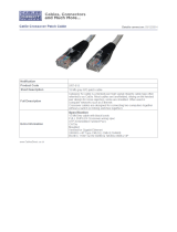 Cables Direct XRT-615 Datasheet
-
Luxul Epic 5 Quick Install Manual
-
Key Digital KD-IP1080Tx User guide
-
-
-
DigitaLinx IP 2100 Series Configuration manual
-
-
ZeeVee ZyPerMX4 User manual
-
ADTRAN SDX 8110-24-740W Quick start guide

