Page is loading ...

User’s Manual
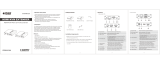
EX-HDU Series
HDMI and USB Extension on single CAT6
with Audio Out and Integrated Control System
Part Number Function
EX-HDU-WP Sender Wall Plate (Decora
®
Style)
EX-HDU-R Receiver
EX-HDU-R-IP Receiver with IP/LAN Control & Web GUI
Order toll-free in the U.S. 800-959-6439
FREE technical support, Call 714-641-6607 or fax 714-641-6698
Mail order: Hall Research, 1163 Warner Ave. Tustin, CA 92780
Web site: www.hallresearch.com E-mail: [email protected]
CUSTOMER
SUPPORT
INFORMATION
UMA1264 Rev A

EX-HD
U
2
Tabl
e
1.0 Intr
o
Features
2.0 Pac
k
3.0 Set
u
Installati
4.0 Con
n
EX-HDU
EX-HDU
5.0 Tro
u
Contacti
n
6.0 Spe
c
U
© Copyright 2018
H
e
of Cont
e
o
duction ........
.
........................
.
k
age Contents
u
p .....................
.
on ....................
.
n
ector and In
d
wall-plate Se
n
Receiver ........
.
u
bleshooting .
.
n
g Hall Resear
c
c
ifications ......
.
H
all Research, Inc.
e
nts
.
........................
.
........................
........................
.
........................
.
........................
d
icator Funct
i
n
der ..................
.
........................
.
........................
c
h ......................
.
........................
........................
.
........................
.
........................
.
........................
.
........................
.
i
ons .................
.
........................
.
........................
.
........................
.
........................
.
........................
.
.
.......................
3
.
.......................
4
.
.......................
5
.
.......................
5
.
.......................
5
.
.......................
6
.
.......................
6
.
.......................
7
.
.......................
9
.
.......................
9
.
..................... 1
0
3
4
5
5
5
6
6
7
9
9
0

Dd
HDMI and USB Extension on sin
g
le CAT6
© Copyright 2018 Hall Research, Inc.
3
1.0 Introduction
The EX-HDU is used to extend HDMI video and USB data on a single Cat6 cable
up to 200 ft (60 meters). HDMI audio is extracted and is provided both as analog
stereo and multi-channel digital. The EX-HDU can also be used to control other
equipment by providing programmable contact closure I/O, RS-232 output, IR
output, and optional LAN interface with internal WebGUI and IP control.
The EX-HDU extender consists of an EX-HDU-WP single-gang wall plate
transmitter and an EX-HDU-R (or EX-HDU-R-IP) receiver. They connect using
standard CAT5e/6 UTP cabling up to 200 feet (60 Meters) long.
The wall-plate Sender gets its power from the Receiver via the same UTP cable
and does not need a separate power supply. For convenience, the wall plate
features a USB hub with two USB ports for connection of USB devices. The plug-
and-play extender is compatible with all PCs, MACs, and Android Tablets and
does not require driver installation. Simply plug the PC's HDMI and USB ports to
the sender and make them available at the remote receiver.
The Receiver provides HDMI video output, stereo audio output, 4 USB ports, IR
output, and a terminal strip that has RS-232 output plus 4 programmable digital
I/O ports. A mini-USB port is also provided for configuration upload from a PC
for cases where the Receiver is used also as a control system.
Receiver with IP connectivity is the model EX-HDU-R-IP. It provides an
ETHERNET port for control via IP commands or internal webpage.
Users can upload RS-232 commands to the EX-HDU to control other equipment
such as turning a projector on and off. Commands can be triggered
automatically
by detecting video, or manually via the internal WebGUI, or by
sensing open and close contact events on the I/O ports.

EX-HD
U
4
For exam
232 com
m
configure
d
OUTPUT,
i
projector
A free PC
s
command
Features
• E
x
• S
u
•
W
h
o
• R
c
o
• P
e
•
W
•
R
U
© Copyright 2018
H
ple, a simple togg
l
m
ands for turning
d
to act as INPUT
S
i
t can trigger rela
y
screen.
s
oftware is availa
b
s.
T
x
tends HDMI + U
S
u
pports HDTV re
s
W
all plate sender
h
o
st PC
eceiver provides
H
o
ntrol, and conta
c
e
rfect for Interac
t
W
all plate does no
t
eceiver is availab
l
Example of Web
G
(for units with I
P
H
all Research, Inc.
l
e switch can be c
a projector on an
d
S
or OUTPUTS. W
h
y
s, for example to
b
le for configurin
g
ypical Connectio
n
S
B 2.0 to 200 ft (6
s
olutions to 1080
p
h
as 2-port hub for
H
DMI output, 4 U
S
c
t closure I/O, an
d
t
ive displays, Soft
t
require separat
e
l
e with optional I
P
G
UI control
P
interface)
onnected remote
l
d
off. The I/O por
t
h
en an I/O port is
lower or raise a
m
g
the system and
t
n
Diagram
0 m) on one Cat
6
p
60 Hz
connection to US
S
B ports, RS-232
f
d
stereo audio out
p
CODECs, and KV
M
e
power supply
P
and WebGUI co
n
l
y to activate RS-
t
s can be
configured as
m
otorized
t
o upload control
6
cable
B devices to the
f
or display
p
uts
M
extension
n
trol

Dd
HDMI and USB Extension on sin
g
le CAT6
© Copyright 2018 Hall Research, Inc.
5
2.0 Package Contents
EX-HDU-WP
(1) Decora Wallplate with (2) screws
(1) 4-Position Terminal Strip
(1) Type A to B USB Cable
EX-HDU-R and EX-HDU-R-IP
(1) 12V DC Universal DC Power Adapter
(2) 6-Position Terminal Strip
(1) Type A to Mini-B USB cable
(1) User's Manual
3.0 Setup
Installation
• Connect the sender (EX-HDU-WP) and the receiver (EX-HDU-R) with a
CAT6 cable.
• Connect the HDMI source (such as video from a PC) to the wall plate's
HDMI input.
• Optionally, connect the wall plate's USB HOST (type B) connector to a
compatible HOST computer via the supplied cable.
• Optionally, connect compatible USB devices into the wall plate's USB hub
connectors or the USB HUB connectors on the receiver.
• Optionally, connect the HDMI extracted SPDIF audio output on the back of
the wall plate to a compatible audio device.
• Optionally, connect the receiver's 3.5mm analog audio output to
compatible device (e.g., headphones, assistive listening devices).
• Optionally, for controlling an external device (such as a Projector) via RS-
232, use the TX, RX and GND contacts on the Terminal Strip.
• Optionally, Connect I/O devices to the Terminal Strip as required. See
section 4 for more details. Each of the 4 I/O ports can be configured to be
an input or output. When configured as an input, the device can sense
contact closure (or DC voltage). When a transition is sensed, the EX-HDU
can issue programmed actions. Actions can be any combination of RS-232
commands, IR commands or contact closure output state changes. When
an I/O port is configured as an output, it acts as an open-collector digital
output.

EX-HDU
6
© Copyright 2018 Hall Research, Inc.
4.0 Connector and Indicator Functions
EX-HDU wall-plate Sender
1) HDMI Input - Connect Source Video to this Connector
2) Power Indicatior - Lights green when wall plate is powered up
3) Signal Indicator - Lights red when vide signal source is active
4) USB Host - If USB extension is needed, connect to Host USB (such as PC)
using the supplied USB A to B cable.
5) USB Hub Ports - These are available to the user. Connect USB 2.0
devices such as flash memory, printer, HD WebCam, keyboard, etc
6) Link RJ45 Connector - Use a Cat6 cable to connect to the Receiver.
7) Terminal Strip
a. +12v & GND - Used for factory testing only; leave open
b. SPDIF & GND - Digital Audio Output. This is the extracted
digital audio of the HDMI signal. It is simply deembedded
without any modification. It echos the HDMI audio and can be
stereo or multichannel

Dd
HDMI and USB Extension on sin
g
le CAT6
© Copyright 2018 Hall Research, Inc.
7
EX-HDU Receiver
1) IR Connector - This connector can be connected to a compatible IR
emitter cable (such as Hall Research CIR-EMT or CIR-KIT-EMT2). To
use this feature customers need to know the IR protocol and IR data for
the device they want to control. This information may be difficult to
obtain. Please refer to Software GUI User's Guide for more information.
2) USB Hub Ports - Use these connectors to plug USB 2.0 devices such as
touch screen, interactive displays or smart boards, printers, HD
WebCams, Keyboard/Mouse, etc
3) Analog Stereo 3.5mm Output. - Connect to headphones, audio amps or
other gear. If the source is sending multi-channel audio this output will
be muted since it only supports two channel audio.
4) HDMI Output
5) Power and Active Video indicator LEDs
6) Configuration Port - This port is used to configure the device when it is
going to be used as a controller. Connect this port to a Windows PC
running the free Windows configuration software (available for
download on the product's webpage)

EX-HDU
8
© Copyright 2018 Hall Research, Inc.
7) RS-232 Port and 4 Digital I/O ports
a. The RS-232 port typically functions as an output and is used to
turn a projector on or off or control the volume of an external
audio amplifier. The RS-232 port can also be used as an input
to control the EX-HDU itself. For example, users can send a
command to the Receiver that causes it to issue a
corresponding IR output command. Please refer to Software
GUI User's Guide for futher information and command list.
b. The 4 digital I/O ports each have a signal and a ground contact
(G indicates ground). For convenience a 5v output is also
provided (with 80ma of maximum current available).
Each of the I/O ports can be configured to act as an input or as
an output. When configured as input, they can sense high/low
signal transitions or open/close contact events. System can be
programmed to issue RS232 or IR commands based on those
transitions. For example a simple external toggle switch can be
used to issue on and off commands to a projector. Note that
commands can also be triggered by detecting video, so the
on/off command functions can be automatic.
When the I/O ports are configured as output, they behave as
Open Collector (similar to contact closure) and can withstand
upto 30V DC in open state. These ports can be used to control
equipment such as motorized projector screens.
8) Optional LAN Port - This connector is only functional on the Receiver
with the IP control option (EX-HDU-R-IP). Users can configure an
internal Web GUI with buttons to control the unit or peripheral
equipment. Please refer to Software GUI User's Guide for futher
information.
9) Link RJ45 Connector - Connects to the corresponding LINK port on the
Wall Plate Sender.
10) Power Input - Connects to the power supply provided

Dd
HDMI and USB Extension on sin
g
le CAT6
© Copyright 2018 Hall Research, Inc.
9
5.0 Troubleshooting
If you are experiencing problems getting the extender to work properly, please
use the following troubleshooting suggestions.
• Ensure that all connections on both the sender and the receiver are
solid. Loose connections are the number one cause of issues.
• Try resetting the system by unplugging the power supply, waiting 5
seconds and plugging it back. Both the red and green LEDs on the EX-
HDU-R shall illuminate.
• Try restoring factory defaults using the Windows GUI or via RS-232
command.
Contacting Hall Research
If you determine that your Extender is malfunctioning, do not attempt to repair
the unit instead, contact Hall Research Technical Support at 714-641-6607. To
return the unit to Hall Research you must first get a Return Authorization
(RMA) number. Package the unit carefully, if returning. We recommend that you
use the original container.
NOTE Backup any existing device configuration using the Windows™
GUI Prior to resetting factory defaults as any user programmed
command strings will be erased.

EX-HDU
10
© Copyright 2018 Hall Research, Inc.
6.0 Specifications
Video
Standards DVI (single link)
HDMI 1.4 video specifications including 12 bit color depth, 3D video
HDCP 1.4
Connectors EX-HDU-WP
(1) HDMI Input
EX-HDU-R
(1) HDMI Output
Resolutions DVI signal VGA (640x480) thru WUXGA (1920x1200)
HDTV signal 480p through 1080p60 (Interlaced resolutions are not supported)
Audio
Formats LPCM 2CH Audio (32-192kHz sample rate)
Other Signals
RS-232 (1) RX, TX and GND on Terminal Strip
RS-232 Baud Rate: 9600, N, 8, 1 (factory default)
Configurable at 1200, 2400, 4800, 9600, 19200, 38400, 57600, or 115200
USB Wallplate
(1) Type B USB host PC connection
(2) Type A USB hub port extension
Receiver
(1) Mini-B for configuration
(4) Type A USB hub port extension
General
Power Supply 100 VAC to 240 VAC, 47-63 Hz, External; 12 VDC
Temp/humidity Storage: -40 to +158 °F (-40 to +70 °C) / 10% to 90%, non-condensing
Operating: +32 to +122 °F (0 to +50 °C) / 10% to 90%, non-condensing
Typical DC
Current Draw
12 VDC, 2.0
A
Power Supply
~300-650 mADC depending on # of connected USB devices
Cooling Convection
Enclosure type Metal (Steel)
Dimensions EX-HDU-WP - 2.60" H x 1.30" W x 1.80" D (66mm H x 33mm W x 46mm D)
EX-HDU-R - 1.18" H x 4.13" W x 4.57" D (30mm H x 105mm W x 116mm D)
Depth includes mounting flanges
Product weight Model Only EX-HDU-WP - 0.75 lb
EX-HDU-R - 1.20 lb
Shipping EX-HDU-WP - 1.25 lb
EX-HDU-R - 1.70 lb
EX-HDU-WP + EX-HDU-R - 2.50 lb
Safety CE
EMI/EMC CE, FCC Class A
MTBF 90,000 hours (estimate)
Warranty 3 years parts and labor
Specifications are subject to change without notice

Dd
HDMI and USB Extension on sin
g
le CAT6
© Copyright 2018 Hall Research, Inc.
11

© Copyright 2018. Hall Research, Inc.
All rights reserved.
1163 Warner Ave., Tustin, CA 92780
Ph: (714)641-6607
/