
S E AM L E SS HDBAS E T M AT R IX S W I T C HE R – H X - 2 344 Z
User Manual
Seamless HDBaseT Matrix Switcher
with HDMI x 4 (IN) / RJ-45 x4 (OUT) solutions
4x4
HX-2344Z
V.2014HX2344Z.02

S E AM L E SS HD B A S E T M AT RI X SW IT CH E R – H X - 2 3 4 4 Z
2
COPYRIGHT AND TRADEMARKS
All rights reserved by C&C TECHNIC TAIWAN CO., LTD. No part of this document may
be reproduced in any form or by any means without written permission from the product
manufacturer. Changes are periodically made to the information in this document. They
will be incorporated in subsequent editions. The product manufacturer may make
improvements and /or changes in the product described in this document at any time.
All the registered trademarks referred to this manual are belonging to their respective
companies.

S E AM L E SS HD B A S E T M AT RI X SW IT CH E R – H X - 2 3 4 4 Z
BEFORE YOU BEGIN
Follow all instructions marked on the device during using.
Provide proper ventilation and air circulation and do not use near water.
It is better to keep it in a dry environment.
Place the device on a stable surface (example cart, stand, table, etc.).
The system should be installed indoor only. Install either on a sturdy rack or desk in a
well-ventilated place.
Make sure the rack is level and stable before extending a device from the rack.
Make sure all equipments installed on the rack including power strips and other
electrical connectors are properly grounded.
Only use the power cord supported with the device.
Do not use liquid or aerosol cleaners to clean the device.
Always unplug the power to the device before cleaning.
Unplug the power cord during lightning or after a prolonged period of non-use to avoid
damage to the equipment.
Do not stand on any device while installing the device to the rack.
Do not attempt to maintain the device by yourself, any faults, please contact your
vendor.
Save this manual properly for future reference.

S E AM L E SS HD B A S E T M AT RI X SW IT CH E R – H X - 2 3 4 4 Z
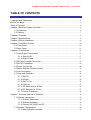
TABLE OF CONTENTS
Copyright and Trademarks...................................................................................................... 2
Before You Begin ..................................................................................................................... 3
Table of Contents ..................................................................................................................... 4
Chapter 1 Switcher System Overview ................................................................................... 6
1.1 Introduction ................................................................................................................. 6
1.2 Packing ....................................................................................................................... 7
Chapter 2 Features .................................................................................................................. 8
Chapter 3 Specifications ......................................................................................................... 9
Chapter 4 Device Installation ................................................................................................ 10
Chapter 5 Front/Rear Panels ................................................................................................ 10
5.1 Front Panel ............................................................................................................... 10
5.2 Rear Panel................................................................................................................ 13
Chapter 6 Connections.......................................................................................................... 15
6.1 Input/Output Connections ....................................................................................... 15
6.1.1 Output LED .................................................................................................... 17
6.1.2 Output Cable ................................................................................................. 17
6.2 IR Pass-Through Connection ................................................................................. 19
6.3 IR EXT Connection .................................................................................................. 20
6.4 Power Connection ................................................................................................... 20
6.5 Matrix Switcher Remote Control ............................................................................ 21
6.6 LAN Connection ....................................................................................................... 21
6.7 Ports and Switchers ................................................................................................. 22
6.7.1 RS-232 ........................................................................................................... 22
6.7.2 RS-485 ........................................................................................................... 24
6.7.3 RxGTx Port .................................................................................................... 25
6.7.4 LAN Port ........................................................................................................ 25
6.7.5 DIP Switchers for 8 Pins .............................................................................. 26
6.7.6 DIP Switcher for 2 Pins ................................................................................ 27
6.7.7 Device ID Settings ........................................................................................ 28
Chapter 7 Switcher Application Software ............................................................................ 30
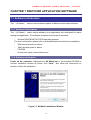
7.1 Software Introduction .............................................................................................. 30
7.1.1 Software Description .................................................................................... 30
7.1.2 Software Activation ....................................................................................... 30
7.1.3 Connect HX-2344Z and PC ......................................................................... 31
7.2 Switcher Configuration ............................................................................................ 32
7.2.1 Main Operation Interface.............................................................................. 33

S E AM L E SS HD B A S E T M AT RI X SW IT CH E R – H X - 2 3 4 4 Z
5
7.2.2 Disconnect Function Key ............................................................................. 35
7.2.3 Options Function ........................................................................................... 36
7.2.4 Communication Protocol/Control Command Code ................................... 36
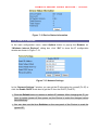
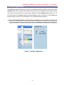
7.3 LAN Web Configuration .......................................................................................... 37
7.3.1 Video Configuration ...................................................................................... 39
7.3.2 Device Status Information ............................................................................ 39
7.3.3 LAN IP Function ............................................................................................ 40
7.3.4 Other Application........................................................................................... 41
Chapter 8 Operation Examples ............................................................................................ 42
Chapter 9 Troubleshooting.................................................................................................... 44
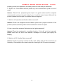
Appendix A Controller ............................................................................................................ 46
Matrix Switcher Remote Controller ............................................................................... 46
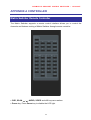
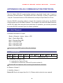
Appendix B Extender ............................................................................................................. 47
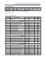
Features .......................................................................................................................... 48
Specifications .................................................................................................................. 49
IR Receiver Cable Directions ........................................................................................ 50
IR Blaster Cable Directions ........................................................................................... 50
HDMI Connector............................................................................................................. 50
Wiring Information for Link Connector ......................................................................... 51
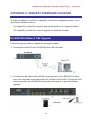
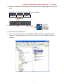
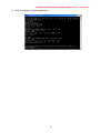
Appendix C HDBaseT Firmware Upgrade .......................................................................... 52
HX-SRPUW HDBaseT F/W Upgrade ........................................................................... 52
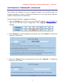
Appendix D Firmware Upgrade ............................................................................................ 55
Appendix E RS-232 Communication Protocol .................................................................... 58
E-1 Host Request ........................................................................................................... 58
E-1.1 Device Byte ................................................................................................... 58
E-1.2 Request Byte ................................................................................................ 59
E-1.3 Index Byte ..................................................................................................... 61
E-1.4 Value Byte ..................................................................................................... 62
E-1.5 CRC Byte ...................................................................................................... 63
E-2 Device ACK Packet ................................................................................................. 64
E-2.1 ACK Type A ................................................................................................... 64
E-2.2 ACK Type B................................................................................................... 65
E-2.3 ACK Type C .................................................................................................. 66
E-2.4 ACK Type D .................................................................................................. 67
E-2.5 ACK Type E................................................................................................... 68

S E AM L E SS HD B A S E T M AT RI X SW IT CH E R – H X - 2 3 4 4 Z
6
CHAPTER 1 SWITCHER SYSTEM OVERVIEW
1.1 Introduction
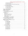
The HX-2344Z Seamless HDBaseT Matrix switcher is a high performance HDMI routing
equipment combining with video and audio. It is used for input/output cross switching of
image signals. Through the extensible accessory devices with RJ-45 connector, it can
transmit images separately to each output equipment for an over long distance about 70
meter by applying HDBaseT zero compression technology. Thereby minimizing signal
attenuation and ensuring high definition, integrating high fidelity graphics and audio signal
output.
The HX-2344Z is used mainly in TV broadcasting projects, multi-media conference halls,
and large display projects, TV teaching and command control centers. It boasts features
of power interruption protection during power surge, LCD display and synchronous and
integrate audio/visual routing functions. HX-2344Z supports 4 HDMI Type A for input and
4 RJ-45 for output connectors. Beside it also supports a RS-232 communication port
enables convenient communication with remote control equipment to configure the
signals.
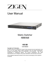
Figure 1-1 HX-2344Z Seamless HDBaseT Matrix Switcher

S E AM L E SS HD B A S E T M AT RI X SW IT CH E R – H X - 2 3 4 4 Z
7
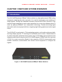
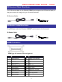
1.2 Packing
HX-2344Z *1
RS-232 Cable *1
Power Cord *1
IR Extended Line *1
Female 1x3 Pole Captive Screw Socket *4
Female 1x5 Pole Captive Screw Socket *2
RJ-45 Cable *1
Remote Controller *1
AAA battery *2
Software CD *1 (Includes User Manual)

S E AM L E SS HD B A S E T M AT RI X SW IT CH E R – H X - 2 3 4 4 Z
8
CHAPTER 2 FEATURES
Truly seamless, glitch-free switching between each input
4 HDMI Inputs with 4 HDBaseT Outputs
Any Input can be route/broadcast to any Output
Supports up to 70 meters zero compression extension via one single CATx cable
Supports Power over Cable
Supports interlaced video to progressive video. (like 1080i => 1080P)
Supports up convert. (like VGA => 1080P@60)
Supports down convert. (like 1080P@60 => VGA)
Supports cross convert. (like 576i@50 => 1080P@60)
HDTV resolution up to 1080p (12Bits)
Compliant with the specification of HDMI
Supports 2 * aspect ratio modes: “FULL” mode, and “1:1” mode. “1:1” mode keeps
the output screen have the same horizontal and vertical ratio as the input video.
That makes the output video has no distortion
Supports 8 * output resolution: VGA, 480P, SVGA, XGA, 720P, SXGA, UXGA,
1080P60
HDCP Compliant
EDID management (Copy from OUT port 1)
IR pass-through supports all IN and OUT ports
IR pass-through supports all kinds of IR frequency band
IR pass-through supports duplex transmission between IN and OUT ports
Support IR remote control
Support IR Mini-Controller to select the input channel through Output configuration
Support RS-232 control
Support RS-485 serial control
Support Ethernet control
Internal universal power supply
Memory control can up to 8 sets
Support High Definition Audio (Dolby TrueHD, Dolby Digital Plus and DTS-HD MA)
Remote controller for operation
Hot pluggable
Auto skips over the power-off and unplugged port
1U rack design

S E AM L E SS HD B A S E T M AT RI X SW IT CH E R – H X - 2 3 4 4 Z
9
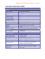
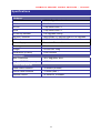
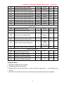
CHAPTER 3 SPECIFICATIONS
Hardware
Input Connector HDMI Type A Female x 4
Output Connector RJ-45 x 4
RS-232 Connector 1 x DB-9 Female
LAN Connector RJ-45 x 1
RS-485 Connector 2
3 Pins Dip Switcher 1
8 Pins Dip Switcher 2
LCD Module 1
Power 100VAC~240VAC, 50/60Hz, internal
Housing Black Aluminum
Mounting Rack mountable (1U-rack-mount kits)
Weight 3950g
Dimensions (LxWxH) 332x482x44 mm (full rack wide without grips)
Multimedia
Max. Resolution 1080P@60Hz
Highest TMDS Frequency 225MHz
Control Information
HDMI Cable Distance
At least 10 meters
Cat.5e Cable Distance
70 meters (Max.)
Baud Rate
9600bps; 8 data bits, 1 stop bit, no parity
Ethernet Protocol
HTTP, DHCP, TCP/IP, ICMP (ping)
Program Control
Web Server, AVM Application
Serial Control Port
RS-232; 9 Pin Female D Type Connector
RS-485: 1x5 Pole Captive Screw
Control Sequence
Matrix
Remote Control
Remote Controller, IR Receiver, IR Blaster
Web Server
LAN, RJ-45

S E AM L E SS HD B A S E T M AT RI X SW IT CH E R – H X - 2 3 4 4 Z
10
CHAPTER 4 DEVICE INSTALLATION
HX-2344Z has a black metallic housing. It can be placed on a sturdy desk directly or
installed on a bracket. See Figure 4-1 below:
Figure 4-1 Mount HX-2344Z on a Standard Bracket with 1U Rack-mount
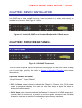
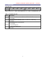
CHAPTER 5 FRONT/REAR PANELS
5.1 Front Panel
Figure 5-1 HX-2344Z Front Panel
The HX-2344Z supports up to 4 Output/Input routing keys on the Front Panel allowing
you to route signal quickly. Also refer to Chapter 8 Operation Examples about below
descriptions.
Operation methods as follows:
“Output Channel” + “Input Channel”
OUT 1~4 keys (output channel): Indicate the Channel 1~Channel 4 for RJ-45 single
output to peripheral displays. You can also use these keys to adjust the status or
access the configurations.
IN 1~4 keys (input channel): Indicate the Channel 1~Channel 4 for HDMI single input.
You can also use these keys to switch the source signals come from the individual
channel or use them to instead of number keys upon memory selections.

S E AM L E SS HD B A S E T M AT RI X SW IT CH E R – H X - 2 3 4 4 Z
11
Resolution: The HX-2344Z Switcher supports you VGA, 480P, SVGA, XGA, 720P,
SXGA, UXGA and 1080P output resolutions. It can convert the input source resolution
to correspond the output resolution.
ALL: This key allows you to set single input channel to all output channels. The usage
of “ALL” key is the same as the output key.
- Press the “ALL” key.
- Select the one of the IN 1~4 keys.
- The selected IN x key will route the input signal to all output channels.
- You can also press the “ALL” key and then press the “OFF” key to disable all
the displayed routing settings.
OFF: Disable the entire output channels. Press one of the OUT x keys that want to be
disabled for the output channel, then press the “OFF” key. Likewise, press the “ALL”
key and then press the “OFF” key to disable all the displayed routing settings. In
addition to routing port menu, press “OFF” key can return to the main screen during
implementing in other menu. You can also press “OFF” key to disable the light of LCD
screen for saving power.
IR: Infrared receiver can receive signals from the Matrix Switcher Remote Controller
EDID: FIX (fix mode) and OUT1 (access the first output channel) selection key.
- FIX mode: The HX-2344Z will supply a set of fixed EDID values to support up to
only 1080P high performance TV.
- OUT1 mode: The HX-2344Z will access the EDID values of high performance TV
that connected to the first output channel, and copy the EDID value to all the input
channels so that the DVD player can support to all the HDTV.
RETURN: Press this key to go back main screen.
PLUG: Press this key to show you the status of all connected input/output jacks on the
rear panel. If the jack is in HPD (hot plug detect), it will appear “O” on the screen.
Alternatively, it will appear “X” specified the jack is unused.
INFO: Press this key to show you the device’s version and ID information.
STO: The “Store Key” saves all current output/input corresponding relations up to 4
sets for a memory control.
- Press the “STO” key firstly.
- Arrange memory location. (Support up to 4 sets of memories, you can select the
memory location through OUT1~OUT4/IN1~IN4.)
- The relation among all settings will be saved in the memory permanently.

S E AM L E SS HD B A S E T M AT RI X SW IT CH E R – H X - 2 3 4 4 Z
12
RCL: The “Retriever Key” retrieves all the settings that are saved in the memory.
- Press the “RCL” key firstly.
- Then make a random to select one of output/input channel key 1~4.
- The system will retrieve the saved all status and implement current status routing
if the previously saving channel is selected.
LCD: LCD display shows current Matrix Switcher and operation status.
Press any keys on the front panel or controller to enable the light of LCD momentarily.
This function cannot be controlled by RS-232 or LAN.

S E AM L E SS HD B A S E T M AT RI X SW IT CH E R – H X - 2 3 4 4 Z
13
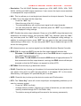
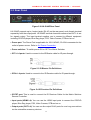
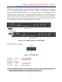
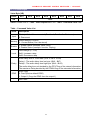
5.2 Rear Panel
Figure 5-2 HX-2344Z Rear Panel
HX-2344Z supports up to 4 output jacks (RJ-45) on the rear panel, each female terminal
separately form the output jacks. HX-2344Z terminal channels numbered as OUT1~4 are
for signals output. The input terminal supplies you to connect to different equipment
including CD/DVD player, Blue Ray player, PS3, Video Camera, STB and so on.
Power port: The Power Port is applicable for 100~240VAC, 50~60Hz connected to the
outlet of power source. Refer to 6.4 Power Connection
.
Power switcher: To switch power ON or OFF the Matrix Switcher.
IR Tx1~4 ports: Used to connect to the IR Blaster cable for IR pass-through.
Figure 5-3 IR Blaster Pin Definitions
IR Rx1~4 ports: Used to connect to the IR Receiver cable for IR pass-through.
Figure 5-4 IR Receiver Pin Definitions
IR EXT port: This is used to connect the IR Receiver Cable for the Matrix Switcher
Remote Controller.
Input ports (HDMI1~4): You can use the HDMI input ports to connect the CD/DVD
player, Blue Ray player, PS3, Video Camera, STB and so on.
Output ports (OUT1~4): You can use the output RJ-45 ports for over long connections
via the extensible accessory devices.

S E AM L E SS HD B A S E T M AT RI X SW IT CH E R – H X - 2 3 4 4 Z
14
RS-232: Use a 9-pin RS-232 cable to connect both computer serial port (COM1 or
COM2) and Matrix Switcher RS-232 communication port, refer to 6.7.1 RS-232. The
computer then can be deployed to control the Matrix Switcher after installing of
application software. Refer to 7.1 Software Introduction for a software control or
Appendix E RS-232 Communication Protocol for an individual configuration.
RS-485: Connection ports allow you to connect/control more than one Matrix product,
refer to 6.7.2 RS-485.
LAN port: Use the RJ-45 connection cable to connect both of the PC and the Matrix
Switcher for an Internet configuration. The entire PCs at the same network can control
the Matrix Switcher through the LAN port. Refer to 6.7.4 LAN Port.
Switchers: The HX-2344Z supports 2 sets of 8 pins DIP switcher and a 3 pins DIP
switcher for connected configurations. For more information, refer to 6.7 Ports and
Switchers
RxGTx: Use the transmission line with RS-232 to connect the remote control PC for a
data transmission between local and remote.
- Rx: Receive RS-232-level signal pin. (data in)
- G: GND
- Tx: Transmit RS-232-level signal pin. (data out)

S E AM L E SS HD B A S E T M AT RI X SW IT CH E R – H X - 2 3 4 4 Z
15
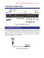
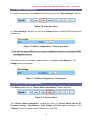
CHAPTER 6 CONNECTIONS
Figure 6-1 HX-2344Z Connections
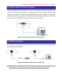
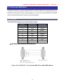
6.1 Input/Output Connections
Use the HDMI connecting cable to connect the Input serial jack (HDMI 1~4) to the HDMI
jack of the Blu-ray/DVD player/graphics workstations/number displays. Use the Cat.5e
cable to connect the output RJ-45 jack (OUT1~4) to the LINK IN jack of Extenders.
Through the Extender, you can extend the connection of projector, video recorder,
displayer or multiplexer to your HX-2344Z.
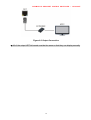
Figure 6-2 Input Connection

S E AM L E SS HD B A S E T M AT RI X SW IT CH E R – H X - 2 3 4 4 Z
16
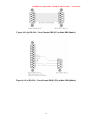
Figure 6-3 Output Connection
All of the output HDTVs’ brands must be the same so that they can display normally.

S E AM L E SS HD B A S E T M AT RI X SW IT CH E R – H X - 2 3 4 4 Z
17
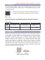
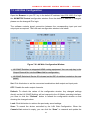
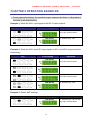
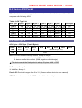
6.1.1 Output LED
HX-2344Z supports HDBaseT output for a long distance signal transmission. Output
connector is RJ-45 jack with two LED indicators. The LED indicators show you the status
of output transmission.
* The left of RJ-45 output jack is specified for HDCP LED (Yellow).
* The right of RJ-45 output jack is specified for LINK LED (Green).
The LED indicators are only designed for the Output – RJ-45 jack of HX-2344Z.
LED Indicators:
LED Off Blink On
LINK
(Green)
No Link Low Power Mode HDBaseT Link
HDCP
(Yellow)
No HDMI Signals - HDCP Encryption
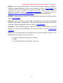
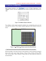
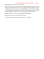
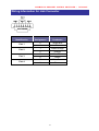
6.1.2 Output Cable
HDBaseT was designed to provide Full HD performance up to 100 meters of Cat.5e or
superior cables. In a typical installation, the cable is stretched to its full length between
the HDBaseT Transmitter device and the HDBaseT Receiver device. However
sometimes, especially, in demonstrations or in a lab environment, the cable is rolled
randomly in small turns for convenience. The randomly rolled UTP cable suffers
additional signal impairments (compared to straight cable) and therefore the maximal
operating reach might be reduced. When a Cat.5e cable is randomly rolled, it is
recommended to limit its length to approximate 50 meters. Rolling a Cat.5e cable around
a 100cm fixed diameter plastic drum has just a minor effect on the FEXT (Far End Cross
Talk) when compared to a fully stretched cable.
Figure 6-4 Output LAN Cable

S E AM L E SS HD B A S E T M AT RI X SW IT CH E R – H X - 2 3 4 4 Z
18
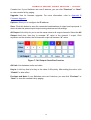
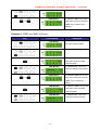
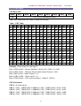
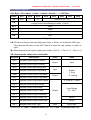
The VS100/VS010 family features as below:
When the VS100/VS010 is in low power mode (LPPF1/2), the sample rate of the PDIF
channel is reduced to 100 KHz. This implies that high data rates may not be used when
the VS100/VS010 is in LPPF.
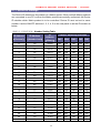
Enables 10.2 Gbps of HDMI 1.4 traffic (including HDCP) and 100Mbps Ethernet in
parallel over a single LAN cable according to the following specifications:
VS100:
Cable Type Range Supported Video
CAT5e/CAT6
100 meters
Most common full HD formats:
- Up to 1080, 60Hz, 36bpp
- Data rates lower than 5.3 Gbps or below
225 MHz TMDS clock
70 meters Ultra HD video formats:
Deep color: 1080p, 60Hz, 48bpp
4K x 2K
Data rates higher than 5.3 Gbps or above
225MHz TMDS clock
CAT6a/CAT7
100 meters
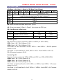
VS010:
Cable Type Range Supported Video
CAT5e/CAT6
60 meters Most common full HD formats:
- Up to 1080, 60Hz, 36bpp
- Data rates lower than 5.3 Gbps or below
225 MHz TMDS clock
CAT6a/CAT7
70 meters
CAT5e/CAT6
35 meters Ultra HD video formats:
- Deep color: 1080p, 60Hz, 48bpp
4K x 2K
- Data rates higher than 5.3 Gbps or above
225MHz TMDS clock
CAT6a/CAT7
40 meters
Full HD support: 1080P@60Hz@48b/pixels, 3D, 4K x 2K

S E AM L E SS HD B A S E T M AT RI X SW IT CH E R – H X - 2 3 4 4 Z
19
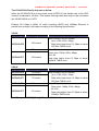
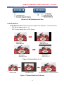
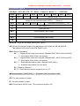
6.2 IR Pass-Through Connection
HX-2344Z provides an IR Receiver cable and IR Blaster cable accessories for IR
pass-through. IR Receiver cable can be connected to RX port. On the other hand, IR
Blaster cable can be connected to TX port on the rear panel.
- Supports you an IR channel to control the player from TV or control the TV from
player.
- Supports all kinds of IR frequency band
- IR pass-through route (channel) is based on HDMI routed (channel)
Figure 6-5 IR Extended Aiming - Multimedia
The Output - IR Tx/Rx are designed on the Extender (HX-SRPUW). IR OUT is
specified for IR Tx, alternatively, IR IN is specified for IR Rx. Refer to Appendix B
Extender

S E AM L E SS HD B A S E T M AT RI X SW IT CH E R – H X - 2 3 4 4 Z
20
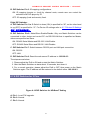
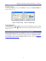
6.3 IR EXT Connection
The Matrix Switcher provides an IR Receiver Cable for more convenient to react to the
Matrix Switcher Remote Controller. If it is difficult for you to aim at IR Receiver on the
front panel due to the location of Matrix switcher, please connect IR Receiver Cable to
the IR EXT port located on the rear panel for optional position.
Figure 6-6 IR EXT Connection
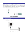
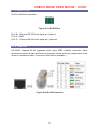
6.4 Power Connection
Use the included power cord to connect the power source from the power port on the
rear panel of HX-2344Z to the outlet.
Figure 6-7 Power Connection
Page is loading ...
Page is loading ...
Page is loading ...
Page is loading ...
Page is loading ...
Page is loading ...
Page is loading ...
Page is loading ...
Page is loading ...
Page is loading ...
Page is loading ...
Page is loading ...
Page is loading ...
Page is loading ...
Page is loading ...
Page is loading ...
Page is loading ...
Page is loading ...
Page is loading ...
Page is loading ...
Page is loading ...
Page is loading ...
Page is loading ...
Page is loading ...
Page is loading ...
Page is loading ...
Page is loading ...
Page is loading ...
Page is loading ...
Page is loading ...
Page is loading ...
Page is loading ...
Page is loading ...
Page is loading ...
Page is loading ...
Page is loading ...
Page is loading ...
Page is loading ...
Page is loading ...
Page is loading ...
Page is loading ...
Page is loading ...
Page is loading ...
Page is loading ...
Page is loading ...
Page is loading ...
Page is loading ...
Page is loading ...
Page is loading ...
-
 1
1
-
 2
2
-
 3
3
-
 4
4
-
 5
5
-
 6
6
-
 7
7
-
 8
8
-
 9
9
-
 10
10
-
 11
11
-
 12
12
-
 13
13
-
 14
14
-
 15
15
-
 16
16
-
 17
17
-
 18
18
-
 19
19
-
 20
20
-
 21
21
-
 22
22
-
 23
23
-
 24
24
-
 25
25
-
 26
26
-
 27
27
-
 28
28
-
 29
29
-
 30
30
-
 31
31
-
 32
32
-
 33
33
-
 34
34
-
 35
35
-
 36
36
-
 37
37
-
 38
38
-
 39
39
-
 40
40
-
 41
41
-
 42
42
-
 43
43
-
 44
44
-
 45
45
-
 46
46
-
 47
47
-
 48
48
-
 49
49
-
 50
50
-
 51
51
-
 52
52
-
 53
53
-
 54
54
-
 55
55
-
 56
56
-
 57
57
-
 58
58
-
 59
59
-
 60
60
-
 61
61
-
 62
62
-
 63
63
-
 64
64
-
 65
65
-
 66
66
-
 67
67
-
 68
68
-
 69
69


Ask a question and I''ll find the answer in the document
Finding information in a document is now easier with AI
Related papers
-
AVLink HX-331616 Owner's manual
-
-
-
-
-
-
-
-
-
Other documents
-
Cable Electronics SW808HD User manual
-
 Zigen HX-88 User manual
-
PTN HDBT44-N User manual
-
clare CM-MT4410-BT-70 User manual
-
SIIG CE-H23E11-S1 Quick start guide
-
Intermec 751G Operating instructions
-
Digitus DS-55500 Quick start guide
-
 Kensence W-HDMI-50TR User manual
-
Altinex MX2414RM User manual
-
CYP DS-MSC User manual

