Page is loading ...

R
WOODBRIDGE
R
WOODBRIDGE
R
WOODBRIDGE
R
WOODBRIDGE
R
WOODBRIDGE
R
WOODBRIDGE
R
WOODBRIDGE
R
WOODBRIDGE
R
WOODBRIDGE
R
WOODBRIDGE
R
WOODBRIDGE
R
WOODBRIDGE
20200307 REV. 3
www.woodbridgebath.com
1
IMPORTANT!
Questions?
SHOWER DOORS:
MBSDC4876
MBSDC6076
TUB DOORS:
MBTDC6062
WOODBRIDGE reserves the right to alter, modify or redesign products at any time without prior
notice for the purpose of product improvement and customer experience. Please refer to
WWW.WOODBRIDGEBATH.COM for the latest product details.
Please Call Customer Support: 562-229-0088. (Monday - Friday 9 AM - 5 PM Pacific Time)
Or Email: [email protected]
SHOWER DOOR
INSTALLATION MANUAL
R
WOODBRIDGE

R
WOODBRIDGE
R
WOODBRIDGE
R
WOODBRIDGE
R
WOODBRIDGE
R
WOODBRIDGE
R
WOODBRIDGE
R
WOODBRIDGE
R
WOODBRIDGE
www.woodbridgebath.com
2
IMPORTANT
•WoodBridge reserves the right to alter, modify, or redesign products at any time
without prior notice for product improvement or functionality.
•Professional installation required. This product should be installed by someone
experienced with the construction requirements for this type of project, the care
necessary to responsibly and safely install, and familiarity with glass installation.
•The safety of all installations is the responsibility of the installer who should be
licensed and bonded.
•To prevent breakage and injury, do not attempt to lift, move, or install the glass
alone. Use an assist and suction cups intended for heavy glass when applicable.
•To prevent breakage and injury, do not lean or push against glass panels.
•The installation of this model requires drilling into the dam/curb/threshold to
properly affix the clip, guide, and threshold. Contact the manufacturer of your
base, or tub with any questions regarding drilling into their product, or consult your
installation professional.
•This model requires minimum 3" dam/curb/threshold width to complete
installation.
•Drawings included in this manual are illustrative only and do not reflect actual
scale.
•No out of plumb adjustment.
•Glass cannot be installed if the overall width of the shower opening is greater than
the width as described for the product.
WARNING FOR TEMPERED GLASS: TO AVOID RISK OF DAMAGE OR INJURY
•Tempered safety glass is designed that when broken, will shatter into thousands of
tiny pieces, greatly reducing the chance of great bodily harm.
•Follow all requirements and recommendations in the instruction manual.
•Perform a thorough inspection of the glass and hardware for any damage prior to
installation.
•Do not install damaged glass.
•Do not install or operate if glass panels have chipped corners, slivered edges, or
any other visual defect. If damage is found contact WoodBridge immediately. If
installed in this state WoodBridge is not responsible for any breakage.
•Do not install glass panels that have been dropped on, or bumped into any
surface harder than itself.
•Improper handling may cause breakage.
While incredibly resistant to direct impact, corners and edges are the most
susceptible to damage, causing breakage. These edges should be protected and
handled with care, never allowed to come into contact with any material harder
than itself, such as tile, stone, metal, or even other glass. A concentrated point of
impact or contact with such material can cause the glass to shatter. Tempered
glass may release all at once, or partially, releasing hours or even days later with
vibration and normal use.
•Incorrect installation of the hardware, rollers, stoppers, or glass may cause
breakage.
Improper installation would include loose hardware, or lack of gaskets between
hardware and glass. Installing out of level or plumb causing extra stress could

R
WOODBRIDGE
R
WOODBRIDGE
R
WOODBRIDGE
R
WOODBRIDGE
R
WOODBRIDGE
R
WOODBRIDGE
R
WOODBRIDGE
R
WOODBRIDGE
www.woodbridgebath.com
3
•Improper use of the product.
Do not place towels or anything else over guide rail. Aggressively opening or
closing the slider may cause trauma to the glass which could lead to breakage.
•Do not attempt to cut tempered glass.
•Always wear safety equipment such as goggles, work gloves, proper footwear
etc... during installation.
•Instruct homeowner on how to conduct periodic inspections and how to
properly maintain the glass and all hardware.
•Consideration should be given when installing tempered glass products in
households with young children or elderly.
PREPARATION
•Thoroughly read the instructions before installing or using the product.
•After boxes and packages are open, before installation, check that all items
from the parts list are there by marking each one off the list.
•Examine the glass and parts for defects or damage.
•Please note that Woodbridge will not replace any missing or damaged items
free of charge after 5 business days or if the product has been installed.
•Building codes vary by location and you should refer to your local building
codes when installing. WoodBridge is not responsible for code compliance and
will not accept returns on that basis.
•Prior to installation ensure that all surfaces are smooth and even. Ensure the
dam/curb/threshold is level side to side and that it has slope/fall in the direction
of the shower pan. Ensure the walls are plumb and the opening measures the
same top and bottom. Ensure that the installation surface is solid and able to
support the weight of the doors.
•Please note that irregular installation surface, round lower corners, or out of
plumb walls will result in serious problems for your installation.
•Some adjustments and drilling/screwing will be necessary throughout
installation.
•Woodbridge shower doors are not designed to be installed on fiber glass
surrounds that have round lower corners or lack of solid mounting surface.
•Glass must never be set down directly on any hard surface. Always use pieces
of wood or thick cardboard to protect lower edge at all times. Leave corner
protectors in place until it is time to remove them

R
WOODBRIDGE
R
WOODBRIDGE
R
WOODBRIDGE
R
WOODBRIDGE
R
WOODBRIDGE
R
WOODBRIDGE
R
WOODBRIDGE
R
WOODBRIDGE
R
WOODBRIDGE
www.woodbridgebath.com
R
WOODBRIDGE
4
IMPORTANT INFORMATION
REGARDING THE INSTALLATION
OF THIS SHOWER DOOR
!
A
B
C
B
A
D
E
F
A.Guide Rail Brackets must be firmly attached to the wall. Installation into a stud is
strongly recommended. All of the guide rail bracket set screws must be accessible
and tightened.
B.Thread Lock must be applied to the set screws in both stoppers. Door-side stopper
must be installed at the proper position to prevent the door from contacting the wall.
D.The Guide Block must be screwed to the threshold and installed square with the
Stationary Glass and Glass Door. Installing the guide block crooked may damage
the bottom edge of the Glass Door and lead to breakage.
C.Roller Wheel Assembly safety set screws: must be accessible and must be
retightened with Thread Lock during installation.
D.Bulb Vinyl Seal must be installed on the closing edge of the Glass Door from
contacting the wall.

R
WOODBRIDGE
WOO
R
WOODBRIDGE
WOO
R
WOODBRIDGE
WOO
www.woodbridgebath.com
R
WOODBRIDGE
5
INSTRUCTIONS THAT, IF IGNORED COULD RESULT IN SERIOUS INJURY OR DEATH
CAUSED BY INCORRECT HANDLING OR INSTALLATION OF THE PRODUCT.
THESE INSTRUCTIONS MUST BE OBSERVED FOR SAFE INSTALLATION!
LICENSED AND INSURED PROFESSIONAL CONTRACTOR IS REQUIRED TO INSTALL
THIS PRODUCT INCLUDING ASSISTANCE OF A SECOND PERSON DURING INSTALLATION
No modifications to the product are allowed. Modifications of any types to the product will result in serious injuries or may cause death.
IMPORTANT: Do not install the handle on to the glass door unl the
instrucon tells you to do so. Never li the glass using the handle. Failure to
do so will result in serious personal injury and could cause damages to the
glass. Professional graded glass sucon cups are highly recommended while
handling extremely heavy glass. This product must be installed on a finished
threshold and against finished walls only. This product is intended for
residenal use only.
Tools
Soft Head
Hammer
Professional-grade
Glass suction cup
Extender Driver Bit
#3 Phillips
Driver Bit
Razor Knife
Silicone
Work Gloves
Safety Glasses
Soft Cloth
or Blanket
Soft Wood
Shim
Phillips
Screwdriver
Pencil
Tape
Measure
Level
Power
Drill
Drill Bit
Ø1/8"
(3mm)
Drill Bit
Ø3/16"
(4mm)
Drill Bit
Ø1/4"
(6mm)
Drill Bit
Ø5/16"
(8mm)
Drill Bit
Ø3/8"
(10mm)
Miter saw
Hacksaw
Painter's Tape

R
WOODBRIDGE
R
WOODBRIDGE
R
WOODBRIDGE
R
WOODBRIDGE
R
WOODBRIDGE
R
WOODBRIDGE
R
WOODBRIDGE
R
WOODBRIDGE
www.woodbridgebath.com
R
WOODBRIDGE
6
1
2
3
4
5
6
7
8
9
2mm
2.5mm
3mm
4mm
5mm
10
11
12
13
14
15
16
17
18

R
WOODBRIDGE
R
WOODBRIDGE
R
WOODBRIDGE
R
WOODBRIDGE
R
WOODBRIDGE
R
WOODBRIDGE
R
WOODBRIDGE
R
WOODBRIDGE
www.woodbridgebath.com
R
WOODBRIDGE
7
x1 x2
Bumper Strip
1 2
x2
3
x1
4
x2
5
x1
6
x1
7
x1
8
x1
9
x2
10
x1
11
x5
12
x1
13
x1
14
x2
15
x2
16
x2
x1
2mm
2.5mm
3mm
4mm
5mm
S
et
17 18
Guide Rail Bracket Glass Door Stopper
Upper Guide Rail
Roller
Handle
Glass Door
Anti-splash Threshold
Side Anti-Water Strip
Screw M4X30
Allen Key
Guide Block
Wall Anchor
Bottom Clamp
Stationary Glass Screw M5X60
Glass Bracket
Safety Pin
Parts List

R
E
R
BRIDGE
R
E
R
WOODBRIDGE
W
R
E
R
WOODBRIDGE
W
WOO
W
www.woodbridgebath.com
R
WOODBRIDGE
8
Model Specific Preparation
±0.0±0.0
±0.0±0.0
No Out-of-Plumb
Adjustment; Verify
threshold and walls
with a level
Threshold must be
level
PANEL
PANEL
DOOR
DOOR
3” minimum
threshold
!
Threshold must be level
NOTE
This model is reversible for right or left-hand door installation. The right-hand door installation is
shown as an example throughout this manual. For the left-hand door installation, simply begin on the
opposite wall and reverse the orientation of the steps shown.
!

R
WOODBRIDGE
R
WOODBRIDGE
R
WOODBRIDGE
R
WOODBRIDGE
R
WOODBRIDGE
R
WOODBRIDGE
www.woodbridgebath.com
R
WOODBRIDGE
9
Fig 1
W
W
90
Wall
W
1.Measure the distance between two finished walls. This distance is marked as W.
Please see Fig 1 for details:

R
WOODBRIDGE
R
WOODBRIDGE
R
WOODBRIDGE
R
WOODBRIDGE
R
WOODBRIDGE
R
WOODBRIDGE
www.woodbridgebath.com
R
WOODBRIDGE
10
d.
W
L
2
2
4
16
a.
b.
c.
4
4
Door End(no holes)
Door End
Panel End
Note: The Glass Brackets have been pre-installed to the roller bar.
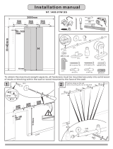
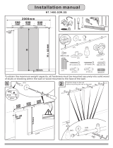
2. Your Upper Guide Rail (4) has been
precut for your Shower model opening
width: 48" or 60" for shower width. If
W-width of your wall-to-wall opening is
equal to the size of your shower model,
it is unnecessary to cut the Upper
Guide Rail and you can continue to
Step 3. If W-width of your wall-to-wall
opening is less than the size of your
Shower model, you will need to cut the
Upper Guide Rail from the end which is
farther from the Glass brackets (16)
holes.
The length to cut off will be L:
L=Subtract W from the size of your
Shower model.
Please see Fig 2 for details.
FOR EXAMPLE
If your wall opening W=47". Your shower
model is 48".
L=48"-47"=1",
You have to cut 1" off from the rail.

R
WOODBRIDGE
R
WOODBRIDGE
R
WOODBRIDGE
R
WOODBRIDGE
R
WOODBRIDGE
R
WOODBRIDGE
www.woodbridgebath.com
R
WOODBRIDGE
11
a. b.
Bracket core
Front
c.
Bracket core screw
d.
e.
f.
g.
2
2
3
4
16
2
3
16
2
2
4
16
39/16"
51/8"
3
3
3. Use the allen key (18) to loose the screw
on the Guide Rail Brackets (2) and Glass
Door Stoppers (3). Slide the Glass Door
Stopper and then the Guide Rail Bracket
to the Guide Rail (4), use the allen key to
tighten the parts to the guide rail
temporarily.
Please see Fig 3 for details.

R
WOODBRIDGE
R
WOODBRIDGE
R
WOODBRIDGE
R
WOODBRIDGE
R
WOODBRIDGE
R
WOODBRIDGE
R
WOODBRIDGE
R
WOODBRIDGE
www.woodbridgebath.com
R
WOODBRIDGE
12
a.
b.
c.
13
14
4. Install Stationary Glass
Loose the screw on Bottom Clamp (13). Disassemble the Bottom Clamp and install it on the
Stationary Glass (14).
Please see Fig 4 for details

R
WOODBRIDGE
R
WOODBRIDGE
R
WOODBRIDGE
R
WOODBRIDGE
R
WOODBRIDGE
R
WOODBRIDGE
R
WOODBRIDGE
R
WOODBRIDGE
www.woodbridgebath.com
R
WOODBRIDGE
13
W
o
od
a.
b.
c.
16
14
Door end of guide rail
High spot of Adjustment Disk bushing
Glass-to-Rail Bracket
Adjustment disk
16
The outer Glass-to-Rail Bracket (#16) disk has an
eccentric bushing for adjustment. Be sure to install both
Glass-to-Rail Bracket disks with the high spot of the
bushing pointed towards the door end of the guide rail.
5. Loose the screws on the Glass Bracket (16),
align the hole of the Glass Bracket to the holes
on the Stationary Glass (14). Secure the Upper
Guide Rail (4) to the Stationary Glass by
fastening the screws on the Glass Bracket.
Please see Fig 5 for details.
ATTENTION:
Never set your glass down directly onto a tile or concrete floor. Always use a piece of wood or cardboard and leave the corner pads on the glass
until it becomes necessary to remove them to protect the bottom edge and the corners of the glass from breakage.

R
WOODBRIDGE
R
WOODBRIDGE
R
WOODBRIDGE
R
WOODBRIDGE
R
WOODBRIDGE
R
WOODBRIDGE
R
WOODBRIDGE
R
WOODBRIDGE
www.woodbridgebath.com
R
WOODBRIDGE
14
a.
b.
14
14
2
rotate disk(s) to level rail
Door end of guide rail
High spot of Adjustment Disk bushing
The Stationary Glass (14) must be
installed to the outside of the Top Guide
6. Place the Stationary Glass Assembly against the wall. Make sure the Stationary Glass and the
Upper Guide Rail (4) are leveled.
Please see Fig 6 for details.

R
GE
R
WOODBRIDGE
W
R
GE
R
WOODBRIDGE
W
R
GE
R
WOODBRIDGE
W
www.woodbridgebath.com
R
WOODBRIDGE
15
Fig 6
Panel end
Door end
Glass-to-Rail Bracket (16)
Guide Rail Bracket (2)
*right-hand door installation shown.
Lower guide rail Raise guide rail

R
WOODBRIDGE
R
WOODBRIDGE
R
WOODBRIDGE
R
WOODBRIDGE
R
WOODBRIDGE
R
WOODBRIDGE
R
WOODBRIDGE
R
WOODBRIDGE
R
WOODBRIDGE
R
WOODBRIDGE
R
WOODBRIDGE
R
WOODBRIDGE
www.woodbridgebath.com
R
WOODBRIDGE
16
a.
b.
14
2
c.
13
d.
e.
f.
7.Slide the Guide Rail Bracket (2) against
the wall, outline the Guide Rail Brackets
position on the wall. Set the Stationary
Glass (14) aside. Remove the Wall Bracket
from the guide rail bracket and place them
to the outlined positions and mark the
drilling holes on the wall. Outline the
position of the Bottom Clamp (13) on the
base as well. Remove the Clamp from the
Stationary Glass and place it back to the
outlined positions, now mark the drilling
holes on the threshold.
Please see Fig 7 for details.
Fig 7
Wall Bracket

R
WOODBRIDGE
R
WOODBRIDGE
R
WOODBRIDGE
R
WOODBRIDGE
R
WOODBRIDGE
R
WOODBRIDGE
R
WOODBRIDGE
R
WOODBRIDGE
www.woodbridgebath.com
R
WOODBRIDGE
17
a. b. c. d.
Screw M5X60
e.
f.
g.
h.
Screw M4X30
12
15
10
12
Screw M5X60
15
8. Drill the holes to the wall per the predrilled position using 8mm(5/16") drill bit and apply silicone
into the holes, insert the Wall Anchors (12). Mount the Wall Bracket of the Guide Rail Bracket (2) to
the wall by using the Screws M5×60 (15).
Drill the holes to the threshold per the predrilled poistion using 8mm (5/16”) drill bit and apply
silicone into the holes, insert the Wall Anchor, mount the Bottom Clamp Plate to the threshold by
using M4x30 screw (10)
Please see Fig 8 for details.
Note:
The other side of the Guide Rail bracket (2) is installed in the same way.
Ø5/16" (Ø8mm)
Ø5/16" (Ø8mm)
Ø5/16" (Ø8mm)
Ø5/16" (Ø8mm)
Ø5/16" (Ø8mm)

R
WOODBRIDGE
R
WOODBRIDGE
R
WOODBRIDGE
R
WOODBRIDGE
R
WOODBRIDGE
R
WOODBRIDGE
R
WOODBRIDGE
R
WOODBRIDGE
www.woodbridgebath.com
R
WOODBRIDGE
18
b.
a.
c.
5
21
5
7
5
7
5
5
7
Attention: Need to loose the small allen screws
before loosing the long allen screw on the roller
9. Attach the two Roller Assemblies (5) to the
Glass Door(7) with the wheels facing outside of
the shower.
Please see Fig 9 for details
Attention:
DO NOT attach the handle to the Door Glass
until instructed.
DO NOT attempt to lift the Glass Door with
the handle as this may result in damage to
the glass and/or serious personal injury. Use
a professional grade glass suction cup and
an assistant.

R
WOODBRIDGE
R
WOODBRIDGE
R
WOODBRIDGE
R
WOODBRIDGE
R
WOODBRIDGE
R
WOODBRIDGE
R
WOODBRIDGE
R
WOODBRIDGE
www.woodbridgebath.com
R
WOODBRIDGE
19
a. b.
c. d.
2
2
16
e.
f.
10. Place the Stationary Glass Assembly back into the designated position. Slide the Guide Rail
Bracket (2) to the two end sides of the Upper Guide Rail(4). Tighten the set screws on the Guide
rail bracket (2) with Allen Key (18) to secure the guide rail to the wall.
Install the Bottom Clamp (13) back to the Stationary Glass(14).
Please see Fig 10 for details.
Note: The other side of the Guide Rail bracket (2) is installed in the same way.

R
ODBRIDGE
OD
R
WOODBRIDGE
WOOD
R
WOODBRIDGE
WOOD
W
W
www.woodbridgebath.com
R
WOODBRIDGE
20
a.
b.
14
14
2
Fig 11
Panel end
Door end
Glass-to-Rail Bracket (16)
Guide Rail Bracket (#2)
*right-hand door installation shown.
Lower guide rail Raise guide rail
/