
Warranty Registration and Inquiry
For product warranty registration, TOTO U.S.A. Inc. recommends online warranty registration. Please visit our web site
http://www.totousa.com.If you have questions regarding warranty policy or coverage, please contact TOTO U.S.A. Inc.,
Customer Service Department, 1155 Southern Road,Morrow, GA 30260 (888) 295-8134 or (678) 466-1300 when calling
from outside of U.S.A.
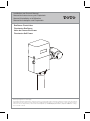
Installation and Owner’s Manual
Manual de Instrucciones y del Propietario
Manuel d’Installation et d’Utilisation
Manual de Instalação e do Proprietário
EcoPower Flush Valve
Fluxómetro EcoPower
Valve de Chasse EcoPower
Fluxómetro Self Power

ENGLISH
2
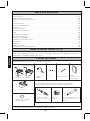
TABLE OF CONTENTS
THANKS FOR CHOOSING TOTO!
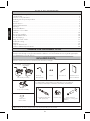
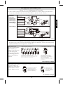
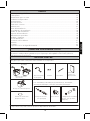
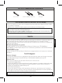
INCLUDED PARTS
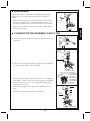
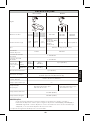
Check to make sure you have all these parts from the package*:
*Appearance of some components may vary depending on the model.
Valve body assembly
Top cover assembly
ScrewsBack-up
Battery Pack
Hex wrench Installation and
Owner's Manual
For TEU1UA(X)12, TEU1LA(X)(12,22),TEU1GA(12,22), TET1UA(X)32,
TET1LA(X)32, TET6LA(X)32, TET1GA32, TET6GA32,
TET6UA(X)32
Vacuum breaker tube
(with spud joint)
Control stop Sweat solder kit
(Escutcheon, covering tube,
Adapter)
Thanks for Choosing TOTO!...................................................................................................................2
Included Parts.............................................................................................................................................2
Common Tools Needed............................................................................................................................3
3............................................................................................................ tcudorp rewopocE eht gnizilaitinI
Features..................................................................................................................................3
Specifications..........................................................................................................................
4
Technical Information.................................................................................................................................5
Warnings..........................................................................................................................................6
Before Installation.......................................................................................................................................6
Installation Procedure...............................................................................................................................7
Test Run.....................................................................................................................................................10
Note to the Installer..................................................................................................................................10
Periodic Maintenance...............................................................................................................................10
Using the Flush Valve.............................................................................................................................11
Troubleshooting.................................................................................................................................12
Warranty.........................................................................................................................................16
Rough-In Dimensions...............................................................................................................................62
Reclaimed Water Specifications..............................................................................................................64
Flush valve
The mission of TOTO is to provide the world with healthy, hygienic and more comfortable
lifestyles. We design every product with the balance of form and function as a guiding principle.
Congratulations on your choice.
TEU1UA(R)(X)
all valves except for
TEU1UA(R)(X)
Notice label
Care & Cleaning........................................................................................................................................10

FEATURES
Fully Automatic and Hygienic
The EcoPower Flush Valve uses an infrared sensor to detect the user using and departing the
fixture, to provide an automatic flush of the fixture after a short delay. No manual operation is
required, improving the experience of use and hygiene of the fixture.
System Protection Timer
When the fixture is not used for 24 hours (12 hours for TEU1LA(R)(X) and TEU1UA(R)(X)) the
protection timer commands the system to flush in order to maintain the trap seal.
Manual Functionality
For maintenance and emergency use, the EcoPower Flush Valve is equipped with a manual
flushing button.
Green Features
Conserves Power
The flushing of the fixture activates a hydropower generator which generates electric power for
the next flush. (See About TOTO’s Hydropower Generator, page 5)
Conserves Water
Two functions help the EcoPower Flush Valve conserve water:
Fuzzy Logic Control
The EcoPower Flush Valve can sense how often and how long the fixture has been used to
deliver the correct amount of water. (See About Fuzzy Logic Control, page 5)
Anti Consecutive Flushing
The EcoPower Flush Valve offers water saving consecutive flush prevention. After a flush, the
valve will not automatically flush again for 10 seconds for urinals and 30 seconds for toilets.
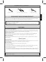
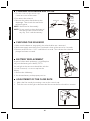
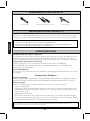
COMMON TOOLS NEEDED
TOTO EcoPower Flush Valve are designed to work for 10 years, under normal conditions, with no
minimum usage required.
Screwdrivers (Phillips and Slotted )
Adjustable wrench
ENGLISH
3
Offset pipe wrench
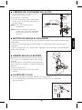
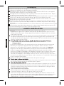
INITIALIZING THE ECOPOWER PRODUCT
It will take approximately 5 minutes after connecting the battery for the electronics to initialize.
This delay is a normal part of startup.
After approximately 30 seconds, the sensor LED will start flashing in 4 second intervals until
the initialization is complete.
Thank you for choosing the latest innovation in low power consumption EcoPower products.
Please note below the duration of time required to initialize the electronics.

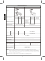
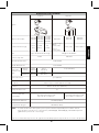
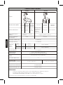
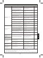
SPECIFICATIONS
1"NPT 3/4"NPT
1-1/4"NPSM
1-1/2"NPSM
7 psi (48 kPa)
Flush Valve type bowl
Wash down flush
Automatic flush every
24 hours of non-use
Model Number
Figure
Control stop inlet
Flush Valve inlet
Flush Valve outlet
Supply water
pressure
Shutoff pressure
Rated Flush Volume
Toilet/Urinal type
Trap seal protection
TET1GAR
TET6GAR
Toilet Urinal
TEU1GAR
Min
Max*
15 psi
(103 kPa)
(Flowing)
15 psi (103 kPa)
125 psi
(862 kPa)
125 psi (862 kPa)
125 psi
(862 kPa)
35 psi
(241 kPa)
1.6 G
(6 L)
1.28 G
(4.8 L)
0.5 G (1.9 L)
Automatic flush every
12 hours of non-use
TEU1LAR
TEU1LAX
TEU1UAR
TEU1UAX
0.125 G (0.47 L)
* Water pressures over 80 psi are not recommended for most plumbing fixtures.
NOTE:
32-104˚F (0-40˚C)
34-104˚F (1-40˚C)
Detection range
from the front
7" (H) x 4-9/16"(W) x 3-3/16"(D)
(178 mm (H) x 115 mm (W) x 81 mm (D))
Dimension of cover
Detection time
Ambient temperature
Water temperature
Within 33-1/2" (850 mm)
6 seconds
The type of fixture determines the minimum pressure required for the valve. Consult
fixture manufacturer for the pressure requirement. TET6LA(R)(X), TET6GAR, and TET6UA(R)(X)
require 24" OR LONGER vacuum breakers. The valve will not have the proper detection range
if you use a shorter vacuum breaker.
0.5 G (1.9L)
fuzzy logic
adj. flush vol.
1.0 G (3.8 L)
typical flush vol.
(Static)
ENGLISH
4
1 G
(3.8 L)
TET1LAR
TET1LAX
TET6LAR
TET6LAX
TET1UAR
TET1UAX
TET6UAR
TET6UAX

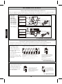
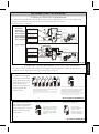
About Fuzzy Logic Control (TEU1GAR only)
High Frequency of Usage Low Frequency of Usage
Less Less Less Less Less LessTypical
Long duration of usage Short Duration of Usage
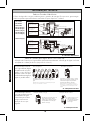
About TOTO's Hydropowered Generator
ot setator enibrut A )1
generate electric
power.
citamotuA ehT )3
Flush Valve uses the
charged power.
si rewop cirtcelE )2
stored in a capacitor.
Sensor eye
Controller
Piston
Water supply
Flush Valve
Coil
Turbine
Cover
1) A turbine rotates to
generate electric
power.
3) The Automatic
Flush Valve uses the
charged power.
2)
Electric power is
stored in a capacitor.
Sensor eye
Controller
Flush Valve
Water supply
Cover
Turbine
Coil
TET1GAR
TET6GAR
TEU1GAR
TET1LA(R)(X)
TET6LA(R)(X)
TEU1LA(R)(X)
TET6UA(R)(X)
TET1UA(R)(X)
TEU1UA(R)(X)
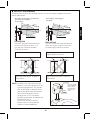
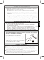
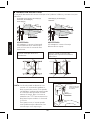
TECHNICAL INFORMATION
The flow of water causes the turbine in the power generator to rotate. This process generates
electric power and enables the automatic Flush Valve to operate. See ill. 1 below.
The Fuzzy Logic Control function automatically adjusts the discharge of water according to the
frequency and duration of usage (see ill. 2 and ill. 3).
Typical
Typical
If the idle time is short, the system assumes frequent use
and the Flush Valve discharges less water.
Examples of high frequency use would be during a lunch
break or an intermission in a movie theatre.
A short duration of use
indicates there may be
less to flush, requiring the
Flush Valve to discharge
less flush water.
If the idle time is long, the system
assumes infrequent use, causing the
Flush Valve deliver a typical quantity of
water for thorough flushing.
Examples of low frequency use would be
during after hours at the office or a slow
day at the park.
The Fuzzy Logic
Control system judges
the frequency of
usage by the idle time
of the fixture and
causes the Flush Valve
to discharge water in
an optimal flushing
pattern.
The Fuzzy Logic Control
system predicts the
quantity of flush water
needed based on the
user's duration of use.
A long duration of use indicates
there may be more to flush,
requiring the Flush Valve to
deliver a typical quantity of flush
water for thorough flushing.
ill. 2 Frequency of Usage
ill. 3 Duration of Usage
ill. 1 Hydropowered Generator
ENGLISH
5
Less

BEFORE INSTALLATION
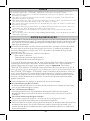
WARNINGS
Please read and adhere to these notes. Failure to do so could
result in personal injury and/or property damage.
Never splash water on the controller. The EcoPower Flush Valve is an electric appliance.
Risk of product malfunction.
Do not strike or kick the EcoPower Flush Valve. Risk of product malfunction or water leakage.
Do not use the EcoPower Flush Valve at temperatures exceeding what local codes or
product specification allow. Risk of product malfunction.
Do not place an item in a room with high humidity such as shower area or sauna. Risk of
product malfunction.
Never attempt to disassemble, reassemble, repair or modify the EcoPower Flush Valve
unless you are a professional. Risk of product malfunction and electric shock.
Do not use standard vacuum breaker or control stop with reclaimed water flush valve.
Do not use petroleum based products or pipe sealants, doing so could damage product and
cause water damage.
ENGLISH
6
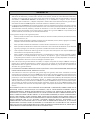
IMPORTANT: Plumbing installation must be in accordance with applicable codes and
regulations. Water supply lines must be sized to provide an adequate volume of water for
each fixture. Flush all waterlines prior to operation.
Prior to installing your Flush Valve, install the items listed below:
Bowl fixture/Urinal fixture
Drain line
Water supply line
The supply piping to these devices must be securely anchored to the building structure to
prevent the installed device moving during use. Prevent marring to the exposed surface
during installation.
IMPORTANT: Purge all air from the supply lines before connecting
flush valve to the bowl. Trapped air in supply lines may crack the china.
Avoid damaging the surface of the infrared sensor while unpacking.
For Toilet Flush Valve:
The toilet Flush Valve may not function if toilet seat or lid cover are left upright and block the
sensor.
For Urinal Flush Valve:
The urinal Flush Valve is designed for optimal performance with a washout urinal, but a
siphon jet urinal may be substituted. Blowout urinals are not recommended.
The detection range of the infrared sensor is shown on p.15.
To prevent valve malfunction, do not install a handrail or any other object within the detection
range of the sensor. Do not install the Flush Valve where sensor faces a mirror, stainless steel
wall, other highly reflective surfaces or another infrared sensor.
For Reclaimed Water Flush Valve:
Only use reclaimed water angle stop and vacuum breaker.
Toilet and urinal Flush Valves are not interchangeable, check the model number on the label to
make sure you have the correct type. Toilet Flush Valve model numbers begin with ‘TET’ and
Urinal Flush Valve model numbers begin with ‘TEU’.
Except for TET6GAR, TET6UA(R)(X) and TET6LA(R)(X), install the Flush Valve so the control
stop is no less than 11-1/8” (282mm) above the top of the bowl/urinal. For TET6GAR,
TET6UA(R)(X) and TET6LA(R)(X), install the Flush Valve such the control stop is 27” (685.8mm)
above the bowl/urinal. see local codes for special requirements.

D
O
N
O
T
U
S
E
P
E
T
R
O
L
E
U
M
-
B
A
S
E
D
S
E
A
L
A
N
T
S
A
T
T
E
N
T
I
O
N
!
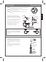
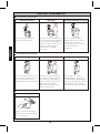
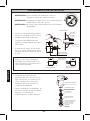
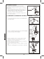
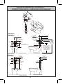
INSTALLATION PROCEDURE
Escutcheon
Covering tube
Adapter
Min.4-1/4"(107mm)
Max.5-1/4"(133mm)
For sweat solder
Vacuum breaker
Tube nut
Spud nut
Slip gasket
Rubber gasket
Escutcheon
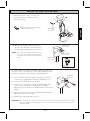
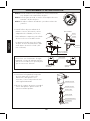
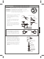
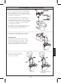
1. Install the control stop using an
appropriate size escutcheon and a
sweat solder
adapter kit, if applicable.
Thread sealing
compounds should be
used on male NPT threads only.
The distance from center of the control
stop to center of the Flush Valve
should fall within 4-1/4" to
5-1/4"(107mm to 133mm).
For use with a left water supply, attach
the sensor top cover in the opposite
direction so that the sensor will be at
the front.
2. Determine the length of vacuum
breaker tube to join the Flush Valve
and fixture spud. If required, cut the
vacuum breaker tube to the proper
length.
3. Assemble the spud nut assembly to
the fixture spud. Hand tighten spud
nut to fixture.
NOTE: For retrofit installation, remove the old Flush Valve
after shutting off the control stop.
NOTE: For reclaimed water, do not use standard vacuum
breaker or control stop.
NOTE: Do not use petroleum based products or pipe
sealants.
Control stop
Right Water Supply Left Water Supply
ENGLISH
7
Friction washer

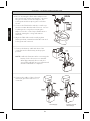
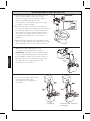
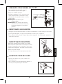
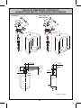
INSTALLATION PROCEDURE
White
Battery
TEU1UA(R)(X)
all valves except for
TEU1UA(R)(X)
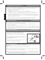
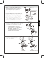
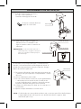
4. Prior to inserting the Flush Valve tailpiece into
the control stop, make sure that the o-ring is in
the groove at the end of the tailpiece, the
locking nut and the snap ring are located as
shown.
5. Connect the Flush Valve with the control stop
and the vacuum breaker tube. Exercise care not
to damage the o-ring when inserting the
tailpiece into the control stop. If lubrication is
needed, wetting the o-ring with water is
sufficient.
6. Align the Flush Valve and securely tighten
fixture spud nut, vacuum breaker tube nut and
locking nut with a wrench.
7. Connect the battery cable with that of the
controller and set the battery at the proper
position.
8. Connect the cables of the solenoid
valve and generator with those of
controller.
ENGLISH
8
NOTE:
It will take 5 minutes after connecting the
battery for the electronics to initialize.
After approximately 30 seconds, the
sensor LED will flash in 4 second intervals
until the initialization completes.

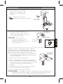
INSTALLATION PROCEDURE
Hex wrench
Escutcheon
Joint tube
Pipe connection
Pipe connection
Pipe connection
Cap
Control stop
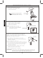
9. Fasten the sensor top cover to body
assembly with the supplied screws
and hex wrench.
The Flush Valves are preset for fixture volume as marked on
the valve carton. The valve does not require adjustment for
variation in water pressure within its operating range.
11. To set the Flush Valve for proper operation, open the
control stop completely by using the adjusting screw.
12. Activate the Flush Valve several times.
13. In the case of excessive flow rate, gradually adjust the
control stop towards the closed position using the
adjusting screw, until there is suitable water flow into the
fixture.
14. The cap for the control stop should be placed after final
adjustments have been made.
15. Tighten the cap firmly with a wrench.
WARNING: Do not open the control stop to the point where the flow from the Flush Valve exceeds
the flow capability of the fixture. In case of a valve failure, the water must not overflow
from the fixture.
10. Before the supply water is turned on,
be sure all water leaks are eliminated
by tightening all the pipe connections.
NOTE: If for any reason it becomes necessary
to remove the control stop, make sure
the water is shut off at the main supply
valve.
ENGLISH
9
inside the top cover.
Protect the wire connections

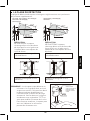
TEST RUN
NOTE TO THE INSTALLER
PERIODIC MAINTENANCE
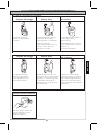
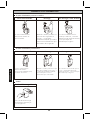
1. For Toilet: Sit on the toilet seat.
For Urinal: Stand within two feet from the front of the Flush Valve.
2. Stay there for 6 seconds or more and then leave the toilet seat or the urinal. The valve
should automatically flush, immediately for urinals and after 3 seconds for toilets.
3. Press the manual flushing button for 2 seconds and make sure the valve flushes properly
and the sensor red light of the sensor is on. To correct overflow from a urinal Flush Valve,
adjust the control stop clockwise.
4. Recheck all the pipe connections for water leaks. If the Flush Valve is not operating
properly following the test run consult the Troubleshooting section on p.12.
After the Flush Valve unit has been installed correctly, please explain to your customer how to
use it and tell them to observe the following instructions:
1. Do not put any object in front of the sensor window which could obstruct the sensor,
causing it to malfunction.
2. In case of any trouble, consult the troubleshooting section on p.12. If you lack the necessary
skills required or have difficulty following the directions for installation, maintenance, repairs,
troubleshooting or adjustments of the product, do not proceed without help from a qualified
person to assist you.
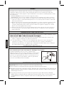
Please check your EcoPower Flush Valve at least once a month according to the following
instructions to avoid risk of property damage.
Check the piping to see whether there is any leakage.
Press the manual flushing button and make sure the
sensor red light is on for 2 seconds to see if the genera-
tor performs properly or not.
If the red light is not on, check the generator to see if
any debris is clogged up at the turbine.
ENGLISH
10
After connecting the battery, the initialization process takes 5 minutes. After approximately 30
seconds, the sensor LED will start flashing in 4 second intervals until the initialization is
complete. Please wait before starting the Test Run.
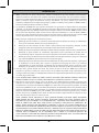
CARE & CLEANING
IMPORTANT! Do not scratch the sensor or faceplate when cleaning.
Avoid using any cleaning materials that may scratch the surface.
Never use polishing powder, detergent that includes coarse particles, thinners, benzene,
acids, alkaline detergents, or nylon scrub brushes.
To safely clean the surface, wipe it using a dampened soft cloth with diluted dishwashing
detergent and dry it with another soft cloth. If this does not adequately clean the surface,
wipe the area with a neutral detergent and wet cloth.

USING THE FLUSH VALVE
Using the Toilet Flush Valve
Infrared Sensor Flushing
The infrared sensor detects
a user of the toilet.
When the user stays in place
longer than 6 seconds then
moves away, the controller
sends a signal to the operating
unit to automatically trip the
Flush Valve after 3
seconds delay.
Flushing Every 24 hours
If toilet is not used for 24 hrs,
the system automatically
flushes as a maintenance
and hygienic precaution.
Use the manual flush button
for maintenance and/or
emergencies.
Using the Urinal Flush Valve
Infrared Sensor
Common
Manual Flushing Button
Flushing
Flushing Every 12 hours
The infrared sensor detects
a user standing within
2 ft (600 mm) of the front of
the urinal.
When the user stays in place
longer than 6 seconds then
moves away, the controller
sends a signal to the operating
unit to automatically trip
the flush. (No delay)
If urinal is not used for 12 hrs
the system
automatically
flushes
as a maintenance
and hygienic precaution.
ENGLISH
11

Clean the small hole in the
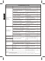
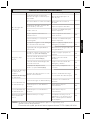
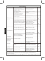
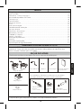
TROUBLESHOOTING
No water comes
from the
Flush Valve
Water does not
stop flowing
The discharge
volume is too small
The discharge
volume is too much
The flow rate is too
low
A red light in the
sensor window blinks
The main valve in water supply
line or the control stop is shut off
One or more cables not
connected
The surface of the glass in front
of the infrared sensor is dirty
The glass is broken
There is a reflective surface in
front of the sensor
The infrared sensor or the
solenoid is out of order
The small holes in the solenoid
diaphragm are clogged
Hydropower generator is clogged
The small hole in the piston is
clogged (not for TEU1UA(R)(X))
The sealing area of the piston is
dirty (not for TEU1UA(R)(X))
The sealing area of the solenoid
diaphragm is dirty
The screw of the control stop is
not adjusted properly
Water supply pressure is too low
(below rated minimum pressure)
The control stop is not open
enough
The flow rate is too
high
The control stop is not adjusted
properly
The battery is weak
Open the main valve or the
control stop
Check all cable connections
Clean the surface of the
glass
Contact distributor for
replacement
Remove the reflective
surface in front of sensor
Contact distributor for
replacement
Clean the small hole in the
diaphragm and filter
Service hydropower
generator
piston
Clean the sealing area of
the piston
Clean the sealing area of
the diaphragm and filter
Adjust the discharge quantity
by the screw of the control
stop
Consult with a plumbing
contractor
Adjust the control stop
properly
Adjust the control stop
properly
-
-
-
-
15
-
Piston u-packing is damaged
(not for TEU1UA(R)(X))
Inspect & replace if
necessary
-
Ref.PageSuggested ActionPossible Cause
NOTE: Do not dismantle parts of the Flush Valve which are not specified in the
Problem
14
-
13
13
14
13
14
14
14
14
troubleshooting guide.
If you need further assistance, please call TOTO Technical Support at (888) 295-8134.
ENGLISH
12
Check voltage with multimeter,
if below 2.6 V, contact TOTO
for replacement battery.

ENGLISH
13
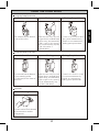
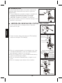
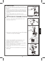
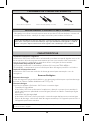
1. Turn the screw of the control stop clockwise to turn off
the water.
2. Take out the piston assembly (except for TEU1UA(R)(X))
or take out the filter for TEU1UA(R)(X).
Control stop
Top cover
Cap
Piston assembly
TET1LA(R)(X)
TET6LA(R)(X)
TEU1LA(R)(X)
TEU1GAR
Top cover
Cap
Filter
TEU1UA(R)(X)
Cap
Flow
regulator
Sealing area
Small hole
Filter
Piston U-packing
DISASSEMBLY
CLEANING PISTON ASSEMBLY AND FILTER
TET6GAR
TET1GAR
3. Check the small hole in the piston to see if it is clogged
with debris. Insert a small wire to unclog hole if needed.
4. Check the filter to see if it is clogged with debris and
gently brush it clean.
5. Check the sealing area of the piston and clean it if it is
dirty.
6. Check the U-packing for cracks or damage.
If the whole valve needs to be removed from the water
supply for servicing, please be aware of the cautions
below:
1. Be careful not to lose or tear the friction washer at the
outlet connection to the vacuum breaker tube nut. To
maintain a proper seal, replace the washer if necessary.
2. When re-installing the valve to the water supply, avoid
pinching the o-ring.
Hex wrench
TET6UA(R)(X)
TET1UA(R)(X)

ENGLISH
14
Sealing area
Small holes
Diaphragm
Filter
Solenoid
O-ring
Plunger
Cap
Sensor unit
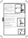
CLEANING DIAPHRAGM AND FILTER
BATTERY REPLACEMENT
ADJUSTMENT OF THE FLOW RATE
1. Adjust the flow rate by the turning screw on the control stop.
2. Turn the screw to the right to decrease the flow rate and turn to the left to increase.
1. Make sure the batteries are properly placed and cables are connected.
2. With water supply turned off, place your hand in front of the sensor for 6 seconds.
3. Remove and listen for a “click” sound after 3 seconds. This indicates the solenoid
plunger has been activated.
1. Turn the screw on the control stop
clockwise to turn off the water.
2. Disconnect the solenoid.
3. Remove the solenoid and take out the
diaphragm. Then check the small holes
and sealing area.
NOTE: See below for disassembly.
NOTE: Do not stretch or alter the shape of
the spring in the solenoid valve in
any way. It will void the warranty.
A special lithium back-up battery is used. Replace
only with the battery provided by TOTO.
If a red light in the sensor window blinks with the
cycle of 4 seconds, it is time to replace the
battery.
1. Remove the old battery.
2. Set the new battery at the proper position.
Control stop
CHECKING THE SOLENOID
Spring

ENGLISH
15
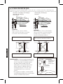
DETECTION RANGE
Another infrared sensor.
PRECAUTION
PRECAUTION
Control stop
Elbow
Wall flange
The detection range of the infrared sensor is set at the factory and does not need
further adjustment.
DO NOT place the infrared sensor
of one Flush Valve so that it is in
line with the sensor of another
Flush Valve sensor.
DO NOT place the infrared sensor in
front of a mirror, stainless steel wall,
or other highly reflective surface.
NOTE: In some cases, the valve may not
detect a user if the toilet seat is left
in an upright position. This can be
due to the rough-in dimension or
gap of the open front commercial
seat. Please lower the seat or
arrange with a TOTO or other
plumbing contractor to change the
height of the valve.
The sensor can have trouble
detecting users wearing black
clothes in some conditions.
Infrared sensor of the automatic
Flush Valve.
Infrared sensor of the automatic
Flush Valve.
Mirror, stainless steel wall or other
highly reflective surface.
Use chrome plated
elbow to adjust the
height of TOTO
EcoPower Flush
Valve from the
fixture.
TET6LA(R)(X), TET6UA(R)(X)
TET6GAR
TET1GAR, TET1LA(R)(X), TET1UA(R)(X)
TEU1GAR, TEU1UA(R)(X)
TEU1LA(R)(X)
33-1/2"
(850mm)
15°
Max 19-11/16”
(Max 500mm)
33-1/2"
(850mm)
20°
Max 21-1/4”
(Max 550mm)

ENGLISH
16
WARRANTY
1. TOTO warrants its electronic flush valves, faucets and soap dispensers (“Product”) to be free from defects in
materials and workmanship during normal use when properly installed and serviced, for a period of three (3) years
from date of purchase. This limited warranty is extended only to the ORIGINAL PURCHASER of the Product and is
not transferable to any third party, including but not limited to any subsequent purchaser or owner of the Product.
This warranty applies only to TOTO Product purchased and installed in North, Central and South America.
2. TOTO’s obligations under this warranty are limited to repair, replacement or other appropriate adjustment, at
TOTO’s option, of the Product or parts found to be defective in normal use, provided that such Product was properly
sa snoitcepsni hcus ekam ot thgir eht sevreser OTOT .snoitcurtsni htiw ecnadrocca ni decivres dna desu ,dellatsni
ni strap ro robal rof egrahc ton lliw OTOT .tcefed eht fo esuac eht enimreted ot redro ni yrassecen eb yam
connection with warranty repairs or replacements. TOTO is not responsible for the cost of removal, return and/or
reinstallation of the Product.
4. In order for this limited warranty to be valid, proof of purchase is required. TOTO encourages warranty registration
upon purchase to create a record of Product ownership at http://www.totousa.com is required. TOTO encourages
registration upon purchase and failure to register will not diminish you r limited warranty rights.
5. THIS WARRANTY GIVES YOU SPECIFIC LEGAL RIGHTS. YOU MAY HAVE OTHER RIGHTS WHICH VARY
FROM STATE TO STATE, PROVINCE TO PROVINCE OR COUNTRY TO COUNTRY.
6. To obtain warranty repair service under this warranty, you must take the Product or deliver it prepaid to a TOTO
service facility together with proof of purchase (original sales receipt) and a letter stating the problem, or contact
a TOTO distributor or products service contractor, or write directly to TOTO U.S.A., INC., 1155 Southern Road,
Morrow, GA 30260 (888) 295 8134 or (678) 466-1300, if outside the U.S.A. If, because of the size of the Product
or nature of the defect, the Product cannot be returned to TOTO, receipt by TOTO of written notice of the defect
esoohc yam OTOT ,esac hcus nI .yreviled etutitsnoc llahs )tpiecer selas lanigiro( esahcrup fo foorp htiw rehtegot
to repair the Product at the purchaser’s location or pay to transport the Product to a service facility.
THIS WRITTEN WARRANTY IS THE ONLY WARRANTY MADE BY TOTO. REPAIR, REPLACEMENT OR OTHER APPROPRIATE
ADJUSTMENT AS PROVIDED UNDER THIS WARRANTY SHALL BE THE EXCLUSIVE REMEDY AVAILABLE TO THE ORIGINAL
PURCHASER. TOTO SHALL NOT BE RESPONSIBLE FOR LOSS OF THE PRODUCT OR FOR OTHER INCIDENTAL, SPECIAL
OR CONSEQUENTIAL DAMAGES OR EXPENSES INCURRED BY THE ORIGINAL PURCHASER, OR FOR LABOR OR OTHER
COSTS DUE TO INSTALLATION OR REMOVAL, OR COSTS OF REPAIRS BY OTHERS, OR FOR ANY OTHER EXPENSE NOT
SPECIFICALLY STATED ABOVE. IN NO EVENT WILL TOTO’S RESPONSIBILITY EXCEED THE PURCHASE PRICE OF THE
PRODUCT. EXCEPT TO THE EXTENT PROHIBITED BY APPLICABLE LAW, ANY IMPLIED WARRANTIES, INCLUDING THAT
OF MERCHANTABILITY OR FITNESS FOR USE OR FOR A PARTICULAR PURPOSE, ARE EXPRESSLY DISCLAIMED. SOME
STATES DO NOT ALLOW LIMITATIONS ON HOW LONG AN IMPLIED WARRANTY LASTS, OR THE EXCLUSION OR
LIMITATION OF INCIDENTAL OR CONSEQUENTIAL DAMAGES, SO THE ABOVE LIMITATION AND EXCLUSION MAY NOT
APPLY TO YOU.
3. This warranty does not apply to the following items:
a. Damage or loss sustained in a natural calamity such as fire, earthquake, flood, thunder, electrical storm, etc.
b. Damage or loss resulting from any accident, unreasonable use, misuse, abuse, negligence, or improper
care, cleaning, or maintenance of the Product.
c. Damage or loss resulting from sediments or foreign matter contained in a liquid soap system.
ro/dna hsrah a ni tcudorP eht fo noitallatsni morf ro noitallatsni reporpmi morf gnitluser ssol ro egamaD .d
hazardous environment, or improper removal, repair or modification of the Product.
e. Damage or loss resulting from electrical surges or lightning strikes or other acts which are not the fault of
TOTO or which the Product is not specified to tolerate.
f. Damage or loss resulting from normal and customary wear and tear, such as gloss reduction, scratching or
fading over time due to use, cleaning practices or water or atmospheric conditions, including but not limited
to, the use of bleach, alkali, acid cleaners, dry (powder) cleaners or any other abrasive cleaners or the use
of metal or nylon scrubbers.
Page is loading ...
Page is loading ...
Page is loading ...
Page is loading ...
Page is loading ...
Page is loading ...
Page is loading ...
Page is loading ...
Page is loading ...
Page is loading ...
Page is loading ...
Page is loading ...
Page is loading ...
Page is loading ...
Page is loading ...
Page is loading ...
Page is loading ...
Page is loading ...
Page is loading ...
Page is loading ...
Page is loading ...
Page is loading ...
Page is loading ...
Page is loading ...
Page is loading ...
Page is loading ...
Page is loading ...
Page is loading ...
Page is loading ...
Page is loading ...
Page is loading ...
Page is loading ...
Page is loading ...
Page is loading ...
Page is loading ...
Page is loading ...
Page is loading ...
Page is loading ...
Page is loading ...
Page is loading ...
Page is loading ...
Page is loading ...
Page is loading ...
Page is loading ...
Page is loading ...

62
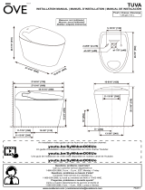
ROUGH-IN DIMENSIONS / BOSQUEJO /
ROBINETTERIE BRUTE / DIMENSÕES APROXIMADAS
Inlet supply 1” NPT
TET1LA(X)32
TET1GA32
TET1UA(X)32
TET6LA(X)32
TET6GA32
TET6UA(X)32
Inlet Supply
1” NPT
4-9/16”
(115mm)
3-3/16” (81mm)
4-1/4”
(108mm)
3-3/16”
(81mm)
** ADA 2010 Section 609
Grab Bar
** Ø1-1/4”~2”
(32~51mm)
** 1-1/2” (38mm)
* Min.11-1/8” (282mm)
11-1/2” (292mm) (w/o cutting)
36” (915mm)
(** Min.33”~Max.36”
(840~915mm) )
ADA Grab bar combination
Max. 29”(737mm)
(for Ø1-1/4” Grab bar)
Max. 28-3/4”(730mm)
(for Ø1-1/2” Grab bar)
Max. 28-1/4”(718mm)
(for Ø2” Grab bar)
4-3/4”±1/2”
(120±13mm)
1-1/2”
NPSM
7”
(178mm)
Min. 2-1/4” (57mm)
** Min. 1-1/2”
(38mm)
* Check local codes
* Check local codes
4-1/4”
(108mm)
Inlet Supply
1" NPT
Min. 2-1/4”
(57mm)
4-3/4”±1/2”
(120±13mm)
4-9/16”
(115mm)
1-1/2”
NPSM
7”
(178mm)
* 27”
(686mm)
Inlet Supply
1” NPT

63
ROUGH-IN DIMENSIONS / BOSQUEJO /
ROBINETTERIE BRUTE / DIMENSÕES APROXIMADAS
Min. 2-1/4"
(57mm)
Inlet supply
3/4” NPT
TEU1LA(X)12, 22
TEU1GA12, 22
TEU1UA(X)12
Inlet supply
3/4” NPT
4-9/16”
(115mm)
4-1/4"
(108mm)
3-3/16”
(81mm)
4-3/4”±1/2”
(120±13mm)
* 11-1/2”
(292mm)
7”
(178mm)
* Check local codes
1-1/2”
NPSM

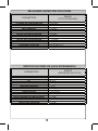
CHLORIDE ION CONCENTRATION < 600mg/L
PH 5.8~8.6
FREE CARBONATE < 50mg/L
LANGELIER'S INDEX > -3.00
NITRATE ION CONCENTRATION < 60mg/L
CONDUCTIVITY < 250mS/m
SULFATE ION CONCENTRATION < 100mg/L
RESIDUAL CHLORINE CONCENTRATION < 2mg/L
HYDROGEN SULFIDE GAS should not exist
SUSPENDED SOLIDS < 5mg/L
RANGE
(TOTO STANDARD)
PARAMETERS
CONCENTRACIÓN DE IONES DE CLORURO
< 600mg/l
PH
5.8~8.6
CARBONATO LIBRE < 50mg/l
ÍNDICE DE LANGELIER > -3.00
CONCENTRACIÓN DE IONES DE NITRATO < 60mg/l
CONDUCTIVIDAD < 250mS/m
CONCENTRACIÓN DE IONES DE SULFATO
< 100mg/l
CONCENTRACIÓN DE CLORO RESIDUAL
< 2mg/l
GAS DE ÁCIDO SULFHÍDRICO
no debe existir
SÓLIDOS EN SUSPENSIÓN
< 5mg/l
RANGO
(ESTÁNDAR DE TOTO)
PARÁMETROS
RECLAIMED WATER SPECIFICATIONS
ESPECIFICACIONES DE AGUA REGENERADA
64

CONCENTRATION D’IONS CHLORURE
< 600 mg/L
PH
5,8~8,6
CARBONATE LIBRE
< 50 mg/L
INDICE DE LANGELIER
> -3,00
CONCENTRATION D’IONS NITRATE
< 60 mg/L
CONDUCTIVITÉ
< 250 mS/m
CONCENTRATION D’IONS SULFATE
< 100 mg/L
CONCENTRATION DE CHLORE RÉSIDUEL
< 2 mg/L
SULFURE D’HYDROGÈNE
Aucune
SOLIDES EN SUSPENSION
< 5 mg/L
PLAGE
(NORMES DE TOTO)
PARAMÈTRES
CONCENTRAÇÃO DE ÍONS CLORETO
< 600 mg/L
PH
5,8~8,6
CARBONATO LIVRE
< 50 mg/L
ÍNDICE DE LANGELIER
> -3,00
CONCENTRAÇÃO DE ÍONS NITRATO
< 60 mg/L
CONDUTIVIDADE
< 250 mS/m
CONCENTRAÇÃO DE ÍONS SULFATO
< 100 mg/L
CONCENTRAÇÃO DE CLORO RESIDUAL
< 2 mg/L
GÁS SULFETO DE HIDROGÊNIO
não deve existir
SÓLIDOS SUSPENSOS
< 5 mg/L
PARÂMETROS
INTERVALO
(PADRÃO DA TOTO)
SPÉCIFICATIONS DE L'EAU RÉCUPÉRÉE
ESPECIFICAÇÕES DE ÁGUA RECUPERADA
65
Page is loading ...
Page is loading ...
Page is loading ...
-
 1
1
-
 2
2
-
 3
3
-
 4
4
-
 5
5
-
 6
6
-
 7
7
-
 8
8
-
 9
9
-
 10
10
-
 11
11
-
 12
12
-
 13
13
-
 14
14
-
 15
15
-
 16
16
-
 17
17
-
 18
18
-
 19
19
-
 20
20
-
 21
21
-
 22
22
-
 23
23
-
 24
24
-
 25
25
-
 26
26
-
 27
27
-
 28
28
-
 29
29
-
 30
30
-
 31
31
-
 32
32
-
 33
33
-
 34
34
-
 35
35
-
 36
36
-
 37
37
-
 38
38
-
 39
39
-
 40
40
-
 41
41
-
 42
42
-
 43
43
-
 44
44
-
 45
45
-
 46
46
-
 47
47
-
 48
48
-
 49
49
-
 50
50
-
 51
51
-
 52
52
-
 53
53
-
 54
54
-
 55
55
-
 56
56
-
 57
57
-
 58
58
-
 59
59
-
 60
60
-
 61
61
-
 62
62
-
 63
63
-
 64
64
-
 65
65
-
 66
66
-
 67
67
-
 68
68


Ask a question and I''ll find the answer in the document
Finding information in a document is now easier with AI
in other languages
- français: Toto TET1LA32-CP Guide d'installation
- español: Toto TET1LA32-CP Guía de instalación
- português: Toto TET1LA32-CP Guia de instalação
Related papers
-
Toto CT449CFG-01 Installation guide
-
-
-
-
-
-
-
Toto TET1UA32#CP Installation guide
-
-
Toto BN Installation guide
Other documents
-
 OVE Decors TUVA Installation guide
-
Toro Jar Top Valve Diaphragm (53804) Installation and User's Guide
-
vitapur VSRF-9 User manual
-
American Standard 6072121 Owner's manual
-
 IBBL FR-600 User manual
-
American Standard SMGOPIS.002 Installation guide
-
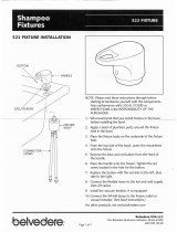 Belvedere 522A-14 Operating instructions
-
Sloan 3250407 Installation guide
-
Sloan 3325412 Installation guide
-
Zurn Z6000AV-WS1-DF Installation guide


