ATTIC LADDER INSTALLATION INSTRUCTIONS
MODELS:
S224P, S254P, AS226P, AS256P, AL226P, AL256P, CS224P, CS224I, CS254P, CS254I, CL224P,
CL224I, CL254P, CL254I, L224P, L254P, S305P, CS305P, L305P, CL305P, AL228P, AL258P
Before you start installing your new Louisville Ceiling Mounted Folding Attic Ladder, you must read and
understand the following:
1. For residential use only. Not for use in a commercial or industrial setting
2. Installation requires two people.
3. Check the ceiling height to make sure the ladder length is correct. If the ladder is too short, return it to the
point of purchase for an exchange. Under no circumstance is any folding attic ladder to be used when the ceiling–to–
floor measurement exceeds the maximum ceiling height as indicated for the Ceiling Mounted Folding Attic Ladder you
are installing (See “Max Ceiling Height” column in table 2, page 3).
4. This folding attic ladder is completely assembled and is ready for installation. Do not disassemble it to install.
5. The springs on this folding attic ladder are under pressure. Do not attempt to remove or replace before installation.
6. Prior to installation, verify that all fasteners are properly tightened. Re–check these periodically after initial installation.
7. Make sure there is no wiring or piping that the saw or drill can come in contact with during installation.
8. Opening or standing on the folding attic ladder’s climbing sections prior to properly fastening to ceiling joists could
cause serious bodily injury.
9. Verify that the unit meets local building codes and that the intended area of installation is of sufficient strength to be
used for a walking or working surface.
10. If the home has roof trusses, do not cut the ceiling joists without consulting an engineer for approval.
11. Before installation, read all the instruction labels on the folding attic ladder.
12. Improper installation could result in serious bodily injury.
13. Do not attempt to open the door prior to installation.
14. Only use 16d nails or ¼” x 3” lag screws (not included) for the permanent installation step.
15. Follow the “Adjust The Ladder Length” instructions on Step 3 for proper trimming instructions.
16. Annually lubricate (spray silicon recommended) pivot points of right and left folding arm mechanism
(power arm assembly) to provide smooth, long–lasting operation.
WARNING
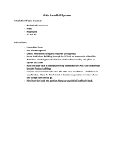
Included with your Folding Attic Ladder
NO. ITEM QTY.
1
Pull cord – 36”
1
2 Support Straps 4
3 16d nails 8
4 Installation Instructions 1
5
Roofing nails – ⁄”
8
6
**Aluminum feet
2
7
** ¾” Bolts
2
8
** ¼” Lock nuts & washers
2
9
+Eyebolt, nut & washer
1
10
+Pole hook
1
**Aluminum models | + Everest models
TABLE 1
ATTIC LADDER SERIES NAME AND MODEL NUMBER CROSS REFERENCE
WOOD ALUMINUM
Series Models Series Models
Premium
S224P S254P L224P
L254P Summit
AS226P AS256P AL226P
AL256P
Champion
CS224P CS254P CL224P CL254P Everest AL228P AL258P
CS224I CS254I CL224I CL254I
Big Boy S305P CS305P L305P CL305P
MATERIALS REQUIRED
[1.] Stepladder [2.] Hammer [3.] Adjustable wrench [4.] Tape measure [5.] Hand saw [6.] Hack saw
[7.] Drill [8.] Drill bit ⁄”,¼” [9.] Phillips screw driver [10.] (12) ¼” x 3” lag screws or 16d nails [11]. Shims
STEP 1: PRELIMINARY INSTALLATION INSTRUCTIONS
A. Attach four E–Z Hang temporary support straps to the frame. Refer to figure 3 and instructions listed below.
• Place the folding attic ladder on the floor with the door opening on your right–hand side.
• Using the roofing nails and straps provided, attach one strap using two nails on the outside of the attic ladder frame at
the extreme right hand corner near the door stop block.
• Attach the second strap opposite the first strap on the far outside frame.
• The third and fourth straps should be positioned on the door hinge side near each corner opposite the door opening.
B. Position one person up in the attic, and position one person in the room below. When using a step ladder make sure
ladder is fully open, all feet firmly supported and user’s weight and materials does not exceed the load rating of the
ladder.
C. The person in the room below will need to raise the attic ladder into the rough opening and position the attic ladder’s
door frame flush with the ceiling surface.
D. The person in the attic should then bend the metal E–Z Hang strapping at the four corners of the attic ladder frame
over the adjoining ceiling joists and nail through the metal strapping using four of the 16d nails provided to temporarily
suspend the attic ladder.
CAUTION: This is only a temporary connection, NEVER climb on ladder in this condition.
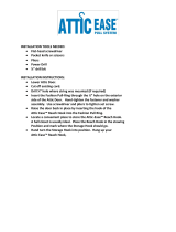
E. Carefully open attic ladder door but do not unfold the climbing section until indicated in step 3. Place the frame on the
door hinge side of the ladder up against the header and center side to side in the rough opening. Temporarily secure to
header with 16d nail. Make sure frame is flush with ceiling before nailing (figure 4, next page).
F. Center and square the opposite side of attic
ladder frame using shims. Ensure ladder
frame is square by measuring diagonals of
the frame within ⁄”. Secure other sides of
ladder frame to ceiling joists with remaining
three 16d nails (figure 4).
STEP 2: PERMANENT
INSTALLATION
A. Install fasteners at the 12 locations shown
in figure 5 for permanent installation.
Either ¼” x 3” lag screws or 16d nails
should be used. Install shims when
necessary to fill any gaps between the door frame and rough opening. Make sure to install the fasteners in the holes
provided in the corner brackets and pivot plates.
NOTE: When using lag screws first drill ¼” diameter holes through the frame at each location to prevent splitting and
follow with ⁄” pilot holes in the ceiling joist facilitate installation of the lag screw.
B. WARNING: Never use deck or sheetrock screws for permanent installation.
Installation instructions for wood models and for aluminum models
Read instructions and warnings completely
before starting
IMPORTANT: DO NOT OPEN FOLDING ATTIC LADDER
UNTIL INSTRUCTED TO IN STEP NUMBER 3.
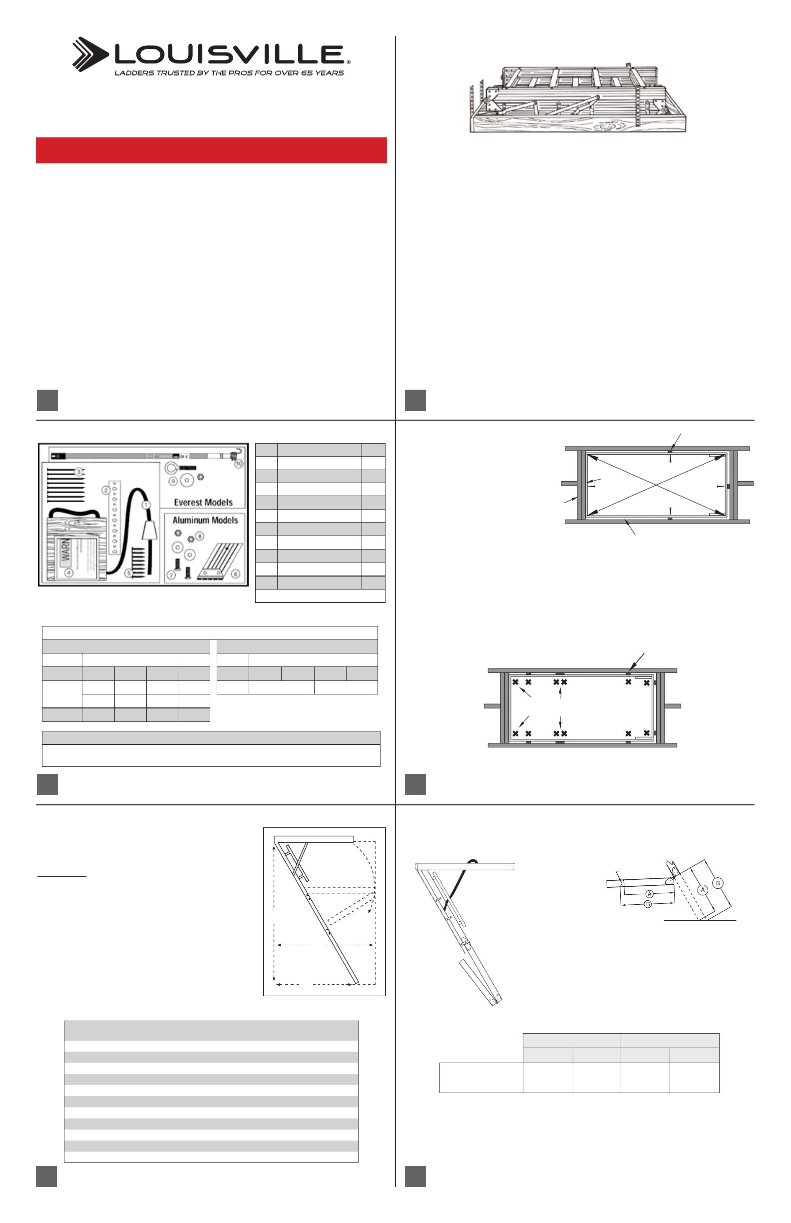
Folding Attic Ladder Location:
Allow ample room for the swing clearance and the landing space of
the folding attic ladder when it is opened (see figure 2 and table 2).
Locate the folding attic ladder rough opening so that when you enter
the storage area, you will have adequate head clearance.
You must have a rough opening as shown for your model in table 2. If
not, proceed to the appendix for framing instructions.
MODEL
ROUGH
OPENING
MAX. CEILING
HT. “A”
LANDING
SPACE* “B”
SWING
CLEARANCE “C”
S224P, AS226P, CS224P, CS224I
22 ½” x 54” 8’ 9” 63” 66”
S254P, AS256P, CS254P, CS254I
25 ½” x 54” 8’ 9” 63” 66”
L224P, AL226P, CL224P, CL224I
22 ½” x 54” 10’ 71” 75”
L254P, AL256P, CL254P, CL254I
25 ½” x 54” 10’ 71” 75”
S305P
30” x 60” 8’ 9” 63” 66”
CS305P
30” x 54” 8’ 9” 60” 69”
L305P
30” x 60” 10’ 71” 75”
CL305P
30” x 54” 10’ 1” 67” 79”
AL228P
22 ½” x 63” 12’ 85” 87”
AL258P
25 ½” x 63” 12’ 85” 87”
*When installed at maximum ceiling height
TABLE 2
B
LANDING SPACE
C
SWING CLEARANCE
A
CEILING
HEIGHT
RANGE
FIGURE 2
FIGURE 3
FIGURE 5
Pivot
Plate
Corner
Bracket
Shim
STEP 3: ADJUST LADDER LENGTH
A. Carefully unfold ladder to the ground rotating bottom section behind middle section (figure 6). Press down on
top and middle sections of the ladder to ensure the power arms are fully extended before taking measurements for trimming
your ladder.
B. With a straight edge, measure distances from middle section to
floor, for both A & B lengths (figure 7).
WOOD MODELS: Proceed to “C”
ALUMINUM MODELS: Skip to page 7 “Additional steps
for aluminum models only”
C. Record A & B values in table 3 for both rails.
D. Transfer these dimensions to the bottom section of the ladder right and left rails and draw a cutting line
between the two points. Trim bottom section to length using wood saw (figure 7).
Proceed to “Check the length after making your cuts” on page 8...
FIGURE 7
CUTTING
LINE
FIGURE 6
LEFT RAIL RIGHT RAIL
A B A B
Measurement to floor
TABLE 3 (Wood models only)
FIGURE 1: All models
Door hinge Door opening
Door hinge end
Shim
Header
Frame
Rough opening
FIGURE 4
2
1
3
4
5
6