
PIO-16/16B(PC)H
Digital I/O Board with Opto-Isolation
User’s Guide

PIO-16/16B(PC)H i
Copyright
Copyright 1997 CONTEC Co., LTD. ALL RIGHTS RESERVED
No part of this document may be copied or reproduced in any form
by any means without prior written consent of CONTEC Co., LTD.
CONTEC Co., LTD. makes no commitment to update or keep
current the information contained in this document. The
information in this document is subject to change without notice.
All relevant issues have been considered in the preparation of this
document. Should you notice an omission or any questionable
item in this document, please feel free to notify CONTEC Co.,
LTD.
Regardless of the foregoing statement, CONTEC assumes no
responsibility for any errors that may appear in this document nor
for results obtained by the user as a result of using this product.
Trademarks
MS, Microsoft, MS-DOS and Windows are trademarks of Microsoft
Corporation. Other brand and product names are trademarks of their
respective holder.

PIO-16/16B(PC)Hii
Product Configuration
- PIO-16/16B(PC)H Board...1
- User’s Guide (this booklet)...1
Unpacking:
This board is specially packed in an anti-static bag to prevent
damage in shipping.
Check the contents to make sure that you have everything listed
above. If you do not have all the items, contact your distributor
or CONTEC group office where you purchased.
Note!
Do not remove the board from its protective packaging until the
computer case is open and ready for installation. Electrical static
can cause damage to electrical components.

PIO-16/16B(PC)H iii
Table of Contents
Copyright............................................................................i
Trademarks ........................................................................i
Product Configuration ..................................................... ii
1. Introduction .............................................................1
About the PIO-16/16B(PC)H Board.............................1
Features.........................................................................1
Function ........................................................................2
Limited Three-Year Warranty......................................3
How to Obtain Service..................................................3
Liability.........................................................................3
About the Manual.........................................................4
2. Board Setup .............................................................5
Component Locations........................................................5
Setting I/O Addresses .......................................................6
Setting Method..............................................................7
Setting Interrupt Levels...................................................8
Setting Method..............................................................8
Selecting power supply...................................................10
3. External Connection ................................................11
Interface Connector.........................................................11
Connecting the Interface Connector..........................11
Interface Connector Pin Assignment.........................12
Input Circuit and Output Circuit...................................13
4. I/O Port Bit Assignment .......................................... 15
I/O Port Bit Assignment .................................................15
Input Port Bit Assignment.........................................15
Output Port Bit Assignment ......................................16
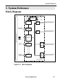
5. System Reference.................................................... 17
Block Diagram.................................................................17
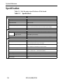
Specification....................................................................18

PIO-16/16B(PC)Hiv
6. Appendix................................................................ 19
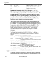
A. Interrupts on the IBM PC/AT and compatible
computers........................................................................19
Interrupt Levels and Vectors......................................20
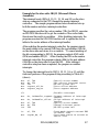
How to Enable the Interrupt Function......................22
Information about setting up the interrupt
environment................................................................22
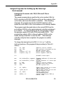
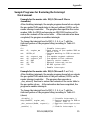
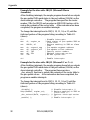
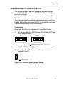
Sample Programs for Setting up the Interrupt
Environment...............................................................25
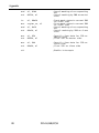
Restoring the Interrupt Environment.......................30
Sample Programs for Restoring the Interrupt
Environment...............................................................31
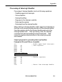
Processing of Interrupt Handler................................33
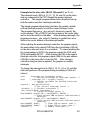
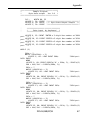
B. LSI Recovery Time .....................................................36
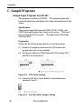
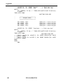
C. Sample Programs.......................................................38
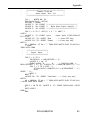
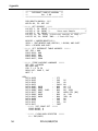
Sample Input Program in Q-BASIC..........................38
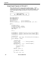
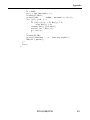
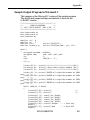
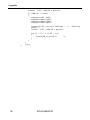
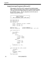
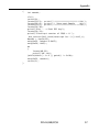
Sample Input Program in Microsoft C.......................42
Sample Output Program in Q-BASIC .......................44
Sample Output Program in Microsoft C....................49
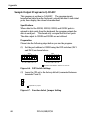
Sample Interrupt Program in Q-BASIC....................51
Sample Interrupt Program in Microsoft C................56
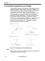
D. Protection Against Excess Voltage............................58
7. Index ..................................................................... 59

PIO-16/16B(PC)H v
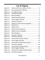
List of Figures
Figure 2.1. Names and Factory Defaults of Parts........................ 5
Figure 2.2. Recommended I/O Addresses................................... 6
Figure 2.3. I/O Address Setting .................................................. 7
Figure 2.4. Disabling Interrupts.................................................. 8
Figure 2.5. Interrupt Settings....................................................... 9
Figure 2.6. Sample Interrupt Settings ......................................... 9
Figure 2.7. Power Supply Selecting.......................................... 10
Figure 3.1. Interface Connector.................................................11
Figure 3.2. Interface Connector Pin Assignments..................... 12
Figure 3.3. Input Circuit........................................................... 13
Figure 3.4. Output Circuit......................................................... 14
Figure 4.1. Input Port Bit Assignment ...................................... 15
Figure 4.2. Output Port Bit Assignment.................................... 16
Figure 5.1. Block Diagram....................................................... 17
Figure 6.1. Interrupt Controllers............................................... 20
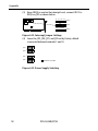
Figure 6.2. DIP Switch Settings................................................ 38
Figure 6.3. Function Select Jumper Setting .............................. 38
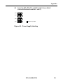
Figure 6.4. Power Supply Selecting.......................................... 39
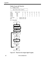
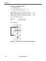
Figure 6.5. Flowchart for Sample Input Program...................... 40
Figure 6.6. DIP Switch Settings................................................ 44
Figure 6.7. Function Select Jumper Setting .............................. 44
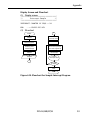
Figure 6.8. Power Supply Selecting.......................................... 45
Figure 6.9. Flowchart for Sample Output Program................... 46
Figure 6.10. DIP Switch Settings................................................ 51

PIO-16/16B(PC)Hvi
Figure 6.11. Function Select Jumper Setting .............................. 51
Figure 6.12. Interrupt Jumper Settings........................................ 52
Figure 6.13. Power Supply Selecting.......................................... 52
Figure 6.14. Flowchart for Sample Interrupt Program................ 53
Figure 6.15. Examples of Anti-Surge Measures.......................... 58
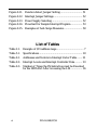
List of Tables
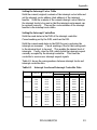
Table 2.1. Example of I/O address range ..................................... 7
Table 5.1. Specifications............................................................ 18
Table 6.1. Addresses and Vectors in Interrupt Vector Table ....... 21
Table 6.2. Interrupt Levels and Interrupt Controller Data.......... 23
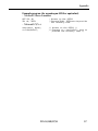
Table 6.3. Number of Times the IN Instruction must be Executed
for the 2EFh Port After Accessing the LSI................ 36

Introduction
PIO-16/16B(PC)H 1
1. Introduction
About the PIO-16/16B(PC)H Board
With an on board isolated 12VDC power supply, PIO-16/16B(PC)H
is a 16 channel isolated digital input and output interface board for
the IBM PC/AT and compatible computers. It can also be installed
into a CONTEC I/O expansion unit.
Features
- Photo-Insulated input/outputs providing improved noise
resistance
- Up to 16 (8 signals x 2 groups) input signals
- Up to 16 (8 signals x 2 groups) output signals
- Two input signals can also generate interrupt requests
- Up to 35VDC, 100mA per signal, max. output ability
- On board has an isolated 12VDC power supply for driving the
photo-isolation devices. Therefore you can select to use either
the on board 12VDC for your application or an external power
supply to drive the photo-isolation devices.

Introduction
PIO-16/16B(PC)H2
Function
- Input
This board installed on a personal computer (PC) inputs up to 16
digital signals in groups each consisting of eight signals from an
external device and passes them to the PC. The PC accesses this
board for input through the two arbitrarily configurable input ports.
When the IN instruction is executed to read data through any of
these input ports, the buffer gate corresponding to that input port
opens to receive the group of digital signals from the external
device. The signals sent to the PC at this time have negative logic.
Since the two signals among the 16 input signals are user-
assignable as interrupt inputs of the PC, the user can use them as
interrupt request signals.
- Output
This board writes up to 16 digital signals in groups each consisting
of eight signals to the external device. The PC accesses the board
for output through the two arbitrarily configurable output ports.
When the OUT instruction is executed to write data to any of these
output ports, the latch circuit corresponding to that output port
holds the data. The digital signals are then electrically insulated
by the photocoupler and output to the connected external device as
a group of signals via the transistor. The signals output to the
external device at this time have negative logic. The data in the
latch circuit remains intact until the OUT instruction is executed
again.

Introduction
PIO-16/16B(PC)H 3
Limited Three-Year Warranty
CONTEC Interface boards are warranted by CONTEC Co., LTD. to
be free from defects in material and workmanship for up to three
years from the date of purchase by the original purchaser.
Repair will be free of charge only when this device is returned
freight prepaid with a copy of the original invoice and a Return
Merchandise Authorization to the distributor or the CONTEC group
office, from which it was purchased.
This warranty is not applicable for scratches or normal wear, but
only for the electronic circuitry and original boards. The warranty
is not applicable if the device has been tampered with or damaged
through abuse, mistreatment, neglect, or unreasonable use, or if the
original invoice is not included, in which case repairs will be
considered beyond the warranty policy.
How to Obtain Service
For replacement or repair, return the device freight prepaid, with a
copy of the original invoice. Please obtain a Return Merchandise
Authorization Number (RMA) from the CONTEC group office
where you purchased before returning any product.
* No product will be accepted by CONTEC group without the
RMA number.
Liability
The obligation of the warrantor is solely to repair or replace the product.
In no event will the warrantor be liable for any incidental or
consequential damages due to such defect or consequences that arise
from inexperienced usage, misuse, or malfunction of this device.

Introduction
PIO-16/16B(PC)H4
About the Manual
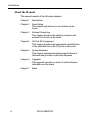
This manual consists of the following chapters :
Chapter 1 Introduction
Chapter 2 Board Setup
This chapter explains how to set switches on the
board.
Chapter 3 External Connection
This chapter describes the interface connector and
external I/O circuits on the board.
Chapter 4 I/O Port Bit Assignment
This chapter describes the assignments and definitions
of the individual bits in the I/O ports on the board.
Chapter 5 System Reference
This chapter summarizes hardware specifications of
the board and provides circuit block diagrams.
Chapter 6 Appendix
This appendix provides a variety of useful reference
information on the board.
Chapter 7 Index

Board Setup
PIO-16/16B(PC)H 5
2. Board Setup
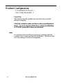
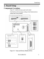
Component Locations
Figure 2.1. identifies the major parts on the board.
Note that the switch and jumper settings in the illustration below
indicate their factory defaults.
Figure 2.1. Names and Factory Defaults of Parts

Board Setup
PIO-16/16B(PC)H6
Setting I/O Addresses
This board is an I/O device controlled by input/output instructions
from by the personal computer. I/O devices include those built-in
the personal computer and expansion boards. I/O addresses are
numbers for distinguishing individual I/O devices. The I/O
address assigned to each I/O device is a four-digit hexadecimal
number, such as 0300H, used to identify that I/O device.
In general, each expansion board is controlled by using a range of
consecutive I/O addresses. Of these consecutive I/O addresses,
the first value is the I/O base address of the expansion board.
This board uses consecutive I/O addresses for the two ports.
Note!
The PC/AT and compatibles operate hardware devices by executing
I/O instructions on I/O address in a range of [0000H to FFFFH].
On these PCs, however, specific I/O addresses are used or reserved
by the system for the CRT, keyboard, and other controls as shown in
the address map found in their technical manual. That is, the user
cannot uses these system-assigned I/O addresses.
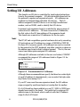
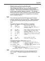
Although I/O addresses available to the user are limited, CONTEC
recommends the ranges of I/O addresses listed in Figure 2.2. for
use by this board.
Recommended I/O addresses
*300H to *31FH
*700H to *71FH
*B00H to *B1FH
*F00H to *F1FH (* : Any value from 0 to F)
Figure 2.2. Recommended I/O Addresses
Although these recommendations specify the three low-order digits
of each I/O address (in hexadecimal), you can select the high-order
digit freely from among 0 to F.
If your PC uses more than one expansion board, the I/O address
range occupied by each board must not overlap that for another.
If a LAN board has been installed on your PC, 300H to 31FH have
already been used for the board. Be careful not to assign an I/O
address range to this board, which conflicts with the I/O address
range for the LAN board.

Board Setup
PIO-16/16B(PC)H 7
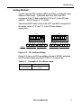
Setting Method
Use the on-board DIP switches (SW1 and SW2) to set the I/O base
address of this board. Individual bits in the SW1 and SW2
correspond to the 15 high-order bits (A15 to A1) in the I/O base
address. Set A0 always to "0" (OFF).
The ON and OFF states of bits in the SW1 and SW2 correspond to
the binary values of "1" and "0" in the I/O base address,
respectively.
A7 A6 A5 A4 A3 A2 A1 A0
Binary
Hexadecimal
0 0 0 0
0
0 0 1 1
3
0 0 0 0
0
0 0 0 0
0
A15 A14 A13 A12 A11A10 A9 A8
1
2
3
4
5
6
7
8
O
F
F
SW1
1
2
3
4
5
6
7
8
O
F
F
SW2
Figure 2.3. I/O Address Setting
Figure 2.3. shows an I/O base address setting of 0300H, assigning
the I/O address range specified in Table 2.1. to this board.
Table 2.1. Example of I/O address range
Functions to be used General-purpose I/O function
I/O addresses 0300H to 0301H
to be occupied (2 ports)

Board Setup
PIO-16/16B(PC)H8
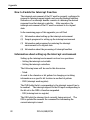
Setting Interrupt Levels
This board can use signals, such as two digital signals among 16
input signals, as interrupt request signals. These signals are used
to issue interrupt requests to the PC, making the interrupt functions
of the PC available. Use the on-board jumper (JP1) to set interrupt
levels.
To disable interrupts, use lead strapping connectors to prevent input
signals from being connected to specific levels.
To enable interrupts, use the on-board jumper (JP1) to set interrupt
levels. The interrupt levels set for this board are IRQs 3 to 7, 9 to
12, 14, and 15. Set those not used for the PC and for any other
board. Up to two levels of interrupt request signals can be
assigned, corresponding to input signals on a one-to-one basis.
Notes!
(1) When using interrupts, set interrupt levels which are not used
for any other resource.
(2) Do not plug or unplug any strapping connector on the JP1
when power has been supplied to the PC (or I/O expansion
unit) on which this board has been installed.
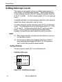
Setting Method
Use the on-board jumper (JP1) to set interrupt levels.
Disabling Interrupts
10
JP1
IRQ
SIG
IRQ
11 12 14 15
9 3 4 5 6 7
1
2
Figure 2.4. Disabling Interrupts

Board Setup
PIO-16/16B(PC)H 9
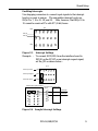
Enabling Interrupts
Use strapping connectors to connect input signals to the interrupt
levels you want to assign. The assignable interrupt levels are
IRQs 3 to 7, 9 to 12, 14, and 15. Note, however, that IRQs 10 to
15 cannot be used on PCs with XT (8-bit) buses.
JP1
I02 (4)
I00 (2)
IRQ
IRQ
1 2
9 3 4 5 6 7
1 0 1 1 1 2 1 4 1 5
Figure 2.5. Interrupt Settings
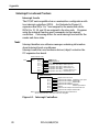
Example : To connect SIG1(I02) from the interface board to
IRQ10 on the PC/AT as an interrupt request signal,
set the JP1 as shown below :
JP1
IRQ
SIG
IRQ
Interrupt level
Interrupt signal
Interrupt level
IRQ
IRQ
Connection
cable
External I/O
SIG1(I02)
SIG2(I00)
IBM PC/AT (input module)
10
11
12
14
15
9
3
4
5
6
7
1
2
9
3
4
5 6
7
1 0
1 1
1 2
1 4 1 5
Figure 2.6. Sample Interrupt Settings

Board Setup
PIO-16/16B(PC)H10
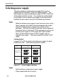
Selecting power supply
The photo-insulation circuits need power supply that cannot be
supplied directly from the PC system, for isolation purpose. This
board equips an on board isolated power supply (12VDC, 250mA) for
driving photo-insulation circuits. You can select to use this internal
power supply or use an external power supply for driving the photo-
insulation circuits in unit of two ports (16 channels) per common.
Notes!
- When the internal power supply is used, the input section of this
board consumes up to 64mA current maximum and the output
channel switching section consumes up to 16mA current
maximum. Note that the output current that can be supplied to
the external device is therefore 170mA maximum in case you use
internal power supply for all the input and output channels.
- Never use the isolated on board 12VDC together with an
external power supply. That may damage the isolated 12VDC
supply.
Setting method
Jumpers JP3 to JP6 are used to select the power supply for photo-
insulation circuits. Refer following table for details.
1 2 3
GND
JP4
1 2 3
JP3
+12V
GND
JP4
JP3
+12V
GND
JP6
1 2 3
JP5
+12V
GND
JP6
1 2 3
+12V
JP5
Output Port 0
Output Port 1
Supply to
Input Port 0
Input Port 1
Use Internal Power
(Factory defaults)
Use External Power
Figure 2.7. Power Supply Selecting
Notes!
- Default setting is using internal power supply.
- These jumpers must be set in pairs.

External Connection
PIO-16/16B(PC)H 11
3. External Connection
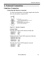
Interface Connector
Connecting the Interface Connector
To connect an external device to this board, plug the cable from the
device into the interface connector (CN1).
Figure 3.1. Interface Connector
Optional Cables
Flat cable with 37-pin D-SUB connectors at either end:
- PCB37P-1.5 (1.5m)
- PCB37P-3 (3m)
- PCB37P-5 (5m)
Shielded cable with 37-pin D-SUB connectors at either end:
- PCB37PS-0.5P (0.5m)
- PCB37PS-1.5P (1.5m)
- PCB37PS-3P (3m)
- PCB37PS-5P (5m)
Flat cable with a 37-pin D-SUB connector at one end:
- PCA37P-1.5 (1.5m)
- PCA37P-3 (3m)
- PCA37P-5 (5m)

External Connection
PIO-16/16B(PC)H12
Shielded cable with a 37-pin D-SUB connector at one end:
- PCA37PS-0.5P (0.5m)
- PCA37PS-1.5P (1.5m)
- PCA37PS-3P (3m)
- PCA37PS-5P (5m)
Optional Accessories
Screw Terminal : EPD-37
Termination Panel : DTP-3(PC)
Termination Panel : DTP-4(PC)
Signal Monitor for Digital I/O : CM-32(PC)E
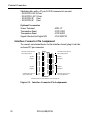
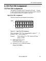
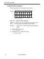
Interface Connector Pin Assignment
To connect an external device to this interface board, plug it into the
on-board 37-pin connector.
1
2
3
4
5
6
7
8
9
10
11
12
13
14
15
16
17
18
19
N0
*I 00
I 01
*I 02
I 03
I 04
I 05
I 06
I 07
I 10
I 11
I 12
I 13
I 14
I 15
I 16
I 17
P0
N.C.
20
21
22
23
24
25
26
27
28
29
30
31
32
33
34
35
36
37
N1
O 00
O 01
O 02
O 03
O 04
O 05
O 06
O 07
O 10
O 11
O 12
O 13
O 14
O 15
O 16
O 17
P1
+0 port
(Input)
+1 port
(Input)
+0 port
(Output)
+1 port
(Output)
Common minus pin for
+0/+1 output port
Common plus pin for
+0/+1 input port
Common plus pin for
+0/+1 output port
Common minus pin for
+0/+1 intput port
*I00 and *I02 are also used as interrupt signals
Figure 3.2. Interface Connector Pin Assignments

External Connection
PIO-16/16B(PC)H 13
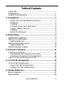
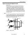
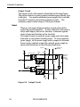
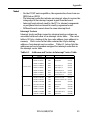
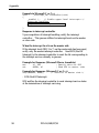
Input Circuit and Output Circuit
Input Circuit
The input circuit of this board is illustrated in following Figure.
The on-board photocouplers isolate internal input circuits from
outside devices. The input channels are to be connected with
current sinking output signals. You need an additional power
supply that is isolated from the PC system to drive these insulation
circuits. When you use a 12VDC power (internal or external),
each input channel will consumes about 4mA current; when 24VDC
external power supply is selected, each input channel will consumes
about 8mA current.
Note!
You cannot connect an external power supply and in the mean time
select to use internal isolated power. To use an external power
supply, set the power supply select jumpers for External Power in
pair and then connect the external power supply as shown with
dotted lines in the following illustration.
Vcc
5.1k
Ω
Vcc
5.1kΩ
JP5
JP6
+12V
Board
Photocoupler
Input
Pin
External
Device
External
Power
Supply
DC12V
~24V
Plus
Common
Input
Pin
3kΩ
Photocoupler
3kΩ
Figure 3.3. Input Circuit
Page is loading ...
Page is loading ...
Page is loading ...
Page is loading ...
Page is loading ...
Page is loading ...
Page is loading ...
Page is loading ...
Page is loading ...
Page is loading ...
Page is loading ...
Page is loading ...
Page is loading ...
Page is loading ...
Page is loading ...
Page is loading ...
Page is loading ...
Page is loading ...
Page is loading ...
Page is loading ...
Page is loading ...
Page is loading ...
Page is loading ...
Page is loading ...
Page is loading ...
Page is loading ...
Page is loading ...
Page is loading ...
Page is loading ...
Page is loading ...
Page is loading ...
Page is loading ...
Page is loading ...
Page is loading ...
Page is loading ...
Page is loading ...
Page is loading ...
Page is loading ...
Page is loading ...
Page is loading ...
Page is loading ...
Page is loading ...
Page is loading ...
Page is loading ...
Page is loading ...
Page is loading ...
Page is loading ...
Page is loading ...
-
 1
1
-
 2
2
-
 3
3
-
 4
4
-
 5
5
-
 6
6
-
 7
7
-
 8
8
-
 9
9
-
 10
10
-
 11
11
-
 12
12
-
 13
13
-
 14
14
-
 15
15
-
 16
16
-
 17
17
-
 18
18
-
 19
19
-
 20
20
-
 21
21
-
 22
22
-
 23
23
-
 24
24
-
 25
25
-
 26
26
-
 27
27
-
 28
28
-
 29
29
-
 30
30
-
 31
31
-
 32
32
-
 33
33
-
 34
34
-
 35
35
-
 36
36
-
 37
37
-
 38
38
-
 39
39
-
 40
40
-
 41
41
-
 42
42
-
 43
43
-
 44
44
-
 45
45
-
 46
46
-
 47
47
-
 48
48
-
 49
49
-
 50
50
-
 51
51
-
 52
52
-
 53
53
-
 54
54
-
 55
55
-
 56
56
-
 57
57
-
 58
58
-
 59
59
-
 60
60
-
 61
61
-
 62
62
-
 63
63
-
 64
64
-
 65
65
-
 66
66
-
 67
67
-
 68
68


Ask a question and I''ll find the answer in the document
Finding information in a document is now easier with AI
Related papers
-
Contec PI-32B(PCI)H Owner's manual
-
-
-
-
Contec DIO-1616B-PE Owner's manual
-
-
-
-
-
Other documents
-
 Kaskod CANPC527D User manual
-
STI STI-3030 Operating instructions
-
EDWARDS FSRRM24 Remote Relay Module Installation guide
-
 Parker Products OPS1200 User manual
-
B.E.G. LUXOMAT PD3-1C Installation and Operating Instruction
-
CAME HEI, DIGITAL MODULES Installation guide
-
WinSystems PCM-CAN User manual
-
-
DOEPFER CTM64 Relay Board User manual
-
Transmitter iGAZEREKIT-UL Product information

