User Guide | Danfoss Gas sensor. Type DGS. Modbus or Service Tool display operation
19 | RS8KD102
© Danfoss | DCS (ADAP-KOOL®) | 2018.12
5
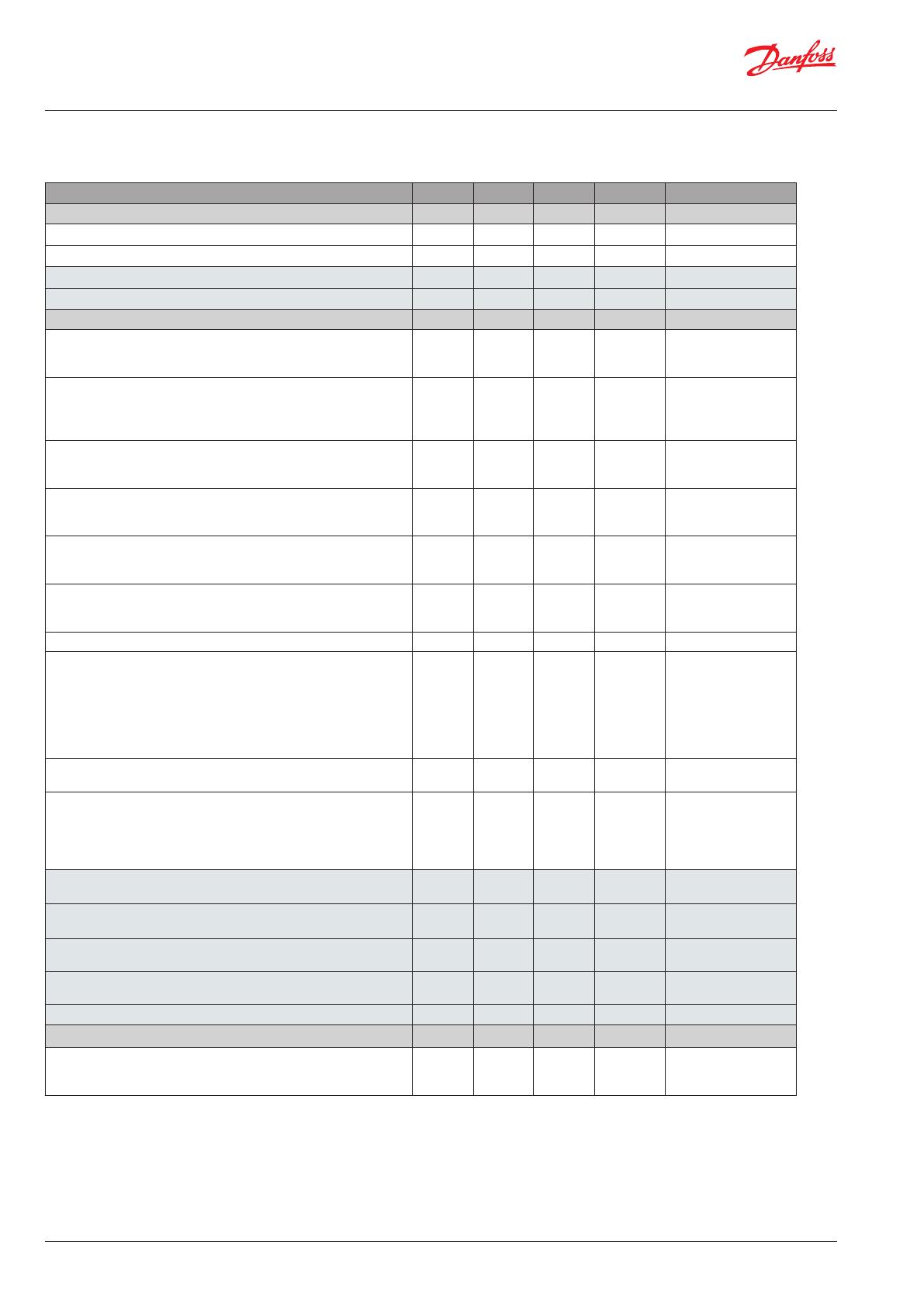
Modbus menu survey
Function Min Max Factory Unit AKM name
Gas level
Sensor 1 Actual gas level in % of range 0.0 100.0 - % Gas level %
Sensor 1 Actual gas level in ppm 0 FS
2
- ppm Gas level ppm
Sensor 2 Actual gas level in % of range 0.0 100.0 - % 2: Gas level %
Sensor 2 Actual gas level in ppm 0 FS
2
- ppm 2: Gas level ppm
Alarms Alarm settings
Indication of critical alarm (critical alarm of Gas1 or Gas2 active)
0: No active alarm(s)
1: Alarm(s) active
0 1 0 - GD alarm
Common indication of both critical and warning alarm as well as
internal and maintenance alarms
0: No active alarm(s), warning(s) or errors
1: Alarm(s) or warning(s)) active
0 1 0 - Common errors
Gas 1 Alarm limit in %.
Alarm limit in % (0-100), not lower 1: Warn Limit allowed
0.0 100.0 HFC: 25
CO2: 25
R290: 16
% Crit. limit %
Gas 1 Alarm limit in ppm
Alarm limit in ppm; 0: Warning Signal deactivated
0 FS
2
HFC: 500
CO2: 5000
R290: 800
ppm Crit. limit ppm
Gas 1. Warning limit in % (0-100) 0 100.0 HFC: 25
CO2: 25
R290: 16
% Warn. limit %
Gas 1
Warning limit ppm 0: Warning Signal deactivated
0.0 FS
2
HFC: 500
CO2: 5000
R290: 800
ppm Warn. limit ppm
High (critical and warning) alarm delay in seconds, if set to 0: no delay 0 600 0 sec Alarm delay s
When set to 1, the audible sounder are reset (and the relays if
defined: Relay rest enable) to no alarm indication. When the alarm is
reset or the time out duration is exceeded, the value is reset to 0.
Note: The alarm condition is not reset only the output indication is
reset.
0: Alarm outputs not reset
1: Alarm outputs reset –buzzer muted and relays reset if configured
0 1 0 - Reset alarm
Duration of alarm reset before automatic re-enable of alarm outputs.
A setting of 0 disables the ability to reset alarm.
0 9999 300 sec Reset alarm time
1
Relay reset enable:
Relay reset with alarm acknowledge function
1: (default) Relays wil be reset if the alarm acknowledge function is
activated
0: Relays remains active until the alarm condition clears
0 1 1 - Relay rst enable
1
Gas 2 Alarm limit in %.
Alarm limit in % (0-100), not lower 1: Warn Limit allowed
0.0 100.0 CO2: 25 % 2:Crit. limit %
Gas 2 Alarm limit in ppm
Alarm limit in ppm; 0: Warning Signal deactivated
0 FS
2
CO2: 5000 ppm 2:Crit. limit ppm
Gas 2. Warning limit in % (0-100) 0 100.0 CO2: 25 % 2:Warn. limit %
Gas 2. Warning limit ppm 0: Warning Signal deactivated 0.0 FS
2
CO2: 5000 ppm 2:Warn. limit ppm
High (critical and warning) alarm delay in seconds, if set to 0: no delay 0 600 0 sec 2:Alarm delay s
Service
Status of the sensors warm up period
0: Ready
1: Warming Up 1 or more sensors
0 1 0 - DGS Warm-up


