Page is loading ...

INSTRUCTION MANUAL
MASSIO CONTROLPADS AND KEYPADS
MCP-106, MCP-108, MKP-106, MKP-108

IMPORTANT SAFETY INSTRUCTIONS
COPYRIGHT NOTICE
AMX© 2015, all rights reserved. No part of this publication may be reproduced, stored in a retrieval system, or transmitted, in any form or by any
means, electronic, mechanical, photocopying, recording, or otherwise, without the prior written permission of AMX. Copyright protection claimed
extends to AMX hardware and software and includes all forms and matters copyrightable material and information now allowed by statutory or judicial
law or herein after granted, including without limitation, material generated from the software programs which are displayed on the screen such as
icons, screen display looks, etc. Reproduction or disassembly of embodied computer programs or algorithms is expressly prohibited.
LIABILITY NOTICE
No patent liability is assumed with respect to the use of information contained herein. While every precaution has been taken in the preparation of this
publication, AMX assumes no responsibility for error or omissions. No liability is assumed for damages resulting from the use of the information
contained herein. Further, this publication and features described herein are subject to change without notice.
AMX WARRANTY AND RETURN POLICY
The AMX Warranty and Return Policy and related documents can be viewed/downloaded at www.amx.com.
1. READ these instructions.
2. KEEP these instructions.
3. HEED all warnings.
4. FOLLOW all instructions.
5. DO NOT use this apparatus near water.
6. CLEAN ONLY with dry cloth.
7. DO NOT block any ventilation openings. Install in accordance with the manufacturer's instructions.
8. DO NOT install near any heat sources such as radiators, heat registers, stoves, or other apparatus (including amplifiers) that
produce heat.
9. DO NOT defeat the safety purpose of the polarized or grounding type plug. A polarized plug has two blades with one wider than the
other. A grounding type plug has two blades and a third grounding prong. The wider blade or the third prong are provided for your
safety. If the provided plug does not fit into your outlet, consult an electrician for replacement of the obsolete outlet.
10. PROTECT the power cord from being walked on or pinched, particularly at plugs, convenience receptacles, and the point where
they exit from the apparatus.
11. ONLY USE attachments/accessories specified by the manufacturer.
12. USE ONLY with a cart, stand, tripod, bracket, or table specified by the manufacturer, or sold with the apparatus. When a cart is
used, use caution when moving the cart/apparatus combination to avoid injury from tip-over.
13. UNPLUG this apparatus during lightning storms or when unused for long periods of time.
14. REFER all servicing to qualified service personnel. Servicing is required when the apparatus has been damaged in any way, such as
power-supply cord or plug is damaged, liquid has been spilled or objects have fallen into the apparatus, the apparatus has been
exposed to rain or moisture, does not operate normally, or has been dropped.
15. DO NOT expose this apparatus to dripping or splashing and ensure that no objects filled with liquids, such as vases, are placed on
the apparatus.
16. To completely disconnect this apparatus from the AC Mains, disconnect the power supply cord plug from the AC receptacle.
17. Where the mains plug or an appliance coupler is used as the disconnect device, the disconnect device shall remain readily operable.
18. DO NOT overload wall outlets or extension cords beyond their rated capacity as this can cause electric shock or fire.
The exclamation point, within an equilateral triangle, is intended to alert the user to the presence of important operating and maintenance
(servicing) instructions in the literature accompanying the product.
The lightning flash with arrowhead symbol within an equilateral triangle is intended to alert the user to the presence of uninsulated "dangerous
voltage" within the product's enclosure that may be of sufficient magnitude to constitute a risk of electrical shock to persons.
ESD Warning: The icon to the left indicates text regarding potential danger associated with the discharge of static electricity from an outside
source (such as human hands) into an integrated circuit, often resulting in damage to the circuit.
WARNING: To reduce the risk of fire or electrical shock, do not expose this apparatus to rain or moisture.
WARNING: No naked flame sources - such as candles - should be placed on the product.
WARNING: Equipment shall be connected to a MAINS socket outlet with a protective earthing connection.

3
Instruction Manual - Massio ControlPads and Keypads
ESD WARNING
WARNING: This product is intended to be operated ONLY from the voltages listed on the back panel or the recommended, or
included, power supply of the product. Operation from other voltages other than those indicated may cause irreversible
damage to the product and void the products warranty. The use of AC Plug Adapters is cautioned because it can allow the
product to be plugged into voltages in which the product was not designed to operate. If the product is equipped with a
detachable power cord, use only the type provided with your product or by your local distributor and/or retailer. If you are
unsure of the correct operational voltage, please contact your local distributor and/or retailer.
FCC AND CANADA EMC COMPLIANCE INFORMATION:
This device complies with part 15 of the FCC Rules. Operation is subject to the following two conditions:
(1) This device may not cause harmful interference, and (2) this device must accept any interference received, including
interference that may cause undesired operation.
NOTE: This equipment has been tested and found to comply with the limits for a Class B digital device, pursuant to part 15 of
the FCC Rules. These limits are designed to provide reasonable protection against harmful interference in a residential
installation. This equipment generates, uses and can radiate radio frequency energy and, if not installed and used in
accordance with the instructions, may cause harmful interference to radio communications. However, there is no guarantee
that interference will not occur in a particular installation. If this equipment does cause harmful interference to radio or
television reception, which can be determined by turning the equipment off and on, the user is encouraged to try to correct
the interference by one or more of the following measures:
•Reorient or relocate the receiving antenna.
•Increase the separation between the equipment and receiver.
•Connect the equipment into an outlet on a circuit different from that to which the receiver is connected.
•Consult the dealer or an experienced radio/TV technician for help.
Approved under the verification provision of FCC Part 15 as a Class B Digital Device.
Caution: Changes or modifications not expressly approved by the manufacturer could void the user's authority to operate this
device.
CAN ICES-3 (B)/NMB-3(B)
EU COMPLIANCE INFORMATION:
Eligible to bear the CE mark; Conforms to European Union Low Voltage Directive 2006/95/EC; European Union EMC Directive
2004/108/EC; European Union Restriction of Hazardous Substances Recast (RoHS2) Directive 2011/65/EU; European Union
WEEE (recast) Directive 2012/19/EU.
You may obtain a free copy of the Declaration of Conformity by visiting http://www.amx.com/techcenter/certifications.asp.
WEEE NOTICE:
To avoid ESD (Electrostatic Discharge) damage to sensitive components, make sure you are properly grounded before
touching any internal materials.
When working with any equipment manufactured with electronic devices, proper ESD grounding procedures must be
followed to make sure people, products, and tools are as free of static charges as possible. Grounding straps, conductive
smocks, and conductive work mats are specifically designed for this purpose. These items should not be manufactured
locally, since they are generally composed of highly resistive conductive materials to safely drain static discharges, without
increasing an electrocution risk in the event of an accident.
Anyone performing field maintenance on AMX equipment should use an appropriate ESD field service kit complete with at
least a dissipative work mat with a ground cord and a UL listed adjustable wrist strap with another ground cord
WARNING: Do Not Open! Risk of Electrical Shock. Voltages in this equipment are
hazardous to life. No user-serviceable parts inside. Refer all servicing to qualified
service personnel.
Place the equipment near a main power supply outlet and make sure that you can
easily access the power breaker switch.
This appliance is labeled in accordance with European Directive 2012/19/EU concerning waste of electrical and electronic
equipment (WEEE). This label indicates that this product should not be disposed of with household waste. It should be
deposited at an appropriate facility to enable recovery and recycling.

Table o f Con te nts
4
Instruction Manual - Massio ControlPads and Keypads
Table of Contents
Overview - Massio ControlPads .........................................................................7
Features .................................................................................................................................................. 7
Port Assignments by Massio ControlPad ............................................................................................... 7
Specifications .................................................................................................................... 8
MCP-106 ................................................................................................................................................. 8
MCP-108 ................................................................................................................................................. 9
Overview - Massio Keypads .............................................................................10
Specifications ................................................................................................................. 10
MKP-106 ............................................................................................................................................... 10
MKP-108 ............................................................................................................................................... 11
Wiring and Device Connections ......................................................................12
Overview ......................................................................................................................... 12
Control Ports and Indicators.......................................................................................... 13
RS-232 .................................................................................................................................................. 13
RELAYS .................................................................................................................................................. 13
I/O......................................................................................................................................................... 14
IR/Serial ............................................................................................................................................... 14
LAN (RJ-45)........................................................................................................................................... 15
Applying Power................................................................................................................................................... 15
ID Pushbutton....................................................................................................................................... 16
Installation ......................................................................................................18
Overview ......................................................................................................................... 18
Mounting Procedures ..................................................................................................... 18
Wallbox Mounting ................................................................................................................................. 18
Button Labeling ...............................................................................................20
Overview ......................................................................................................................... 20
Installing Acetate Button Labels.................................................................................... 20
Disassembling the Massio Device................................................................................... 21
Re-Assembling the Massio Device................................................................................... 22
Initial Configuration ........................................................................................23
Massio ControlPads......................................................................................................... 23
Before You Start.................................................................................................................................... 23
Obtaining the ControlPad’s IP Address................................................................................................ 23
Changing the ControlPad’s Network Address Information.................................................................. 24
Connecting to the ControlPad via USB ................................................................................................. 25
Toggling Between IP Addressing Modes: DHCP and Static IP ............................................................. 26
Configuration and Programming.......................................................................................................... 26
Programming...................................................................................................................................................... 26

Table o f Con te nts
5
Instruction Manual - Massio ControlPads and Keypads
WebConsole........................................................................................................................................................ 26
Accessing the WebConsole ................................................................................................................................ 26
Default User Names and Passwords................................................................................................................... 27
Massio Keypads.............................................................................................................. 27
Locating the IP Address of the Keypad ................................................................................................ 27
Toggling Between IP Addressing Modes: DHCP and Static IP ............................................................. 27
Upgrading Firmware .......................................................................................28
Overview .......................................................................................................................... 28
Massio ControlPads - Firmware Files ................................................................................................... 28
Master Firmware..................................................................................................................................................................... 28
Device Controller Firmware.................................................................................................................................................... 28
Before You Start .............................................................................................................. 28
Verifying the Current Firmware Version ......................................................................... 28
Downloading the Latest Firmware Files from www.amx.com ......................................... 29
NetLinx Controllers ............................................................................................................................... 29
Master and Device Firmware Kit Files for Massio ControlPads .......................................................................... 29
Downloading Massio ControlPad Firmware Files on www.amx.com.................................................................. 29
Required Order of Firmware Updates ............................................................................. 29
Upgrading Firmware via NetLinx Studio ........................................................................ 30
Resetting the Factory Default System and Device Values............................................... 32
Programming ..................................................................................................33
Programming the Massio ControlPads and Keypads...................................................... 33
Button Layouts...................................................................................................................................... 33
Channels ............................................................................................................................................... 33
Port Assignments by Massio ControlPad ............................................................................................. 33
Port Numbers and Levels (ControlPads) .............................................................................................. 34
Port Numbers and Levels (Keypads) .................................................................................................... 34
Programming the Knob and LED Bargraph (MCP/MKP-108)............................................................... 34
Knob - Button 11................................................................................................................................... 34
Knob - Buttons 12-13 ........................................................................................................................... 34
Navigation Wheel - Level Control ......................................................................................................... 34
Display Bargraph .................................................................................................................................. 34
Supported SEND_LEVELs ...................................................................................................................... 34
SEND_LEVEL........................................................................................................................................................................... 34
Supported SEND_COMMANDs............................................................................................................... 35
@BRT ...................................................................................................................................................................................... 35
BMODE .................................................................................................................................................................................... 35
?EXPANSION........................................................................................................................................................................... 35
LED-DIS................................................................................................................................................................................... 35
Terminal (Telnet) Commands ......................................................................................... 36
Establishing a Terminal Connection via Telnet .................................................................................... 36
LED-EN .................................................................................................................................................................................... 36
REBOOT................................................................................................................................................................................... 36
SET_NDX_DESC....................................................................................................................................................................... 36
Telnet User Name and Password.......................................................................................................... 37

Table o f Con te nts
6
Instruction Manual - Massio ControlPads and Keypads
Additional Notes ................................................................................................................................... 37
Setting a Telnet User Name and Password .......................................................................................... 37
Telnet Commands ........................................................................................................... 38
? or Help.................................................................................................................................................................................. 38
DEVICE STATUS ...................................................................................................................................................................... 38
EXIT ........................................................................................................................................................................................ 38
FACTORYFWIMAGE................................................................................................................................................................. 38
GET CONFIG............................................................................................................................................................................ 38
GET CONNECTION................................................................................................................................................................... 38
GET DEVICE............................................................................................................................................................................. 38
GET DNS .................................................................................................................................................................................. 39
GET ETHERNET MODE ............................................................................................................................................................. 39
GET FRIENDLY <name>.......................................................................................................................................................... 39
GET IP ..................................................................................................................................................................................... 39
GET LOCATION........................................................................................................................................................................ 39
GET SN .................................................................................................................................................................................... 39
INFO........................................................................................................................................................................................ 39
MSG [ON|OFF] ......................................................................................................................................................................... 39
NDP UNBIND ........................................................................................................................................................................... 39
PING [ADDRESS]..................................................................................................................................................................... 39
REBOOT................................................................................................................................................................................... 39
RENEW DHCP ......................................................................................................................................................................... 40
RESET FACTORY..................................................................................................................................................................... 40
SET CONNECTION .................................................................................................................................................................. 40
SET DEVICE ............................................................................................................................................................................ 40
SET DNS ................................................................................................................................................................................. 40
SET ETHERNET MODE............................................................................................................................................................. 40
SET FRIENDLY ........................................................................................................................................................................ 41
SET IP .................................................................................................................................................................................... 41
SET LOCATION ....................................................................................................................................................................... 41
SET TELNET PORT .................................................................................................................................................................. 41
SET TELNET USERNAME......................................................................................................................................................... 41
SET TELNET PASSWORD ........................................................................................................................................................ 41
SHOW CONNECTION LOG....................................................................................................................................................... 41
Notes on Specific Telnet Clients..................................................................................... 42
Windows Client Programs .................................................................................................................... 42
Linux Telnet Client ................................................................................................................................ 42
Enabling/Disabling Telnet on the Keypad...................................................................... 42
SHOW CONNECTION STATS................................................................................................................................................... 42
SHOW LOG.............................................................................................................................................................................. 42

Overview - Massio ControlPads
7
Instruction Manual - Massio ControlPads and Keypads
Overview - Massio ControlPads
The Massio MCP-106 (FG2102-06) and MCP-108 (FG2102-08) ControlPads each feature built-in Ethernet ports and combine a
controller with a 6- or 8-button keypad. The 6-Button Massio ControlPad mounts into a standard 1 gang US, UK, or EU back box.
The 8-Button Massio ControlPad mounts into a standard 2 gang US, UK, or EU back box.
FIG. 1 displays the Massio ControlPads.
FIG. 1
Massio ControlPads
Features
All-in-one Keypad/Controller – Combines a user interface with an on-board controller
Includes AMX Control – Controls all the same devices as NetLinx Integrated Controllers, with the same capabilities and
macro functions
Simple to Program with RPM – Uses AMX’s Rapid Project Maker (RPM) software to quickly configure and program a system
Simple Integration with RMS – Using RPM, easily integrate AMX’s Resource Management Suite (RMS) with a Massio
ControlPad to provide a platform for real-time performance monitoring and maintenance
Display Monitoring – Use the ControlPad with RMS to monitor power status, input status, lamp hours and filter hours
Web-based Control – Remotely login to ControlPads and execute button presses
Inactivity Timer – Turn off equipment after lack of activity (timeouts) to save energy
Built In Control Ports – Serial and IR ports available to communicate and control common presentation equipment
Backlit Buttons – Can flash or turn on/off when pressed
Execute Multiple Functions at Once – Macros can be written to trigger multiple functions through a single button press
Works with AMX IR Files – Leverage thousands of pre-existing AMX IR files on AMX.com
Standard Enclosures – Standard back box mounting options for US, UK and EU
Native Direct Connection to RMS – No proxy required
Master-to-Master Communication – The ControlPads support AMX Master-to-Master communication when paired with
another AMX Master
Port Assignments by Massio ControlPad
The following table lists the port assignments for Massio ControlPads:
Port Assignments By ControlPad
ControlPad RS-232 IR/Serial Relays I/O Keypad
MCP-106 Port 1 Port 11 N/A N/A Port 28
MCP-108 Ports 1-2 Ports 11-12 Port 21 Port 22 Port 28
MCP-108
MCP-106 (Landscape)

Overview - Massio ControlPads
8
Instruction Manual - Massio ControlPads and Keypads
Specif ications
The following sections list the specifications for the Massio ControlPads.
MCP-106
The following table lists the specifications for the MCP-106:
MCP-106 Specifications
Ge n e r a l :
Dimensions (HWD): Portrait: 4 11/16" x 3 7/16" x 9/16" (119 mm x 87.5 mm x 13.9 mm)
Landscape: 3 7/16" x 4 11/16" x 9/16" (87.5 mm x 119 mm x 13.9 mm)
Mount onto standard 1 gang US, UK, or EU back boxes
Weight: Approximately 0.25 lb (0.11 kg)
Front Panel Components: 6 buttons
Colors/Styles Available: • Portrait, Black: MCP-106P-BL (FG2102-06P-BL)
• Portrait, White: MCP-106P-WH (FG2102-06P-W)
• Landscape, Black: MCP-106L-BL (FG2102-06L-BL)
• Landscape, White: MCP-106L-WH (FG2102-06L-W)
Active Power Requirements:
Voltage, DC (Typical): PoE (37V-57V)
Voltage DC Range: 37V-57V per 802.3af specification
Power Connector: (1) RJ-45 Ethernet
Maximum Power Draw: 4.5W
Power Supply:
External, Required: Any POE injector or switch, conforming to the 802.3af standard including AMX’s PS-POE-AF-TC (FG423-83),
not included
Environmental:
Temperature (Operating): 32º F to 104º F (0º C to 40º C)
Temperature (Storage): 14º F to 140º F (-10º C to 60º C)
Humidity (Operating): 5% to 85% RH
Ethernet:
Ethernet Connection: (1) 10/100; Port provides TCP/IP communication. This is an Auto MDI/MDI-X enabled port, which allows you
to use either straight-through or crossover Ethernet cables. The Ethernet Port LEDs show communication
activity, connection status, speeds, and mode information.
Control Ports and Indicators:
RS-232 Port: (1) 3-position 3.5mm Screw Terminal; 300 - 115,200 baud
IR/Serial Port: (1) 2-position 3.5mm Screw Terminal; IR Transmit / 1-way Serial ports
Support high-frequency carriers up to 1.142 MHz
Program Port: (1) USB Mini-B, USB
ID Pushbutton Reset factory settings, reset factory image, toggle between DHCP or static IP addressing mode
Memory:
Flash: 4 GB
Memory Card: 4 GB SD
DDRAM: 256 MB
Certifications: • FCC Class B
• CE EN 55022
•EN 55024
• IEC/EN-60950-1
•UL 60950-1

Overview - Massio ControlPads
9
Instruction Manual - Massio ControlPads and Keypads
MCP-108
The following table lists the specifications for the MCP-108:
MCP-108 Specifications
Ge n e r a l :
Dimensions (HWD): 4 11/16" x 6" x 1" (119 mm x 152.5 mm x 26 mm)
Weight: Approximately 0.41 lb (0.19 kg)
Mounting Options: Mount onto standard 2 gang US, UK, or EU back boxes
Front Panel Components: • 8 Buttons
• 1 Volume Knob with Push Mute
• 7 LED Bar Graph Indicator
Colors Available: • Black: MCP-108-BL (FG2102-08-BL)
• White: MCP-108-WH (FG2102-08-W)
Active Power Requirements:
Voltage, DC (Typical): PoE (37V-57V)
Voltage DC Range: 37V-57V per 802.3af specification
Power Connector: (1) RJ-45 Ethernet
Maximum Power Draw: 5.0W, plus any power used by the I/O port, which can draw up to an additional 6.0W.
Power Supply:
External, Required: Any POE injector or switch, conforming to the 802.3af standard including AMX’s PS-POE-AF-TC (FG423-83),
not included
Environmental:
Temperature (Operating): 32º F to 104º F (0º C to 40º C)
Temperature (Storage): 14º F to 140º F (-10º C to 60º C)
Humidity (Operating): 5% to 85% RH
Ethernet:
Ethernet Connection: (1) 10/100; Port provides TCP/IP communication. This is an Auto MDI/MDI-X enabled port, which allows
you to use either straight-through or crossover Ethernet cables. The Ethernet Port LEDs show
communication activity, connection status, speeds, and mode information.
Control Ports and Indicators:
RS-232 Port: (2) 3-position 3.5mm Screw Terminals; 300 - 115,200 baud
IR/Serial Port: (2) 2-position 3.5mm Screw Terminals; IR Transmit / 1-way Serial ports
Support high-frequency carriers up to 1.142 MHz
I/O Channels: (1) 4-position 3.5 mm Screw Terminal; 2-channel binary I/O port for contact closure with each input being
capable of voltage sensing
Relay Connection: (1) 4-position 3.5mm Screw Terminal; (2) single-pole, single-throw relays
Each relay can switch up to 24 V
DC
or 28 V
AC
@ 1 A
Each relay is independently controlled
Program Port: (1) USB Mini-B, USB
ID Pushbutton Reset factory settings, reset factory image, toggle between DHCP or static IP addressing mode
Memory:
Flash: 4 GB
Memory Card: 4 GB SD
DDRAM: 256 MB
Certifications: • FCC Class B
• CE EN 55022
•EN 55024
•IEC/EN-60950-1
• UL 60950-1

Overview - Massio Keypads
10
Instruction Manual - Massio ControlPads and Keypads
Overview - Massio Keypads
The Massio MKP-106 (FG5793-06) and MKP-108 (FG5793-08) Keypads are keypad-only versions of the Massio ControlPad. The
keypads can serve as second user interfaces or as primary UI in spaces that already contain a separate controller. Massio Keypads
connect to a controller via Ethernet. The 6-Button Massio Keypad mounts into a standard 1 gang US, UK, or EU back box. The
8-Button Massio Keypad mounts into a standard 2 gang US, UK, or EU back box.
FIG. 2 displays the Massio ControlPads.
FIG. 2
Massio Keypads
Specif ications
The following sections list the specifications for the Massio Keypads.
MKP-106
The following table lists the specifications for the MKP-106:
MKP-106 Specif ications
Ge n e r a l :
Dimensions (HWD): Portrait: 4 11/16" x 3 7/16" x 9/16" (119 mm x 87.5 mm x 13.9 mm)
Landscape: 3 7/16" x 4 11/16" x 9/16" (87.5 mm x 119 mm x 13.9 mm)
Mount onto standard 1 gang US, UK, or EU back boxes
Weight: Approximately 0.25 lb (0.11 kg)
Front Panel Components: 6 buttons
ID Pushbutton Reset factory settings, reset factory image, toggle between DHCP or static IP addressing mode
Colors/Styles Available: • Portrait, Black: MKP-106P-BL (FG5793-06P-BL)
• Portrait, White: MKP-106P-WH (FG5793-06P-W)
• Landscape, Black: MKP-106L-BL (FG5793-06L-BL)
• Landscape, White: MKP-106L-WH (FG5793-06L-W)
Active Power Requirements:
Voltage, DC (Typical): PoE (37V-57V)
Voltage DC Range: 37V-57V per 802.3af specification
Power Connector: (1) RJ-45 Ethernet
Regulatory Compliance: • FCC CFR Title 47 Part 15
• CE EN 55022
• CE EN 55024
• CE EN 60950-1
• IEC-60950-1
•UL 60950-1
•C-Tick CISPR 22
• IC CISPR 22
• VCCI CISPR 22
•RoHS
•WEEE
Power Supply:
External, Required: Any POE injector or switch, conforming to the 802.3af standard including AMX’s PS-POE-AF-TC (FG423-83),
not included.
MKP-108
MKP-106 (Landscape)

Overview - Massio Keypads
11
Instruction Manual - Massio ControlPads and Keypads
MKP-108
The following table lists the specifications for the MKP-108:
MKP-106 Specif ications (Cont.)
Environmental:
Temperature (Operating): 32º F to 122º F (0º C to 50º C)
Temperature (Storage): 14º F to 140º F (-10º C to 60º C)
Humidity (Operating): 5% to 85% RH
Ethernet:
Ethernet Connection: (1) 10/100; Port provides TCP/IP communication. This is an Auto MDI/MDI-X enabled port, which allows you
to use either straight-through or crossover Ethernet cables. The Ethernet Port LEDs show communication
activity, connection status, speeds, and mode information.
Memory:
Flash: 4 GB
Memory Card: 4 GB SD
DDRAM: 256 MB
MKP-108 Specif ications
Ge n e r a l :
Dimensions (HWD): 4 11/16" x 6" x 1" (119 mm x 152.5 mm x 26 mm)
Weight: Approximately 0.41 lb (0.19 kg)
Mounting Options: Mount onto standard 2 gang US, UK, or EU back boxes
Front Panel Components: • 8 Buttons
• 1 Volume Knob with Push Mute
• 7 LED Bar Graph Indicator
ID Pushbutton Reset factory settings, reset factory image, toggle between DHCP or static IP addressing mode
Colors Available: • Black: MKP-108L-BL (FG5793-08L-BL)
• White: MKP-108L-WH (FG5793-08L-W)
Active Power Requirements:
Voltage, DC (Typical): PoE (37V-57V)
Voltage DC Range: 37V-57V per 802.3af specification
Power Connector: (1) RJ-45 Ethernet
Regulatory Compliance: • FCC CFR Title 47 Part 15
• CE EN 55022
• CE EN 55024
• CE EN 60950-1
• IEC-60950-1
•UL 60950-1
•C-Tick CISPR 22
•IC CISPR 22
•VCCI CISPR 22
•RoHS
• WEEE
Power Supply:
External, Required: Any POE injector or switch, conforming to the 802.3af standard including AMX’s PS-POE-AF-TC (FG423-83),
not included
Environmental:
Temperature (Operating): 32º F to 122º F (0º C to 50º C)
Temperature (Storage): 14º F to 140º F (-10º C to 60º C)
Humidity (Operating): 5% to 85% RH
Ethernet:
Ethernet Connection: (1) 10/100; Port provides TCP/IP communication. This is an Auto MDI/MDI-X enabled port, which allows you
to use either straight-through or crossover Ethernet cables. The Ethernet Port LEDs show communication
activity, connection status, speeds, and mode information.
Memory:
Flash: 4 GB
Memory Card: 4 GB SD
DDRAM: 256 MB

Wiring and Device Connections
12
Instruction Manual - Massio ControlPads and Keypads
Wiring and Device Connections
Overview
This section describes the device connectors and ports available on each type of Massio ControlPad. Here you can find wiring and
electrical capacities for each type of connector.
FIG. 3 displays the rear panel of the MCP-106.
FIG. 3
MCP-106 rear panel
FIG. 4 displays the rear panel of the MCP-108.
FIG. 4
MCP-108 rear panel
Ethernet port
Program port
RS-232 port
IR/Serial port
RS-232 ports
Ethernet port
Program port
IR/Serial ports
I/O port
Relay ports

Wiring and Device Connections
13
Instruction Manual - Massio ControlPads and Keypads
Control Ports and Indicators
The following sub-sections describe each control port on the Massio ControlPads. Refer to Overview section on page 12 for the
component layout of the rear panels of each type of Massio ControlPad.
RS-232
The Massio ControlPads features up to two RS-232 300-115,200 baud connector ports so you can connect up to two serial devices
to the ControlPad. The MCP-106 features one RS-232 connector; the MCP-108 features two connectors. The serial connectors
comply with EIA-232-F signal levels. The RX line supports polling for RS-232 devices for statuses such as power status, input
status, and lamp hours, so that this information can be provided to RMS.
NOTE: Massio ControlPads do not support RS-422 or RS-485 communications to devices.
FIG. 5 displays the RS-232 ports on the MCP-108.
FIG. 5
RS-232 Serial Ports (MCP-108)
FIG. 6 displays the wiring for the RS-232 connector.
FIG. 6
RS-232 connector wiring
RELAYS
You can connect up to two independent external relay devices to the Relay connectors on the ControlPad. The relay port is only
available on the MCP-108.
FIG. 7 displays the RELAYS connector.
FIG. 7
RELAYS connector
Each relay is isolated and normally open.
24 V
DC
@ 1 A maximum
28 V
AC
@ 1 A maximum
RX
ControlPad
TX
GNDGND
RX
TX
External Device

Wiring and Device Connections
14
Instruction Manual - Massio ControlPads and Keypads
I/O
The I/O port (available only on the MCP-108) responds to switch closures and voltage level (high/low) changes, or can be used for
logic-level outputs. The +12 pin provides +12 V
DC
@ 200 mA and is designed as a power output for the PCS Power Current
Sensors, VSS2 Video Sync Sensors (or equivalent). The GND connector is a common ground and is shared by all I/O ports. A
common ground is shared with I/O ports 1 - 2.
FIG. 8 displays the I/O connector.
FIG. 8
I/O port
CAUTION:
Improper wiring could damage your ControlPad. The CP-3008 ControlPad has the ground and power signals in swapped
positions on the I/O port. If you are replacing a CP-3008 ControlPad with the MCP-108, you may need to make a wiring change in
your I/O connector to avoid damaging the MCP-108.
A contact closure between the GND and an I/O port is detected as a Push.
When used for voltage inputs, the I/O port detects a low signal (0 - 1.5 V
DC
) as a Push, and a high signal
(3.5 - 5 V
DC
) as a Release. (This I/O port uses 5V logic but can handle up to 12V without harm.)
The following table provides wiring requirements for the I/O port:
IR/Serial
You can connect up to two IR-controllable devices to the IR connectors to the Massio ControlPads. The MCP-106 features only one
IR connector; the MCP-108 features two connectors.
The IR connectors support generating carriers up to 1.142 MHz. The IR connectors accept an IR Emitter (CC-NIRC) that mounts
onto the device's IR window, or a mini-plug (CC-NSER) that connects to the device's control jack.
You can also connect a data (0 - 5 V
DC
) device.
FIG. 9 displays the IR/SERIAL connector.
FIG. 9
IR/SERIAL connector
The IR/Serial connector wiring specifications are listed in the following table.
IMPORTANT: The IR positive (+) and negative (-) connections are positioned from left to right. The signal connector is located on the
left side of the IR connection while the ground connector is located on the right side.
I/O Port Wiring Specif ications
Signal Function
GND: Signal GND
1: Output
2: Output
+12 V: PWR
IR Connector Wiring Specif ications (per Port)
IR connections Signal Function
1Signal 1 (+)
GND (-)
IR data
Signal GND
2 (MCP-108 only) Signal 2 (+)
GND (-)
IR data
Signal GND
CAUTION:
Do NOT connect a power connector to either IR port. Doing so may damage the ControlPad.
+ - + -

Wiring and Device Connections
15
Instruction Manual - Massio ControlPads and Keypads
LAN (RJ-45)
The LAN RJ-45 port provides 10/100 Mbps communication via Cat5/5e/6 network cable. The LAN port automatically negotiates
the connection speed (10 Mbps or 100 Mbps), and whether to use half duplex or full duplex mode. The LAN port is best used for
connecting to a network switch. This is an Auto MDI/MDI-X enabled port, which allows you to use either straight-through or
crossover Ethernet cables. The port LEDs show communication activity, connection status, speeds, and mode information.
The LAN port also receives its power via the LAN port and Power-over-Ethernet (PoE) when you connect this port to a PoE switch
which conforms to the 802.3af standard. See the Applying Power section on page 15 for information on PoE setup.
FIG. 10 displays the LAN port.
FIG. 10
LAN port
FIG. 11 provides the pinouts and signals for the LAN connector and cable.
FIG. 11
RJ-45 wiring diagram
NOTE: If Ethernet connectivity is lost on any ControlPad, and then re-established, connectivity may take some time to resume. You
will be unable to program the ControlPad until it is fully online.
Applying Power
Applying power to Massio ControlPads and Keypads requires Cat5 cable and a PoE injector, such as the PS-POE-AF-TC (FG423-83)
available from AMX, or a PoE-capable Ethernet switch which conforms to the 802.3af standard. The network must be connected
through the PoE injector to send power to the ControlPad.
1. Connect the PoE injector to an AC outlet (~100-240V) using a standard power cord.
2. Connect the switch category cable to the Data In port on the PoE injector (FIG. 12).
FIG. 12
Connecting to a PoE Injector
3. Using a separate category cable, connect the Data & Power Out port on the PoE injector to LAN Port on the ControlPad or
keypad.
Data & Power
Out
Data In
Category cable to ControlPad
Cat5 cable from
the network
or Keypad

Wiring and Device Connections
16
Instruction Manual - Massio ControlPads and Keypads
ID Pushbutton
Each Massio ControlPad and Keypad features a pinhole reset pushbutton located on the bottom of the device.
FIG. 13 displays the location of the reset pushbutton on each ControlPad or keypad.
FIG. 13
Location of the ID Pushbuttons on each ControlPad
You can use the ID pushbutton to perform the following procedures:
Perform a factory reset of the ControlPad or Keypad: Press the ID pushbutton for approximately 10 seconds during the
boot process. While pressing the ID pushbutton, disconnect and reconnect the cable from the LAN port on the rear panel
of the ControlPad to reset the ControlPad’s factory defaults. During factory reset, the backlight turns off for all buttons,
but all buttons should be back online after 1-2 minutes. If you do not hold in the ID pushbutton for the full 10 seconds,
the reset does not occur. (There is no soft reboot with the ID pushbutton, but you can perform a soft reboot from the
web pages.)
On Massio ControlPads and Keypads, the LEDs on buttons 1 and 2 blink while you keep them pressed. Hold them until the
LEDs begin blinking at double the rate (approximately10 seconds.) Release the buttons and the keypad will reset.
NOTE: When you reset a ControlPad or Keypad, the device is restored to the factory default, so you will lose any scripts, IRL f iles,
Device Interrogation settings, or RMS server information loaded on the system.
Restore the factory image on the ControlPad or Keypad: Press the ID pushbutton for approximately 20 seconds or longer
during the boot process. While pressing the ID pushbutton, disconnect and reconnect the cable from the LAN port on the
rear panel of the device to restore the factory image firmware on the ControlPad.
Toggle between a DHCP or static IP address. See the Toggling Between IP Addressing Modes: DHCP and Static IP section on
page 26 for more information.
In place of using the ID pushbutton, you can press buttons 1 and 2 simultaneously on the ControlPad or keypad to simulate the
functions of the ID pushbutton. You must keep both buttons pressed for approximately 10 or 20 seconds as you would with the ID
pushbutton to perform a factory reset or restore the factory firmware image on the device. You must also disconnect and
reconnect the cable from the LAN port while pressing the buttons. FIG. 14 displays the locations of buttons 1 and 2 on each Massio
device.
FIG. 14
Button layout for Massio ControlPads and Keypads
NOTE: RPM applies a different numbering scheme in its background for the ControlPads. Disregard any button pushes you see in
NetLinx Studio.
6-button
ID pushbutton
8-button
6-button (portrait)
8-button
1
2
1
2
3
4
56
34
5
6
7
8
11
13
12
Rotate counter-clockwise
= Button #13
Rotate clockwise
= Button #12

Wiring and Device Connections
17
Instruction Manual - Massio ControlPads and Keypads
The button assignments are the same on the portrait and landscape versions of the MCP-106 and MKP-106. On a landscape
installation, button 1 is in the lower left corner of the device (see FIG. 15).
FIG. 15
Button layout (6-button landscape)
You can also simultaneously press buttons 4, 5, and 6 to power cycle the device. Press all three buttons simultaneously and hold
them for 20 seconds to power cycle the device (see FIG. 16).
FIG. 16
Press buttons marked with X to power cycle the device
On a landscape installation, consult FIG. 17 for the locations of the button to press for a power cycle.
FIG. 17
Press buttons marked with X to power cycle the device
6-button (landscape)
6
4
2
5
3
1
6-button (portrait)
8-button
X
X
X
X
X
X
6-button (landscape)
X
X
X

Installation
18
Instruction Manual - Massio ControlPads and Keypads
Installation
Overview
This chapter describes installing Massio ControlPads and Keypads. The MCP-106 and MKP-106 mount onto standard 1 gang US,
UK, or EU back boxes. The MCP-108 and MKP-108 mount onto standard 2 gang US, UK, or EU back boxes.
NOTE: Before touching the device, discharge the static electricity from your body by touching a grounded metal object.
NOTE: It is best to install button labels before mounting the device. Doing so keeps you from disassembling the ControlPad after
mounting it. For instructions on installing button labels, see the Button Labeling section on page 20.
Mounting Procedures
AMX recommends mounting each type of ControlPad or Keypad in standard a conduit box per NEC specs section 370. You can
mount the MCP-108 and MKP-108 to a podium using the provided metal mounting bracket.
NOTE: Before installing and mounting the device, you should test it to see that it can receive power. See the Applying Power section
on page 15 for more information.
Wallbox Mounting
Perform these steps to mount the device into a back box:
1. Install the back box into the surface of the desired location for the device. Be sure to thread any appropriate wiring through
the back box.
IMPORTANT: Leave 3/8" (9.52mm) of space between the top of the mounting bracket and any overhanging or otherwise obstructing
surface. The extra space is required for attaching the device frame to the mounting bracket.
2. Once the back box is installed and secured, secure the metal mounting bracket to the back box using the provided screws.
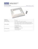
FIG. 18 displays the location of the screw holes for the metal mounting brackets for each type of Massio device.
FIG. 18
Location of screw holes on metal mounting brackets.
3. Peel the plastic covering off of the insulator on the rear panel of the device. You can discard the plastic covering after removing
it.
4. Make all necessary connections to the ports on the rear panel of the ControlPad. Be sure to connect category cable to the LAN
port to supply power to the device. See the Applying Power section on page 15 for more information.
5. Attach the device frame to the mounting bracket by hooking the top of the device frame onto the extended lip at the top of the
mounting bracket.
MCP-106
MCP-108

Installation
19
Instruction Manual - Massio ControlPads and Keypads
FIG. 19 illustrates how to connect the device frame to the mounting bracket.
FIG. 19
Attaching the frame to the mounting bracket (MCP-106 displayed)
6. Press the sides of the device frame to snap them into place.
7. Press the bottom corners of the device frame to snap them into place. The metal clip on the mounting bracket should align
with the open spaces located at the bottom of the device frame. The clip should fit inside this space and lock the device frame
into position on the mounting bracket. There are two metal clips on the 8-button Massio devices. There is only one on the
6-button devices.
FIG. 20 displays the location of the metal clip on the 6-button devices.
FIG. 20
Metal clip from mounting bracket locking device frame onto bracket
FIG. 21 displays the locations of the metal clips on the 8-button devices.
FIG. 21
Metal clips from mounting bracket locking device frame onto bracket
8. Connect the faceplate to the device frame by snapping the top corners of the faceplate into place on the device frame. If
connected properly, the faceplate should hold itself in place against the device frame.
NOTE: If you need to label the buttons on the device or replace any key caps, it is best to do so before attaching the faceplate. Consult
the Button Labeling section on page 20 for instructions.
9. Press the bottom corners of the faceplate until each corner snaps into place with the device frame.
Hook top of frame onto the lip
of the mounting bracket
Metal clip from mounting bracket
Metal clips from mounting bracket

Button Labeling
20
Instruction Manual - Massio ControlPads and Keypads
Button Labeling
Overview
Massio ControlPads and Keypads come with a set of clear plastic Button Caps which are designed to fit tightly over the
pushbuttons, and allow you to place a label on each button according to the requirements of your particular installation.
Massio devices also come with a pre-printed acetate sheet with a range of 70 (pre-cut) button label inserts. The button labels
provided will accommodate most installations, but it is also possible to print your own button labels on acetate for custom button
labeling.
FIG. 22
Acetate sheet of 70 standard button labels (pre-cut)
Installing Acetate Button Labels
Follow these instructions to install the acetate button labels and Button Caps:
1. Remove the faceplate from the device.
2. Remove the cone and diffuser from the button. The cone and diffuser are adhered together and should not be separated.
3. Peel off the desired Button Label from the included acetate sheet. If you have printed your own custom button labels on
acetate, cut each button label to fit inside the Button Caps.
Custom button labels must be cut to a 14mm (0.55") square to fit securely inside the Button Caps.
The thickness of the acetate used must not exceed .004” (0.10 mm).
4. Place the Button Cap face-down, and insert the Button Label into the bottom of the Button Cap (FIG. 23).
Orient the Button Label inside the Button Cap so that the two clips are located on the top and bottom sides of the readable
text on the Button Label, as indicated in FIG. 23.
Be sure to place the Button Label face-down inside the Button Cap, otherwise the label will be seen in reverse.
/