Hydrologic EVOLUTION-RO1000 Operating instructions
- Category
- Water dispensers
- Type
- Operating instructions

Installation & Maintenance Manual

NOTES:
___________________________________________
___________________________________________
___________________________________________
___________________________________________
___________________________________________
___________________________________________
___________________________________________
___________________________________________
___________________________________________
___________________________________________
___________________________________________
___________________________________________
___________________________________________
___________________________________________
___________________________________________
___________________________________________
___________________________________________
___________________________________________
___________________________________________
___________________________________________
___________________________________________
___________________________________________
1

EVOLUTION-RO1000 Reverse Osmosis System
Installation and Maintenance Manual
SAFETY GUIDES
Read and follow all steps and guides carefully before installing and
using your reverse osmosis system. The included Quick Start Guide is
only a basic guide to help you through the initial setup of the system.
Please read this more detailed manual before running the system.
Do not use this product to make safe drinking water from non-potable
water sources. Do not use the system on microbiologically unsafe
water, or water of unknown quality without adequate disinfection
before or after the system.
This reverse osmosis system contains replaceable components
(membrane elements). These components are critical for the
effective reduction of total dissolved solids and specific
contaminants.
The Reverse Osmosis System does not have a monitoring device for
contaminants. To verify that the system is performing satisfactorily
the product water should be tested periodically by the system’s
installing dealer or a certified laboratory, every six months. The
laboratory should be certified for testing the specific contaminants of
concern. For a listing of certified laboratories, contact local regulatory
agencies or Hydro-Logic. Within the United States, many state-run
Department of Natural Resources or Department of Health Services
maintain listings of certified laboratories.
The optional TDS Monitor can be used to monitor incoming tap water
and outgoing purified water PPM (Parts Per Million) of TDS (total
dissolved solids).
Consult your local public works department for plumbing and
sanitation codes. Follow your local codes if they differ from this
manual.
The reverse osmosis system works on water pressures of 40 psi
(2.8 bar) minimum to 80 psi (5.5 bar) maximum. Water pressure can
be reduced by installing a pressure reducing valve in the water
supply pipe to the RO system. A booster pump should be used for low
pressure applications. Both are available through your dealer
or Hydro-Logic.
Do not install the reverse osmosis system in extreme hot or cold
temperatures. Temperature of the water supply to the reverse
osmosis system must be between 40°F (4°C) and 100°F (38°C).
Do not install on hot water lines.
The reverse osmosis membranes contain a foodgrade preservative
for storage and shipment. All new membranes require a minimum 2
hour rinse to properly rinse out the preservative. The preservative
is not harmful but makes the product water taste objectionable.
Rinsing the membrane also acts as a performance conditioner. All
new membranes will reach their stable maximum performance after 8
hours of rinsing.
THE BASIC REVERSE OSMOSIS SYSTEM
Your Reverse Osmosis System is a water treatment unit. It uses water
pressure to reverse a natural physical process called osmosis. Water,
under pressure, is forced through a semi-permeable membrane to
filter out minerals and impurities. Treated drinking water goes through
the blue line. Minerals and impurities are sent to the drain with RO
waste water through the black line.
The system includes a replaceable carbon pre-filter and 2 membrane
elements. The pre-filter reduces sand, silt, dirt, rust particles, other
sediments, chlorine, chloramines, iron and sulfur from the incoming
water supply before they enter the RO membrane elements. An
optional high capacity pre-filter, the Pre-Evolution, is available to
add 2 extra stages of pre-filtration. This will help further reduce the
contaminants listed above as well as cut down on filter changes and
maintenance of the Evolution-RO1000. An optional De-Ionization
post-filter will remove any remaining PPM of TDS in the water after
passing through the RO system.
BEFORE INSTALLING THE RO SYSTEM
Best performance of the system will be achieved when the •
incoming water has been pre-treated.
The water coming into the system must be within certain limits •
for sediments, pressure, etc. Refer to the specifications to
determine if your installation is within the limits.
A water quality analysis can be performed to determine if •
incoming water requires any treatment. Contact your dealer/
installer or Hydro-Logic.
The filters and membrane elements in the RO system need •
to be replaced on a regular basis. Follow the instructions for
replacement that are in this manual.
NOTE: For optimal system performance, use the system for at least 2
minutes continuously each day.
WARNING:
The RO system is designed to work without the
aid of a pressurized storage tank. Installation of
a pressurized storage tank will negatively affect
system performance. You can, however, store the
purified water in non-pressurized storage tank or
reservoir. Using the optional 3/8” Float Valve will
ensure you do not flood your working area.
NOTE: High levels of certain contaminantsin
the incoming water may prematurely foul the
membranes and/or the pre-filter. A water softener
or other forms of pre-filtration may be necessary.
Contact Hydro-Logic for options.
2

THE BASIC REVERSE OSMOSIS SYSTEM cont.
COMPLETE
MANIFOLD
PN 23062 (1 pc)
SUPPORT
LEG/SUMP
WRENCH
PN 23063
(1 pc)
SUMP
(FILTER
HOUSING)
& O-RING
SUMP
PN 23115
(3 pcs)
O-RING
PN 23120
(3 pcs)
MEMBRANE
ELEMENT
PN 22045
(2 pcs)
FITTINGS
& LOCKING BAR
INSTALL KIT
LOCKING BAR
DISCONNECT
PN 23061 (1 pc)
DRAIN
DISCONNECT
ELBOW - GREEN
PN 23060 (1 pc)
TUBING
INSTALL KIT
3/8" BLACK
TUBING (10 ft)
PN 25045
3/8" BLUE
TUBING (10 ft)
PN 25050
1/2" WHITE
TUBING (6 ft)
PN 25006
SILICONELUBRICANT
FEED/INLET
DISCONNECT
ELBOW - WHITE
PN 23075 (1 pc)
PURIFIED WATER
DISCONNECT
ELBOW - BLUE
PN 23100 (1 pc)
SILICONE
LUBRICANT
PACK
PN 23110 (6 pcs)
O-RINGS FOR
MEMBRANE
STEM
PN 23095
(4 pcs)
CARBON
PRE-FILTER
PN 22043
(1 pc)
GARDEN HOSE
INLET FITTING
PN 12015
(1 pc)
INLINE
SHUT-OFF
VALVE
PN 14265
(1 pc)
Note: For use
with chlorinated
(city) and non-
chlorinated (well)
water supplies.
ADDITIONAL COMPONENTS
FEED PRESSURE
GAUGE W/ ”T”
FITTING
PN 19026 (1 pc)
3

LOCATION OF SYSTEM
The reverse osmosis system can be installed under or near a sink or
any other water supply. The RO assembly can be placed on the sink
cabinet floor in any other location that does not apply pressure on
the disconnect elbows or tubing. A nearby suitable drain point is also
required for the drain (waste) water.
NOTE: Keep the lengths of tubing short. Longer lengths of tubing will
decrease inlet pressure and ultimately system performance.
An optional booster pump can be used on the supply line to
increase inlet pressure.
NOTE: All plumbing should be done in accordance with state and
local plumbing codes.
Some codes may require installation by a licensed plumber.
Check with the local plumbing authority prior to installation.
WARNING:
All components and tubing should be located in an
area which is not exposed to freezing temperatures.
Do not expose unit or tubing to direct sunlight.
Water Supply: To provide supply water to the RO system inlet, a
garden hose connection fitting is included with the system. Other
types of feed supply fittings are available to allow hookup to a variety
of feed sources. The feed water valve should be located as close to
the manifold assembly as possible. USE A POTABLE COLD WATER
SUPPLY ONLY. Softened water is preferred as it will extend the life
of the RO membrane elements. Other forms of pre-filtration may be
necessary depending on quality of incoming water.
THE BASIC REVERSE OSMOSIS SYSTEM cont.
Drain Point: A suitable drain point is needed for reject (waste) water
from the RO system. A floor drain, laundry tub, standpipe, sump, etc.
are all acceptable. If discharging into the utility sink or standpipe,
an air gap of greater than 1/2-inches above the flood rim must be
provided.
An optional 3/8” quick connect sink p-trap drain adapter is available
to install as an optional drain point where codes permit.
Do not connect the system drain line to the dishwasher drain or near
the garbage disposal. Back pressure from these units may cause the
air gap to overflow.
RO Manifold Assembly: The RO system can be installed in either a
horizontal or vertical orientation. Installation in the basement is also
an option. One possible location is near the laundry/ utility sink where
cold potable water and drain access are close. The location chosen
should allow adequate clearance and accessibility for membrane
element changes.
4

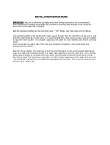
THE BASIC REVERSE OSMOSIS SYSTEM cont.
1.5" Air Gap Required
Inlet-1/2" White
Drain - 3/8" Black Purified Water - 3/8" Blue
Feed Water Valve
Cold Water Line Only
Feed Pressure
Gauge
Optional Pre-Evolution
™
Pre-Filter
Pure Water Storage Tank
To Point of Use
Optional 3/8” Float Valve
Typical Light Commercial Installation with Storage Tank
5

INSTALLATION
STEP 1: Install cold water supply fitting. Use either the included
garden hose connector or any of the other optional feed fittings.
STEP 2: Install optional drain adapter
STEP 3: Make tubing connections
STEP 4: Install RO assembly
STEP 5: Put system into operation
NOTE: Consult a licensed plumber if you are not familiar with
plumbing procedures.
Step 1: Install Cold Water Supply Fitting
A female garden hose thread connector fitting is included to be able
to hook up to a garden hose or hose bib (spigot). Keep the length
of garden hose as short as possible to minimize pressure loss. A
variety of other feed fitting and feed valves are available to be able to
connect to other existing plumbing. Check with your dealer or contact
Hydro-Logic. Comply with local plumbing codes.
WATER SUPPLY VALVE
NOTE: Be sure to turn off the water supply before installation
Cold water pipes vary in size and style. The installer will determine
type of valve that will be used. Install a valve on the cold water
supply pipe to adapt 1/2-inch OD tubing. If threaded fittings are used,
be sure to use pipe joint compound or Teflon tape on outside threads.
Turn the valve off.
Step 2: Direct black drain line to an appropriate drain
location or install optional drain adapter.
The optional 3/8” quick connect drain adapter must be installed on
the main sink drain above the P-trap. The drain adapter is designed
to fit 1-1/2-inch (3.8 cm) sink drain pipe. The black drain line may also
be directed directly into a drain point or outside. The drain water
can be re-used for a variety of applications including watering your
landscape plants, trees, shrubs and lawns. The drain (waste) water
contains the majority of the contaminants in your source (tap) water.
The PPM’s of the drain water are typically 33% higher than the
source water. A certain amount of drain water in necessary to flush
the contaminants away from the membranes and prevent them from
fouling or scaling prematurely. DO NOT restrict the black drain line.
Let it flow freely.
6

NOTE: Make sure the tubing is pushed past the O-rings for a
secure fit. Also, when replacing any tubing, cut tubing
back ~1/4 inch prior to re-inserting to prevent leaks.
INSTALLATION cont.
Step 3: Make Tubing Connections
The connections to the faucet should be complete, the remaining
connections are:
Feed connection—white 1/2” tubing from feed fitting or feed •
valve to pressure gauge and then to white elbow connector
Drain connection—black 3/8” tubing from green elbow •
connection will attach to the optional drain adapter or be
directed to appropriate drain location
Purified water connection—blue 3/8” tubing blue elbow •
connection to reservoir or tank via optional 3/8” float valve
Attach the fittings to the manifold•
A typical connection is shown in Figure 7 Side View and Cutaway of
Tubing Fitting.
NOTE: For optimal system performance, we recommend using tubing
lengths that are as short as possible.
Feed Pressure Gauge w/ "T" fitting
The supplied pressure gauge should be connected to the feed line to
monitor system feed pressure. For proper system performance, the
inlet feed pressure must be between 40 psi (2.76 bar) and 80 psi (5.52
bar) when the system is in operation. Insert the short length of tubing
into the white elbow connector. Then install pressure gauge w/ “T”
fitting. Then install long length of white tubing to other end of pressure
gauge “T” fitting.
Inline Shut-off Valve
The supplied 3/8" inline shut-off valve is designed to be installed on
the blue pure water line. Thje system can be shut-off by using this
valve.
Step 4: Install RO Assembly
The RO Assembly includes the following components: sumps (3),
support leg, carbon pre-filter, and RO membrane elements (2). The
tubing is attached to the manifold by the elbow connectors. When
choosing a location for the system, allow enough tubing for it to be
moved for periodic servicing of the pre- filter and membrane elements
(Figure 8 RO Assembly).
WARNING:
Do not attempt to mount/hang the system. Do not
try to drill mounting holes anywhere on the system.
If putting above ground/cabinet level, a sturdy,
permanent shelf is recommended.
O-Ring
O-Ring
Collet
Tubing
Collet
Lock Clip
Side View and Cutaway of Tubing FittingFigure 1
RO AssemblyFigure 2
Support Leg
RO
Membranes
Prefilter
Sumps
Manifold
Elbow
Connectors
7

Recommended Placement Positions
The RO assembly should be positioned in one of two ways.
The first position is with the unit standing upright using the support
leg with the sumps horizontal. The tubing is directed to provide the
best fit.
The second position, sets the unit on end so the sumps are pointing
up. The tubing is directed upward and the locking bar is down to lock
the tubing connections. See Figure 9 System Positions.
NOTE: Ensure that the support leg is installed on the sumps.
Connection Lubrication
Connections with O-rings must be properly lubricated. The following
instructions describe the method and locations for lubrication.
Six packets of silicone lube are supplied. One packet should be
completely used to lubricate the O-ring contact surfaces in the 3
manifold ports and 2 RO membrane locations (Figure 10). Follow
Figure 11 and lubricate the filter seat and the flat surface below the
threads for the 3 sump locations. Use a complete packet of silicone
for each sump location.
NOTE: To properly lubricate the O-ring contact area, a film of clean
silicone grease is applied. The film should cover all of the
surface area that the O-ring will slide over and seal with. Do
not use grease containing petroleum products.
NOTE: The Quick Start guide indicates applying the lube directly to
the O-rings as opposed to the contact surfaces of the O-rings.
Either method is appropriate.
NOTE: Please save extra lube packs for future membrane changes.
Extra lube packs can be sourced through your dealer, Hydro-
Logic, plumbing supply stores, or hardware stores.
INSTALLATION cont.
System PositionsFigure 3
First Position
Locking Bar
Second Position
Support Leg
Figure 4
Figure 5
8

Tested @ 77F and 500 PPM source water. Flow rates will vary depending
on source water, temperature and PPM’s.
IMPORTANT NOTE:
The flow rate of product water can drastically decrease due to low psi and
low temperature, especially in the winter. In some cases with cold tempera-
ture and/or low pressure predicted flow rate can drop by as much as 50%
or more. A combination of cold water and low pressure can drop flow
rates even further. This is the case with all Reverse Osmosis technology and
is not unique to the Evoution-RO1000. The ratio of waste water to product
water can also get drastically worse due to low pressure and low tempera-
ture. You can overcome some of these issue by increasing pressure with an
optional booster pump, HL#29014, or increasing inlet temperature. We do
not recommend hooking the Evolution up to your hot water tank lines
because hot water tanks contain lots of minerals and the water can be too
hot. A safe way to increase temperature is with an on demand or flash style
water heater set at below 100F or 37.7C. For people with adequate
pressure but decreased water temperature a flash water heater is a great
way to increase flow rates.
The flow rate of purified water will vary depending on 3 factors:
Temperature Compensation Factor Chart:
www.evolutionRO1000.com/TCF

TO CARE FOR THE RO SYSTEM
The components of the RO system are designed to function with
minimal maintenance. However, the membrane elements and pre-
filter will need to be replaced on a regular schedule.
For optimal performance the system should be flushed for 2 minutes if
periods of inactivity that extend past six hours.
REPLACEMENT OF PRE-FILTER
The carbon pre-filter reduces sediment and certain chemicals, such
as chlorine, from the water. Depending on water use and the amount
of impurities, this filter should be replaced a minimum of 2,000 gallons
of purified water produced.
Applications using more than an average of 20 gallons purified water
per day should install the optional Pre-Evolution high capacity pre-
filter to further reduce chlorine, sediment, and other contaminants.
REPLACEMENT OF RO MEMBRANE ELEMENTS
The functional life of the RO membrane elements will vary based
on feed water quality. Product water should be tested periodically
to verify the membrane elements are performing properly. For most
applications, the RO membrane elements should be replaced every 6
months to two years.
NOTE: Softened water is recommended for optimal system
performance and RO membrane element life.
REPLACEMENT OF THE PRE-FILTER,
AND RO MEMBRANE ELEMENTS
Turn off the water supply to the RO System. 1.
Reduce system water pressure by opening the included shut off 2.
valve or optional float valve.
CAUTION:
Even with the water supply turned off the membrane and
pre-filter sumps will contain a considerable amount of
water. By positioning the RO assembly in a sink or tub,
most of the water will be contained.
Disconnect locking bar and place the fittings (with tubing still
3.
connected) into a tub or bucket.
Move system into a contained area, such as a sink or tub.
4.
Remove the support leg from the three sumps and unscrew the 5.
top sump as shown to access the pre-filter. The support leg
functions as a wrench to loosen the sump, Figure 13.
NOTE: There is no need to disconnect tubing from fittings on the
manifold. Remove locking bar and pull fittings out. Lubricate
O-rings with silicone prior to re-assembly.
NOTE: If changing only the pre-filter the other sumps do not need
to be removed. If changing the membrane elements, the pre-
filter should also be changed.
Remove exhausted pre-filter and discard.6.
CAUTION:
The person handling the filters and membrane elements
must have clean hands to keep the system sanitized. The
use of sterile/latex gloves is recommended.
Figure 7
10

If changing membrane elements:7.
Remove membrane sumps. Remove and discard used a.
elements.
Remove new elements from packaging.
b.
CAUTION:
Elements contain a foodgrade preservative. The use of
sterile/latex gloves is highly recommended.
Lubricate element O-rings, brine seals, and sump O-rings
c.
with silicone lubricant. Refer to "Connection Lubrication"
on page 8 for correct lubrication procedure of elements
cartridge.
Securely insert O-ring end of elements into manifold. See
d.
Figure 13.
Replace sumps and tighten until it bottoms out.
e.
NOTE: The system should be sanitized whenever a
membrane element or filter is replaced.
Sanitize the system.
8.
The manifold should be positioned flat with the sump a.
connections facing up.
Pour a tablespoon (15 milliliters) of chlorine bleach into
b.
the center opening of the prefilter sump connection. See
Figure 14.
Install pre-filter.
9.
Remove new prefilter from packaging. Ensure gaskets are a.
secure. Insert prefilter into proper opening on manifold.
Lubricate sump O-ring with silicone lubricant.
b.
With the pre-filter element in place, screw the sump into c.
the connection. Tighten until it bottoms out.
Re-connect the fittings to the manifold and lock in position with
10.
locking bar.
Re-position the assembly and turn the water supply on. Check the
11.
system for any leaks.
CAUTION:
Water may sputter from the air gap until the trapped air
is purged.
Open the shut off valve or float valve and run water for two
12.
minutes.
Shut off the shut off valve or float valve and allow the system to
13.
stand idle for 20 to 30 minutes.
Open the shut off valve or float valve and run water for five
14.
minutes.
Check for any system leaks.
15.
NOTE: If the two RO membrane elements were replaced the system
must be flushed according to Step 6 the system startup
procedure as stated above.
The RO system is now ready for use.
REPLACEMENT OF THE PRE-FILTER,
AND RO MEMBRANE ELEMENTS cont.
Figure 8
Membrane Element
Locations
Prefilter Center Opening
NOTE: For long-term storage of the unit you must store both
membranes in a sealed plastic bag in the refrigerator. Do
not let the membranes dry out. It is OK to store the carbon
pre-filter dry.
11

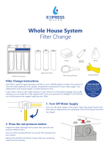
Performance Specifications
Minimum and Maximum Operating Conditions
Condition Minimum Maximum
Inlet Pressure 40 psi (2.76 bar) 80 psi (5.52 bar)
Inlet Temperature 40°F (4.44°C) 100°F (37.78°C)
Inlet TDS 50 PPM 1,000 PPM
Inlet Hardness 0 mg/L (0 grain) 171 mg/L (10 grain)
Inlet Chlorine 0 mg/L 1.0 mg/L
Inlet Iron 0 mg/L 0.1 mg/L
Inlet Manganese 0 mg/L 0.05 mg/L
Inlet pH 4 10
Inlet Turbidity 0 1 NTU
12
Silica 0 mg/L 3 mg/L

TROUBLESHOOTING
Issue Possible Cause Corrective Action
Low product flow
rate
Low driving pressure.
Increase feed pressure. Consider pump for low pressure locations.
Use short tubing runs to decrease flow restriction. Increase tubing
diameter for longer distances.
Low water temperature or high total dissolved solids (TDS). Increase feed water temperature or feed pressure to compensate.
Plugged prefilter.
Replace plugged prefilter. Consider sediment prefilter for non-
chlorinated applications.
Scaled or fouled RO membrane. Replace membranes.
Leak or kink in product line. Find and repair leak or kink.
Concentrate water
runs to drain after
faucet shut off
Plugged prefilter
Replace plugged prefilter. Consider sediment prefilter for non-
chlorinated applications.
Leak in product line.
Find and repair leak. Install pressure gauge in product line to help
identify a product pressure leak.
Poor product water
quality
Water sample taken during system flush. Take sample after three minutes of continuous operation.
Low driving pressure.
Increase feed pressure. Consider pump for low pressure locations.
Use short tubing runs to decrease flow restriction. Increase tubing
diameter for longer distances.
Plugged pre-filter.
Replace plugged prefilter. Consider sediment prefilter for non-
chlorinated applications.
Scaled, fouled, or damaged RO membrane. Replace RO membranes.
Membrane stem o-rings damaged during installation
Replace both o-rings on membrane stem and lube properly before
installing
Hydro-Logic Purification Systems
370 Encinal Street, Suite 150
Santa Cruz, CA 95060
P: 888.426.5644
F: 831.336.9840
www.hydrologicsystems.com
For available options and add-ons,
contact Hydro-Logic directly
13

NOTES:
___________________________________________
___________________________________________
___________________________________________
___________________________________________
___________________________________________
___________________________________________
___________________________________________
___________________________________________
___________________________________________
___________________________________________
___________________________________________
___________________________________________
___________________________________________
___________________________________________
___________________________________________
___________________________________________
___________________________________________
___________________________________________
___________________________________________
___________________________________________
___________________________________________
___________________________________________
14

GL4000442 RevA
-
 1
1
-
 2
2
-
 3
3
-
 4
4
-
 5
5
-
 6
6
-
 7
7
-
 8
8
-
 9
9
-
 10
10
-
 11
11
-
 12
12
-
 13
13
-
 14
14
-
 15
15
-
 16
16


Hydrologic EVOLUTION-RO1000 Operating instructions
- Category
- Water dispensers
- Type
- Operating instructions
Ask a question and I''ll find the answer in the document
Finding information in a document is now easier with AI
Related papers


Other documents
-
 Anchor USA AF-6002 Operating instructions
-
 Hydro-Logic Purification Systems Evolution-RO Owner's manual
-
vitapur VPS1140-1 User guide
-
No Brand RO300, 110-120 V User manual
-
 Express Water FLTWH2045C10 User manual
-
Electrolux WE 2000 E User manual
-
unknown RO300 User manual
-
-
 PRO+AQUA PRO-RO-I Operating instructions
-
 Express Water FLTWH1045C02 User manual


