
DLT
TM
4000/DLT
TM
4500/DLT
TM
4700
Cartridge Tape Subsystem
Product Manual


DLT
TM
4000/DLT
TM
4500/DLT
TM
4700
Cartridge Tape Subsystem
Product Manual
March 10, 1996
81-60043-01

Quantum reserves the right to make changes and improvements to its products, without
incurring any obligation to incorporate such changes or improvements in units previously
sold or shipped.
You can request Quantum publications from your Quantum Sales Representative, or order
them directly from Quantum.
Publication Number: 81-60043-01
SERVICE CENTERS
Quantum Service Center
715 Sycamore Avenue
Milpitas, California 95035
Phone (408) 894-4000
Fax: (408) 894-3218
Quantum Asia-Pacific Pte. Ltd.
50 Tagore Lane #b1-04
Singapore, 2678
Phone: (65) 450-9333
Fax (65) 452-2544
DLTtape is a trademark of Quantum Corporation.
DLT is a trademark of Quantum Corporation.
Copyright 1996 by Quantum Corporation. All rights reserved. Printed in USA.

The following FCC Notice applies to the DLT
TM
4000 drive:
FCC NOTICE: This equipment has been tested and found to comply with the limits for a
Class A digital device, pursuant to Part 15 of the FCC rules. These limits are designed to
provide reasonable protection against harmful interference in residential installation. Any
changes or modifications made to this equipment may void the user’s authority to operate this
equipment.
This equipment generates, uses, and radiates radio frequency energy and, if not installed and
used in accordance with the instructions, may cause harmful interference to radio
communications. However, there is no guarantee that interference will not occur in a
particular installation. If this equipment does cause harmful interference to radio or television
reception, which can be determined by tuning the equipment off and on, the user is
encouraged to try to correct the interference by one or more of the following measures:
1. Reorient or relocate the receiving antenna.
2. Increase the separation between the equipment and receiver.
3. Connect the equipment into an outlet on a circuit different from that to which the
receiver is connected.
4. Consult the dealer or an experienced radio/TV technician for help. The shielded
interconnect cable shipped with the unit should not be altered or modified in any way.
The unit shipped without a shielded interconnect cable must use a shielded interconnect
cable.
The user may find the following booklet prepared by the Federal Communications
Commission helpful: How to Identify and Resolve Radio-TV Interference Problems. This
booklet is available from the U.S. Government Printing Office, Washington D.C., 20402.
Stock No. 004-00398-5.
All external I/O cables connecting to this unit need to be shielded. See the User Manual or
installation instructions for more options.
This digital apparatus does not exceed the Class B limits for radio noise emissions set out in
the radio interference regulations of the Canadian Department of Communications.
This equipment is in the 2nd Class Category (information equipment to be used in a
residential area or an adjacent area thereto) and conforms to the standards set by the
Voluntary Control Council For Interference by Data Processing Equipment and Electronic
Office Machines aimed at preventing radio interference in such residential area.
This equipment meets or exceeds requirements for safety in the U.S. (UL 1950), Canada
(CSA C22.2 N0. 950) and Europe (EN60950/IEC 950) requirements, and is certified to bear
the GS mark by TUV.

The following FCC Notice applies to the DLT
TM
4500 and DLT
TM
4700 mini-libraries:
FCC NOTICE: This equipment has been tested and found to comply with the limits for a
Class A device, pursuant to Part 15 of the FCC Rules. These limits are designed to provide
reasonable protection against harmful interference when the equipment is operated in a
commercial environment. This equipment generates, uses and can radiate radio frequency
energy and, if not installed and used in accordance with the instruction manual, may cause
harmful interference to radio communications. Any changes or modifications made to this
equipment may void the user’s authority to operate this equipment. Operation of this
equipment in a residential area may cause interference in which case the user at his own
expense will be required to take whatever measures may be required to correct the
interference. The shielded interconnect cable shipped with the unit should not be altered or
modified in any way. The unit shipped without a shielded cable must use a shielded
interconnect cable.
Warning! This is a Class A product. In a domestic environment this product may cause radio
interference in which case the user may be required to take adequate measures.
Achtung! Dieses ist ein Gerat der Funkstorgenzwertklasse A. In Wohnbereicghen konnen
bei Betrieb dieses Gerates Runfunkstorungen auftreten, in welchen Fallen der Benutzer fur
entsprechende GengenmaBnahmen verantwortlich ist.
Attention! Ceci est un produit de Classe A. Dans un environment domestique, ce produit
risque de creer des interferences radioelectriques, il appartiendra alors a l'utilisateur de
prendre les mesures specifiques appropriees.

DLT4000\DLT4500\DLT4700 Cartridge Tape Subsystem-v
Table of Contents
Chapter 1: Overview and Features of the DLT4000/DLT4500/DLT4700
Product
1.1 In This Chapter ..............................................................................................1-1
1.2 Product Overview ...........................................................................................1-1
1.3 Fast Data Transfer Rate ..................................................................................1-2
1.4 High-Capacity.................................................................................................1-2
1.5 Compaction ....................................................................................................1-2
1.6 Strong Media..................................................................................................1-3
1.7 Compatibility..................................................................................................1-3
1.8 Firmware Update Capability ...........................................................................1-3
1.9 Embedded Diagnostics....................................................................................1-3
Chapter 2: Installing and Configuring the DLT4000 Tabletop
2.1 In This Chapter ..............................................................................................2-1
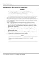
2.2 Prepare for the Installation.............................................................................. 2-1
2.2.1 Before You Start..................................................................................... 2-1
2.2.2 Installation Setup ...................................................................................2-2
2.2.3 Site Setup............................................................................................... 2-2
2.2.4 Site Guidelines.......................................................................................2-2
2.3 Install the Drive.............................................................................................. 2-4
2.4 Configure the DLT4000 Tabletop ...................................................................2-5
2.4.1 Configuration Guidelines .......................................................................2-5
2.4.2 DISABLE PARITY Checking ................................................................2-5
2.4.3 Changing the SCSI ID............................................................................ 2-5
2.5 Connect the Cables......................................................................................... 2-7
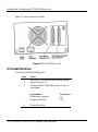
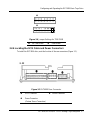
2.5.1 Examine the DLT4000 Rear Panel .........................................................2-7

Contents
vi-DLT4000\DLT4500\DLT4700 Cartridge Tape Subsystem
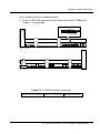
2.5.2 Connect the SCSI Signal Cable.............................................................. 2-7
2.5.3 Terminate the SCSI Bus......................................................................... 2-8
2.5.4 Connect the Power Cord......................................................................... 2-8
2.6 Test the Installation........................................................................................ 2-9
2.6.1 Run POST.............................................................................................. 2-9
2.6.2 What to Do after POST ........................................................................ 2-10
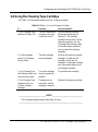
2.7 DLT4000 Troubleshooting Chart.................................................................. 2-11
Chapter 3: Configuring and Operating the DLT4000 Drive
3.1 In This Chapter .............................................................................................. 3-1
3.2 Before You Install the DLT4000 Drive........................................................... 3-1
3.2.1 Disabling Parity Checking...................................................................... 3-2
3.2.2 Changing the SCSI ID ........................................................................... 3-5
3.2 3 Setting the TRM ENB (Single-ended only) Jumper ................................ 3-6
3.2 4 Locating the SCSI Cable and Power Connectors..................................... 3-7
3.3 Selecting Density............................................................................................ 3-8
3.4 Overview of the Front Panel ......................................................................... 3-11
3.5 Description of Controls and Indicators.......................................................... 3-12
3.5.1 Beeper.................................................................................................. 3-12
3.5.2 Unload Button...................................................................................... 3-12
3.5.3 Cartridge Insert/Release Handle........................................................... 3-12
3.5.4 Indicator Action during Power-On Self Test and Operation.................. 3-13
3.6 Description of the Tape Cartridge................................................................. 3-17
3.6.1 Cartridge Write-Protect Switch ............................................................ 3-17
3.6.2 Data Protection .................................................................................... 3-19
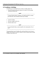
3.7 Loading a Cartridge...................................................................................... 3-20
3.7.1 Tape in Use.......................................................................................... 3-22
3.8 Using the Cleaning Tape Cartridge............................................................... 3-23
3.9 Unloading a Cartridge.................................................................................. 3-24

Contents
DLT4000\DLT4500\DLT4700 Cartridge Tape Subsystem-vii
3.10 Preserving Cartridges.................................................................................. 3-26
Chapter 4: Configuring and Operating the DLT4500 Mini-Library
4.1 In This Chapter ..............................................................................................4-1
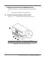
4.2 Introduction to the DLT4500 Mini-Library.....................................................4-2
4.3 Configure the DLT4500 Mini-Library.............................................................4-3
4.4.1 Location of Controls, Switches, and Connectors .....................................4-3
4.4.2 Configuration guidelines ........................................................................4-7
4.4.3 SCSI ID, setting .....................................................................................4-7
4.4.4 Connecting the SCSI Signal Cable .........................................................4-8
4.5 Installation testing.......................................................................................... 4-9
4.5.1 Run POST..............................................................................................4-9
4.5.2 What to Do after POST ..........................................................................4-9
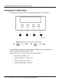
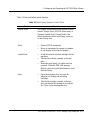
4.6 Operator Control Panel................................................................................. 4-12
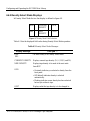
4.6.1 Normal Mode Displays......................................................................... 4-14
4.6.2 Density Select Mode Displays............................................................... 4-16
4.6.3 SCSI ID Select Mode............................................................................ 4-18
4.7.4 Firmware Update Mode........................................................................ 4-19
4.8 Key lock ....................................................................................................... 4-20
4.8.1 OCP, locked or OCP, Disabled............................................................. 4-20
4.8.2 OCP, Unlocked or Enabled................................................................... 4-20
4.9 Selecting density........................................................................................... 4-21
4.9.1 Front panel, density select .................................................................... 4-21
4.9.2 Host selection, density.......................................................................... 4-23
4.9.3 Native default, density.......................................................................... 4-23
4.10 Description of the Tape Cartridge............................................................... 4-24
4.10.1 Tape Cartridge, positioning the write-protect switch........................... 4-24
4.10.2 Data protection................................................................................... 4-25
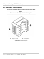
4.11 Description of the Magazine .......................................................................4-26

Contents
viii-DLT4000\DLT4500\DLT4700 Cartridge Tape Subsystem
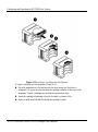
4.11.1 Insert cartridge, magazine.................................................................. 4-27
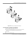
4.11.2 Removing cartridge............................................................................ 4-29
4.11.3 Magazine, removing from mini-library............................................... 4-30
4.11.4 Magazine, installing........................................................................... 4-30
4.11.5 Selecting a Cartridge from the Magazine............................................ 4-31
4.11.6 Loading cartridge into the Drive......................................................... 4-31
4.11.7 Unloading cartridge from the drive..................................................... 4-32
4.11.8 Opening the Magazine Door............................................................... 4-32
4.12 When to Use the Cleaning Tape Cartridge.................................................. 4-33
Chapter 5: Configuring and Operating the DLT4700 Mini-Library
5.1 In This Chapter .............................................................................................. 5-1
5.2 Introduction to the Mini-Library..................................................................... 5-1
5.3 Configuring the DLT4700 Mini-Library......................................................... 5-2
5.3.1 Configuration Guidelines ....................................................................... 5-3
5.3.2 Disable Parity Checking......................................................................... 5-3
5.3.3 Change the SCSI ID............................................................................... 5-3
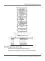
5.4 Mode Select Key............................................................................................. 5-5
5.4.1 OCP Disabled Mode............................................................................... 5-5
5.4.2 Automatic Mode..................................................................................... 5-7
5.4.3 Manual Mode......................................................................................... 5-7
5.4.4 Service Mode ......................................................................................... 5-8
5.5 Selecting Density............................................................................................ 5-9
5.6 Operator Control Panel................................................................................. 5-12
5.7 Power-On Process......................................................................................... 5-16
5.8 Slot Select, Load/Unload .............................................................................. 5-18
5.8.1 Selecting a Cartridge............................................................................ 5-18
5.8.2 Loading the Cartridge .......................................................................... 5-18
5.8.3 Unloading the Cartridge....................................................................... 5-19

Contents
DLT4000\DLT4500\DLT4700 Cartridge Tape Subsystem-ix
5.8.4 Opening the Receiver ...........................................................................5-20
5.9 Magazine...................................................................................................... 5-21
5.9.1 Inserting a Cartridge ............................................................................ 5-21
5.9.2 Removing a Cartridge from the Magazine............................................ 5-24
5.9.3 Removing the Magazine from the Receiver........................................... 5-24
5.9.4 Installing the Magazine into the Receiver............................................. 5-24
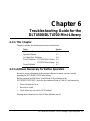
Chapter 6: Troubleshooting Guide for the DLT4500/DLT4700 Mini-
Library
6.1 In This Chapter ..............................................................................................6-1
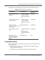
6.2 Conditions Necessary for Button Operation..................................................... 6-1
6.3 Operation Failure............................................................................................ 6-3
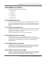
6.4 Avoiding Basic Problems................................................................................6-4
6.5 DLT4500 Error Conditions............................................................................. 6-5
6.5.1 DLT4500 Magazine Error......................................................................6-5
6.5.1.1 DLT4500 Clearing a Magazine Error..............................................6-5
6.5.2 DLT4500 Loader Error Description........................................................6-5
6.5.3 DLT4500 Drive Error Description.......................................................... 6-5
6.5.4 DLT4500 Controller Error Description................................................... 6-5
6.5.5 DLT4500 Unknown Error Description ...................................................6-6
6.5.5.1 DLT4500 Clearing a Loader, Drive, Controller, or Unknown Error 6-6
6.6 DLT4700 Error Conditions............................................................................. 6-6
6.6.1 DLT4700 Magazine Fault Cases............................................................. 6-6
6.6.2 DLT4700 Loader Fault Description........................................................6-8
6.7 Power Problems..............................................................................................6-9
Chapter 7: Firmware Update
7.1 In This Chapter ..............................................................................................7-1
7.2 DLT4000 Firmware Update Overview ............................................................7-1

Contents
x-DLT4000\DLT4500\DLT4700 Cartridge Tape Subsystem
7.2.1 Updating firmware on a Standalone System ........................................... 7-2
7.3 Creating a Firmware Update Tape.................................................................. 7-4
7.3.1 On UN*X Systems................................................................................. 7-4
7.4 Firmware Update Procedure............................................................................ 7-6
7.4.1 Updating the Firmware on DLT4000 (Drive Only Configuration) .......... 7-6
7.4.2 Updating the Firmware on the DLT4500 (Drive and Loader
Configuration) ................................................................................................ 7-9
7.4.3 Updating the Firmware on the DLT4700 (Drive and Loader
Configuration) .............................................................................................. 7-14
Chapter 8: DLT4000 SCSI Interface
8.1 Overview........................................................................................................ 8-1
8.2 General SCSI Bus Operations......................................................................... 8-1
8.2.1 Data Transfer......................................................................................... 8-1
8.2.2 Initiator/Target Operations..................................................................... 8-2
8.2.3 SCSI IDs and Logical Unit Numbers (LUNs) ......................................... 8-2
8.2.4 Unit Attention Condition........................................................................ 8-3
8.2.5 Behavior Around Power-On and SCSI Bus Reset ................................... 8-3
8.2.6 Data Cache and Tape Write Interaction.................................................. 8-4
8.2.7 Other SCSI Functionality....................................................................... 8-4
8.2.8 Bus Phases............................................................................................. 8-4
8.2.9 ATTENTION Signal Response .............................................................. 8-4
8.2.10 STATUS phase .................................................................................... 8-5
8.2.11 BUS FREE........................................................................................... 8-6
8.2.12 BUS PARITY ERRORS....................................................................... 8-6
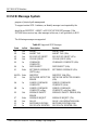
8.3 SCSI Message System..................................................................................... 8-8
8.4 Tape Drive SCSI Commands........................................................................ 8-14
8.4.1 Control Byte - Flag and Link Bits......................................................... 8-14
8.4.2 Summary of Supported Sequential-Access Device Commands.............. 8-15

Contents
DLT4000\DLT4500\DLT4700 Cartridge Tape Subsystem-xi
8.4.3 ERASE (19h)....................................................................................... 8-16
8.4.4 INQUIRY (12h) ................................................................................... 8-17
8.4.4.1 Drive Inquiry Response................................................................. 8-18
8.4.4 2 Vendor Unique Inquiry................................................................. 8-21
8.4.4.3 Vital Product Data Pages ..............................................................8-23
8.4.4.4 Media Loader Inquiry Response.................................................... 8-24
8.4.5 LOAD-UNLOAD (1Bh)....................................................................... 8-25
8.4.6 LOCATE (2Bh).................................................................................... 8-27
8.4.7 LOG SELECT (4Ch)............................................................................ 8-28
8.4.7.1 Operation of LOG SELECT.......................................................... 8-30
8.4.8 LOG SENSE (4Dh)..............................................................................8-34
8.4.8.1 Supported Pages Page Format....................................................... 8-37
8.4.8.2 Read/Write Error Log SENSE Page Format (Page 2 and 3)........... 8-38
8.4.8.3 Last n Error Events Page (07h)..................................................... 8-41
8.4.8.4 Read/Write Compression Ratio Log SENSE Page Format............. 8-42
8.4.9 MODE SELECT (15h)......................................................................... 8-46
8.4.9.1 MODE SELECT Parameter List ................................................... 8-47
8.4.9.2 MODE SELECT Pages................................................................. 8-50
8.4.9.3 Read/Write Error Recovery Page (01h) .........................................8-51
8.4.9.4 Disconnect/Reconnect Page (02h) ................................................. 8-53
8.4.9.7 Control Mode Page (0Ah)............................................................. 8-56
8.4.9.8 Data Compression Page (0Fh)....................................................... 8-58
8.4.9.5 Device Configuration Page (10h) .................................................. 8-60
8.4.9.6 Medium Partition Page (11h)........................................................ 8-63
8.4.9.9 EEROM Vendor Unique Page (3Eh)............................................. 8-64
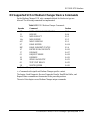
8.4.9.10 MODE SELECT Changeable Parameters.................................... 8-70
8.4.10 MODE SENSE (1Ah /5Ah)................................................................ 8-71
8.4.10.1 MODE SENSE Parameter List.................................................... 8-74
8.4.10.2 MODE SENSE Pages.................................................................. 8-78

Contents
xii-DLT4000\DLT4500\DLT4700 Cartridge Tape Subsystem
8.4.10.3 Read/Write Error Recovery Page................................................. 8-79
8.4.10.4 Disconnect/Reconnect Page......................................................... 8-81
8.4.10.7 Control Mode Page (0Ah)........................................................... 8-82
8.4.10.8 Data Compression Page (0Fh)..................................................... 8-84
8.4.10.5 Device Configuration Page (10h)................................................ 8-86
8.4.10.6 Medium Partition Page (11h)...................................................... 8-88
8.4.10.9 EEROM Vendor Unique Page (3Eh)........................................... 8-89
8.4.11 PREVENT/ALLOW MEDIUM REMOVAL (1Eh)............................. 8-90
8.4.12 READ (08h)....................................................................................... 8-91
8.4.13 READ BLOCK LIMITS (05h) ........................................................... 8-93
8.4.14 READ BUFFER (3Ch)....................................................................... 8-94
8.4.14.1 Combined Header and Data Mode............................................... 8-95
8.4.14.2 Data Mode.................................................................................. 8-95
8.4.14.3 Descriptor Mode......................................................................... 8-95
8.4.15 READ POSITION (34h)..................................................................... 8-97
8.4.15.1 READ POSITION Data Format.................................................. 8-98
8.4.16 RECEIVE DIAGNOSTICS RESULTS (1Ch)....................................8-100
8.4.17 RELEASE UNIT (17h) .....................................................................8-101
8.4.17.1 Medium Changer Considerations...............................................8-101
8.4.18 REQUEST SENSE (03h) ..................................................................8-102
8.4.18.1 Sense Information Format..........................................................8-103
8.4.19 RESERVE UNIT (16h) .....................................................................8-112
8.4.19.1 Medium Changer Considerations...............................................8-113
8.4.20 REWIND (01h).................................................................................8-114
8.4.21 SEND DIAGNOSTIC (1Dh).............................................................8-115
8.4.22 SPACE (11h) ....................................................................................8-120
8.4.23 TEST UNIT READY (00h)...............................................................8-122
8.4.23.1 Medium Changer Considerations...............................................8-122
8.4.24 VERIFY (13h) ..................................................................................8-123

Contents
DLT4000\DLT4500\DLT4700 Cartridge Tape Subsystem-xiii
8.4.25 WRITE (0Ah) ................................................................................. 8-124
8.4.26 WRITE BUFFER (3Bh).................................................................... 8-126
8.4.26.1 Header and Data Mode.............................................................. 8-127
8.4.26.2 Write Data................................................................................ 8-127
8.4.26.3 Download Microcode................................................................ 8-127
8.4.26.4 Download Microcode and Save ................................................. 8-127
8.4.27 WRITE FILEMARKS (10h)............................................................. 8-129
8.5 Supported SCSI-2 Medium Changer Device Commands............................. 8-131
8.5.1 INITIALIZE ELEMENT STATUS (07h) .......................................... 8-132
8.5.2 MODE SENSE/SELECT (1Ah/15h)................................................... 8-133
8.5.2.1 Device Capabilities Page (1Fh) ................................................... 8-133
8.5.2.2 Element Address Assignment Page (1Dh)................................... 8-135
8.5.2.3 Transport Geometry Parameters Page (1Eh)................................ 8-137
8.5.3 MOVE MEDIUM (A5h) .................................................................... 8-138
8.5.4 READ ELEMENT STATUS (B8h) .................................................... 8-139
8.5.4.1 Element Status Data Header........................................................ 8-140
8.5.4.2 Medium Transport Element Status Page...................................... 8-141
8.5.4.3 Storage Element Status Page....................................................... 8-142
8.5.4.4 Data Transfer Element Status Page............................................. 8-143
Appendix A: Technical Specifications
A.1 In This Appendix.......................................................................................... A-1
A.2 Drive and Mini-library Physical Descriptions................................................ A-2
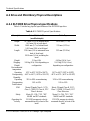
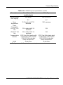
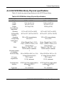
A.2.1 DLT4000 Drive Physical Descriptions.................................................. A-2
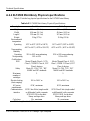
A.2.2 DLT4500 Mini-library Physical Descriptions........................................ A-4
A.2.3 DLT4700 Mini-library Physical Descriptions........................................ A-5
A.3 Drive Functional Description........................................................................ A-6
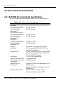
A.3.1 DLT4000 Drive Functional Description................................................ A-6
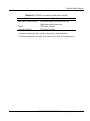
A.4 Identifying the Correct AC Power Cord......................................................... A-8

Contents
xiv-DLT4000\DLT4500\DLT4700 Cartridge Tape Subsystem
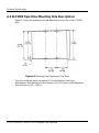
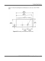
A.5 DLT4000 Tape Drive Mounting Hole Descriptions......................................A-10
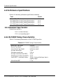
A.6 Performance Specifications..........................................................................A-12
A.6.1 Nominal Tape Tension........................................................................A-12
A.6.2 DLT4000 Timing Characteristics........................................................A-12
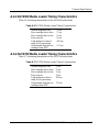
A.6.3 DLT4500 Media Loader Timing Characteristics..................................A-13
A.6.4 DLT4700 Media Loader Timing Characteristics..................................A-13
A.7 Environmental Specifications ......................................................................A-14
A.7.1 Temperature and Humidity..................................................................A-14
A.7.2 Altitude...............................................................................................A-15
A.8 Vibration and Shock Specifications..............................................................A-16
A.8.1 Operating Shock and Vibration ...........................................................A-16
A.8.2 Nonoperating Shock and Vibration......................................................A-17
A.9 Electromagnetic Interference (EMI) Susceptibility.......................................A-21
A.9.1 Electromagnetic Emissions..................................................................A-21
A.9.2 Conducted Emissions ..........................................................................A-22
A.9.3 Radiated Emissions .............................................................................A-22
A.9.4 Magnetic Radiated Susceptibility.........................................................A-22
A.9.5 Radiated Susceptibility ........................................................................A-23
A.9.6 Conducted Susceptibility .....................................................................A-23
A.9.7 ESD Failure Level Limits....................................................................A-24
A.9.8 Acoustic Noise Emissions....................................................................A-24
A.10 Regulatory Requirements...........................................................................A-26
A.10.1 Safety Requirements..........................................................................A-26
A.10.2 Electromagnetic Emission Requirements...........................................A-26
A.11 Drive Reliability Factors ............................................................................A-27
A.12 DLTtape Recording Media Specifications ..................................................A-28
Appendix B: Definition of Vendor Unique Sense Data Information
B.1 In This Appendix...........................................................................................B-1

Contents
DLT4000\DLT4500\DLT4700 Cartridge Tape Subsystem-xv
B.2 Internal Status................................................................................................B-1
Appendix C: Sense Key Information
C.1 In This Appendix...........................................................................................C-1
Appendix D: EEROM Resident Bugcheck and Event Logs
D.1 EEROM Packets (Last n Error Events).......................................................... D-1
D.2 Bugcheck Packets ......................................................................................... D-2
D.3 PO/ST failure packets ................................................................................... D-4
D.4 Event Log packets......................................................................................... D-4
D.4.1 Directory Failure Event Logs................................................................ D-5
D.5 Primary Status/Secondary Status................................................................... D-7
D.6 Code Update (CUP) Status Packet................................................................. D-8

Contents
xvi-DLT4000\DLT4500\DLT4700 Cartridge Tape Subsystem
List of Figures
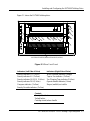
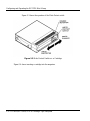
2-1 Drive Front Panel........................................................................................... 2-3
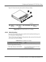
2-2 DLT4000 Rear Panel...................................................................................... 2-4
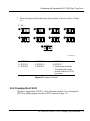
2-3 Changing the SCSI ID via the Pushbutton Switchpack ................................... 2-6
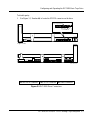
2-4 Rear Panel Components ................................................................................. 2-7
3-1 DLT4000 Drive Connectors ........................................................................... 3-3
3-2 SCSI ID Connector Pins................................................................................. 3-4
3-3 Jumper Positions ............................................................................................ 3-5
3-4 DLT4000 Jumper Setting for TRM PWR........................................................ 3-7
3-5 DLT4000 Rear Connectors............................................................................. 3-7
3-6 DLT4000 Indicators..................................................................................... 3-11
3-7 Tape Cartridge............................................................................................. 3-18
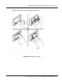
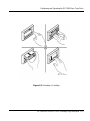
3-8 Loading a Cartridge ..................................................................................... 3-21
3-9 Unloading a Cartridge.................................................................................. 3-25
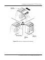
4-1 Front of the DLT4500 mini-library................................................................. 4-3
4-2 Mini-Library Rear Panel Components ............................................................ 4-4
4-3 Loosening the Shipping Screw ....................................................................... 4-5
4-4 Rotate the Locking Lever................................................................................ 4-6
4-5 Mini-Library Operator Control Panel ........................................................... 4-12
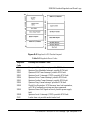
4-6 Normal Mode Field Definition ..................................................................... 4-14
4-8 Density Mode Field Definition ..................................................................... 4-16
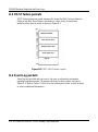
4-9 Firmware Update Mode Field Definition ...................................................... 4-19
4-10 Write-Protect Switch on a Cartridge........................................................... 4-25
4-11 DLT4500 Magazine ................................................................................... 4-26
4-12 Inserting a Cartridge into the Magazine ..................................................... 4-28
4-13 Removing a Cartridge from the Magazine.................................................. 4-29
5-1 Changing the SCSI ID via the Pushbutton Switch .......................................... 5-4

Contents
DLT4000\DLT4500\DLT4700 Cartridge Tape Subsystem-xvii
5-2 DLT4700 Operator Control Panel...................................................................5-6
5-3 Write-Protect Switch on a Cartridge............................................................. 5-22
5-4 Inserting a Cartridge into the Magazine........................................................ 5-23
5-5 Removing a Cartridge from the Front of the Magazine................................. 5-25
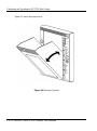
5-6 Receiver Opened........................................................................................... 5-26
6-1 Opening the Cartridge Door to Check the Tape Leader...................................6-4
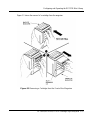
7-1 DLT4700 Subsystem Connectors....................................................................7-3
7-2 Jumper Settings for TRM PWR Connector .....................................................7-4
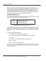
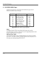
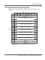
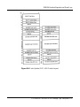
8-1 Extended Message Format............................................................................ 8-10
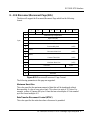
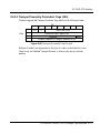
8-2 SDTR Extended Message Format ................................................................. 8-13
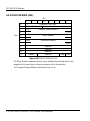
8-3 ERASE CDB................................................................................................ 8-16
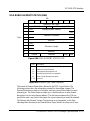
8-4 INQUIRY CDB............................................................................................ 8-17
8-5 INQUIRY Response Data............................................................................. 8-18
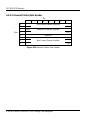
8-6 INQUIRY Vendor Unique Bytes Definition.................................................. 8-21
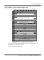
8-7 Supported Vital Product Data Pages ............................................................. 8-23
8-8 Unit Serial Number page.............................................................................. 8-23
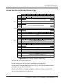
8-9 Firmware Build Information page................................................................. 8-24
8-10 LOAD-UNLOAD CDB ..............................................................................8-25
8-11 LOCATE CDB........................................................................................... 8-27
8-12 LOG SELECT CDB ................................................................................... 8-28
8-13 LOG Page Control Definitions.................................................................... 8-29
8-14 Clearable Log Pages ................................................................................... 8-30
8-15 Read/Write Error Log Select Page Format .................................................. 8-31
8-16 Parameter Codes Supported........................................................................ 8-33
8-17 LOG SENSED CDB................................................................................... 8-34
8-18 LOG Page Control Definitions.................................................................... 8-35
8-19 LOG SENSE Pages Supported.................................................................... 8-36
8-20 Supported Pages Page Format..................................................................... 8-37
8-21 Read/Write Error Log SENSE Page Format................................................ 8-38

Contents
xviii-DLT4000\DLT4500\DLT4700 Cartridge Tape Subsystem
8-22 Parameter Codes Supported........................................................................ 8-39
8-23 Threshold Met Criteria............................................................................... 8-40
8-24 Last n Error Events Page............................................................................ 8-41
8-25 Parameter Codes Supported........................................................................ 8-42
8-26 Read/Write Compression Ratio Page Header .............................................. 8-42
8-27 Read/Write Compression Ratio LOG SENSE Page Format......................... 8-43
8-28 Read/Write Bytes Transferred LOG SENSE Page Format........................... 8-44
8-29 MODE SELECT CDB................................................................................ 8-46
8-30 MODE SELECT Parameter List................................................................. 8-47
8-31 MODE SELECT Pages Supported.............................................................. 8-50
8-32 Error Recovery Page Format....................................................................... 8-51
8-33 Disconnect/Reconnect Page Format............................................................ 8-53
8-34 Data Transfer Disconnect Control .............................................................. 8-54
8-37 Control Mode Page (0Ah)........................................................................... 8-56
8-38 Data Compression Page.............................................................................. 8-58
8-35 Device Configuration Page Format............................................................. 8-60
8-36 Medium Partition Page Format................................................................... 8-63
8-39 EEROM Vendor Unique Page Format........................................................ 8-64
8-40 EEROM Vendor Unique Page Example 1................................................... 8-68
8-41 EEROM Vendor Unique Page Example 2................................................... 8-69
8-42 MODE SENSE CDB (6)............................................................................. 8-71
8-43 MODE SENSE CDB (10)........................................................................... 8-72
8-44 MODE SENSE Page Control Definition..................................................... 8-72
8-45 MODE SENSE (6) Data Header................................................................. 8-74
8-46 MODE SENSE (10) Data Header............................................................... 8-74
8-47 MODE SENSE Block Descriptor................................................................ 8-75
8-48 MODE SENSE Page Descriptor ................................................................. 8-75
8-49 MODE SENSE Pages Supported ................................................................ 8-78
8-50 Error Recovery Page Format....................................................................... 8-79
Page is loading ...
Page is loading ...
Page is loading ...
Page is loading ...
Page is loading ...
Page is loading ...
Page is loading ...
Page is loading ...
Page is loading ...
Page is loading ...
Page is loading ...
Page is loading ...
Page is loading ...
Page is loading ...
Page is loading ...
Page is loading ...
Page is loading ...
Page is loading ...
Page is loading ...
Page is loading ...
Page is loading ...
Page is loading ...
Page is loading ...
Page is loading ...
Page is loading ...
Page is loading ...
Page is loading ...
Page is loading ...
Page is loading ...
Page is loading ...
Page is loading ...
Page is loading ...
Page is loading ...
Page is loading ...
Page is loading ...
Page is loading ...
Page is loading ...
Page is loading ...
Page is loading ...
Page is loading ...
Page is loading ...
Page is loading ...
Page is loading ...
Page is loading ...
Page is loading ...
Page is loading ...
Page is loading ...
Page is loading ...
Page is loading ...
Page is loading ...
Page is loading ...
Page is loading ...
Page is loading ...
Page is loading ...
Page is loading ...
Page is loading ...
Page is loading ...
Page is loading ...
Page is loading ...
Page is loading ...
Page is loading ...
Page is loading ...
Page is loading ...
Page is loading ...
Page is loading ...
Page is loading ...
Page is loading ...
Page is loading ...
Page is loading ...
Page is loading ...
Page is loading ...
Page is loading ...
Page is loading ...
Page is loading ...
Page is loading ...
Page is loading ...
Page is loading ...
Page is loading ...
Page is loading ...
Page is loading ...
Page is loading ...
Page is loading ...
Page is loading ...
Page is loading ...
Page is loading ...
Page is loading ...
Page is loading ...
Page is loading ...
Page is loading ...
Page is loading ...
Page is loading ...
Page is loading ...
Page is loading ...
Page is loading ...
Page is loading ...
Page is loading ...
Page is loading ...
Page is loading ...
Page is loading ...
Page is loading ...
Page is loading ...
Page is loading ...
Page is loading ...
Page is loading ...
Page is loading ...
Page is loading ...
Page is loading ...
Page is loading ...
Page is loading ...
Page is loading ...
Page is loading ...
Page is loading ...
Page is loading ...
Page is loading ...
Page is loading ...
Page is loading ...
Page is loading ...
Page is loading ...
Page is loading ...
Page is loading ...
Page is loading ...
Page is loading ...
Page is loading ...
Page is loading ...
Page is loading ...
Page is loading ...
Page is loading ...
Page is loading ...
Page is loading ...
Page is loading ...
Page is loading ...
Page is loading ...
Page is loading ...
Page is loading ...
Page is loading ...
Page is loading ...
Page is loading ...
Page is loading ...
Page is loading ...
Page is loading ...
Page is loading ...
Page is loading ...
Page is loading ...
Page is loading ...
Page is loading ...
Page is loading ...
Page is loading ...
Page is loading ...
Page is loading ...
Page is loading ...
Page is loading ...
Page is loading ...
Page is loading ...
Page is loading ...
Page is loading ...
Page is loading ...
Page is loading ...
Page is loading ...
Page is loading ...
Page is loading ...
Page is loading ...
Page is loading ...
Page is loading ...
Page is loading ...
Page is loading ...
Page is loading ...
Page is loading ...
Page is loading ...
Page is loading ...
Page is loading ...
Page is loading ...
Page is loading ...
Page is loading ...
Page is loading ...
Page is loading ...
Page is loading ...
Page is loading ...
Page is loading ...
Page is loading ...
Page is loading ...
Page is loading ...
Page is loading ...
Page is loading ...
Page is loading ...
Page is loading ...
Page is loading ...
Page is loading ...
Page is loading ...
Page is loading ...
Page is loading ...
Page is loading ...
Page is loading ...
Page is loading ...
Page is loading ...
Page is loading ...
Page is loading ...
Page is loading ...
Page is loading ...
Page is loading ...
Page is loading ...
Page is loading ...
Page is loading ...
Page is loading ...
Page is loading ...
Page is loading ...
Page is loading ...
Page is loading ...
Page is loading ...
Page is loading ...
Page is loading ...
Page is loading ...
Page is loading ...
Page is loading ...
Page is loading ...
Page is loading ...
Page is loading ...
Page is loading ...
Page is loading ...
Page is loading ...
Page is loading ...
Page is loading ...
Page is loading ...
Page is loading ...
Page is loading ...
Page is loading ...
Page is loading ...
Page is loading ...
Page is loading ...
Page is loading ...
Page is loading ...
Page is loading ...
Page is loading ...
Page is loading ...
Page is loading ...
Page is loading ...
Page is loading ...
Page is loading ...
Page is loading ...
Page is loading ...
Page is loading ...
Page is loading ...
Page is loading ...
Page is loading ...
Page is loading ...
Page is loading ...
Page is loading ...
Page is loading ...
Page is loading ...
Page is loading ...
Page is loading ...
Page is loading ...
Page is loading ...
Page is loading ...
Page is loading ...
Page is loading ...
Page is loading ...
Page is loading ...
Page is loading ...
Page is loading ...
Page is loading ...
Page is loading ...
Page is loading ...
Page is loading ...
Page is loading ...
Page is loading ...
Page is loading ...
Page is loading ...
Page is loading ...
Page is loading ...
Page is loading ...
Page is loading ...
Page is loading ...
Page is loading ...
Page is loading ...
Page is loading ...
Page is loading ...
Page is loading ...
Page is loading ...
Page is loading ...
Page is loading ...
Page is loading ...
Page is loading ...
Page is loading ...
Page is loading ...
Page is loading ...
Page is loading ...
Page is loading ...
Page is loading ...
Page is loading ...
Page is loading ...
Page is loading ...
Page is loading ...
Page is loading ...
Page is loading ...
Page is loading ...
Page is loading ...
Page is loading ...
Page is loading ...
Page is loading ...
Page is loading ...
Page is loading ...
Page is loading ...
Page is loading ...
Page is loading ...
Page is loading ...
Page is loading ...
Page is loading ...
Page is loading ...
Page is loading ...
Page is loading ...
Page is loading ...
Page is loading ...
Page is loading ...
Page is loading ...
Page is loading ...
Page is loading ...
Page is loading ...
Page is loading ...
Page is loading ...
Page is loading ...
Page is loading ...
Page is loading ...
Page is loading ...
Page is loading ...
Page is loading ...
Page is loading ...
Page is loading ...
Page is loading ...
Page is loading ...
Page is loading ...
Page is loading ...
Page is loading ...
Page is loading ...
Page is loading ...
Page is loading ...
Page is loading ...
Page is loading ...
Page is loading ...
Page is loading ...
Page is loading ...
-
 1
1
-
 2
2
-
 3
3
-
 4
4
-
 5
5
-
 6
6
-
 7
7
-
 8
8
-
 9
9
-
 10
10
-
 11
11
-
 12
12
-
 13
13
-
 14
14
-
 15
15
-
 16
16
-
 17
17
-
 18
18
-
 19
19
-
 20
20
-
 21
21
-
 22
22
-
 23
23
-
 24
24
-
 25
25
-
 26
26
-
 27
27
-
 28
28
-
 29
29
-
 30
30
-
 31
31
-
 32
32
-
 33
33
-
 34
34
-
 35
35
-
 36
36
-
 37
37
-
 38
38
-
 39
39
-
 40
40
-
 41
41
-
 42
42
-
 43
43
-
 44
44
-
 45
45
-
 46
46
-
 47
47
-
 48
48
-
 49
49
-
 50
50
-
 51
51
-
 52
52
-
 53
53
-
 54
54
-
 55
55
-
 56
56
-
 57
57
-
 58
58
-
 59
59
-
 60
60
-
 61
61
-
 62
62
-
 63
63
-
 64
64
-
 65
65
-
 66
66
-
 67
67
-
 68
68
-
 69
69
-
 70
70
-
 71
71
-
 72
72
-
 73
73
-
 74
74
-
 75
75
-
 76
76
-
 77
77
-
 78
78
-
 79
79
-
 80
80
-
 81
81
-
 82
82
-
 83
83
-
 84
84
-
 85
85
-
 86
86
-
 87
87
-
 88
88
-
 89
89
-
 90
90
-
 91
91
-
 92
92
-
 93
93
-
 94
94
-
 95
95
-
 96
96
-
 97
97
-
 98
98
-
 99
99
-
 100
100
-
 101
101
-
 102
102
-
 103
103
-
 104
104
-
 105
105
-
 106
106
-
 107
107
-
 108
108
-
 109
109
-
 110
110
-
 111
111
-
 112
112
-
 113
113
-
 114
114
-
 115
115
-
 116
116
-
 117
117
-
 118
118
-
 119
119
-
 120
120
-
 121
121
-
 122
122
-
 123
123
-
 124
124
-
 125
125
-
 126
126
-
 127
127
-
 128
128
-
 129
129
-
 130
130
-
 131
131
-
 132
132
-
 133
133
-
 134
134
-
 135
135
-
 136
136
-
 137
137
-
 138
138
-
 139
139
-
 140
140
-
 141
141
-
 142
142
-
 143
143
-
 144
144
-
 145
145
-
 146
146
-
 147
147
-
 148
148
-
 149
149
-
 150
150
-
 151
151
-
 152
152
-
 153
153
-
 154
154
-
 155
155
-
 156
156
-
 157
157
-
 158
158
-
 159
159
-
 160
160
-
 161
161
-
 162
162
-
 163
163
-
 164
164
-
 165
165
-
 166
166
-
 167
167
-
 168
168
-
 169
169
-
 170
170
-
 171
171
-
 172
172
-
 173
173
-
 174
174
-
 175
175
-
 176
176
-
 177
177
-
 178
178
-
 179
179
-
 180
180
-
 181
181
-
 182
182
-
 183
183
-
 184
184
-
 185
185
-
 186
186
-
 187
187
-
 188
188
-
 189
189
-
 190
190
-
 191
191
-
 192
192
-
 193
193
-
 194
194
-
 195
195
-
 196
196
-
 197
197
-
 198
198
-
 199
199
-
 200
200
-
 201
201
-
 202
202
-
 203
203
-
 204
204
-
 205
205
-
 206
206
-
 207
207
-
 208
208
-
 209
209
-
 210
210
-
 211
211
-
 212
212
-
 213
213
-
 214
214
-
 215
215
-
 216
216
-
 217
217
-
 218
218
-
 219
219
-
 220
220
-
 221
221
-
 222
222
-
 223
223
-
 224
224
-
 225
225
-
 226
226
-
 227
227
-
 228
228
-
 229
229
-
 230
230
-
 231
231
-
 232
232
-
 233
233
-
 234
234
-
 235
235
-
 236
236
-
 237
237
-
 238
238
-
 239
239
-
 240
240
-
 241
241
-
 242
242
-
 243
243
-
 244
244
-
 245
245
-
 246
246
-
 247
247
-
 248
248
-
 249
249
-
 250
250
-
 251
251
-
 252
252
-
 253
253
-
 254
254
-
 255
255
-
 256
256
-
 257
257
-
 258
258
-
 259
259
-
 260
260
-
 261
261
-
 262
262
-
 263
263
-
 264
264
-
 265
265
-
 266
266
-
 267
267
-
 268
268
-
 269
269
-
 270
270
-
 271
271
-
 272
272
-
 273
273
-
 274
274
-
 275
275
-
 276
276
-
 277
277
-
 278
278
-
 279
279
-
 280
280
-
 281
281
-
 282
282
-
 283
283
-
 284
284
-
 285
285
-
 286
286
-
 287
287
-
 288
288
-
 289
289
-
 290
290
-
 291
291
-
 292
292
-
 293
293
-
 294
294
-
 295
295
-
 296
296
-
 297
297
-
 298
298
-
 299
299
-
 300
300
-
 301
301
-
 302
302
-
 303
303
-
 304
304
-
 305
305
-
 306
306
-
 307
307
-
 308
308
-
 309
309
-
 310
310
-
 311
311
-
 312
312
-
 313
313
-
 314
314
-
 315
315
-
 316
316
-
 317
317
-
 318
318
-
 319
319
-
 320
320
-
 321
321
-
 322
322
-
 323
323
-
 324
324
-
 325
325
-
 326
326
-
 327
327
-
 328
328
-
 329
329
-
 330
330
-
 331
331
-
 332
332
-
 333
333
-
 334
334
-
 335
335
-
 336
336
-
 337
337
-
 338
338
-
 339
339
-
 340
340
-
 341
341
-
 342
342
-
 343
343
-
 344
344
-
 345
345
-
 346
346
-
 347
347
-
 348
348
-
 349
349
-
 350
350
-
 351
351
-
 352
352
-
 353
353
-
 354
354
-
 355
355
-
 356
356
-
 357
357
-
 358
358
-
 359
359
-
 360
360


Ask a question and I''ll find the answer in the document
Finding information in a document is now easier with AI
Related papers
-
Quantum Scalar i2000 User guide
-
-
-
-
Quantum DLT-S4 Reference guide
-
-
-
-
-
Other documents
-
HP 220mx Reference guide
-
 ADIC 4000 User manual
-
Fujitsu M2488 User manual
-
 ADIC FastStor Mass Storage Device User manual
-
BEL PEC800 (DC-DC Intel Standard CRPS) Owner's manual
-
 ADIC Scalar Series User manual
-
 Ciprico Rimfire 3880 User manual
-
Moxa EOM-104 Series User manual
-
Bull Escala EPC Series - Rack Service guide
-
Broadcom scounix User guide


