Page is loading ...

USER’S GUIDE
Lab Source Manual
Models LS-1 and LS-2
1791 Deere Avenue • Irvine, CA 92606 • USA
phone: (949) 863-3144 • fax: (949) 253-1680
e-mail:[email protected] • www.newport.com

2
Declaration of Conformity
We declare that the accompanying product, identified with the mark,
complies with requirements of the Electromagnetic Compatibility
Directive, 2004/108/EC and the Low Voltage Directive 2006/95/EC.
Model Numbers: LSx Series
Year mark affixed: 2013
Type of Equipment: Electrical equipment for measurement, control
and laboratory use in industrial locations.
Manufacturer: PD-LD, Inc.
30-B Pennington-Hopewell Road
Pennington, NJ 08534
United States of America
Importer: Newport Corporation
1791 Deere Avenue
Irvine, CA 92606
United States of America
Standards Applied:
Compliance was demonstrated to the following standards to the
extent applicable:
BS EN61326-1: 2006 “Electrical equipment for measurement, control
and laboratory use – EMC requirements” (Laboratory)
This equipment meets the CISPR 11:2009+A1:2010 Class A Group 1
radiated and conducted emission limits.
BS EN 61010-1:2010, “Safety requirements for electrical equipment for
measurement, control and laboratory use”.
Mark Carroll
Sr. Director, Instruments Business
Newport Corporation
1791 Deere Ave, Irvine, CA 92606 USA
Uri Abrams
President
PD-LD, Inc.
30-B Pennington-Hopewell Road
Pennington, NJ 08534 USA

3
Warranty
Newport warrants that this product will be free from defects in material
and workmanship and will comply with Newport’s published
specifications at the time of sale for a period of one year from date of
shipment. If found to be defective during the warranty period, the
product will either be repaired or replaced at Newport’s option.
To exercise this warranty, write or call your local Newport office or
representative, or contact Newport headquarters in Irvine, California.
You will be given prompt assistance and return instructions. Send the
product, freight prepaid, to the indicated service facility. Repairs will
be made and the instrument returned freight prepaid. Repaired
products are warranted for the remainder of the original warranty
period or 90 days, whichever first occurs.
Limitation of Warranty
The above warranties do not apply to products which have been
repaired or modified without Newport’s written approval, or products
subjected to unusual physical, thermal or electrical stress, improper
installation, misuse, abuse, accident or negligence in use, storage,
transportation or handling. This warranty also does not apply to
fuses, batteries, or damage from battery leakage.
THIS WARRANTY IS IN LIEU OF ALL OTHER WARRANTIES,
EXPRESSED OR IMPLIED, INCLUDING ANY IMPLIED WARRANTY OF
MERCHANTABILITY OR FITNESS FOR A PARTICULAR USE.
NEWPORT SHALL NOT BE LIABLE FOR ANY INDIRECT, SPECIAL, OR
CONSEQUENTIAL DAMAGES RESULTING FROM THE PURCHASE
OR USE OF ITS PRODUCTS.
First printing 2014
© 2014 by Newport, Irvine, CA. All rights reserved. No part of this
manual may be reproduced or copied without the prior written
approval of Newport. This manual has been provided for information
only and product specifications are subject to change without notice.
Any change will be reflected in future printings.
Newport
1791 Deere Avenue
Irvine, CA, 92606 USA
Part No. 90059942 Rev A

4
Confidentiality & Proprietary Rights
Reservation of Title
The Newport programs and all materials furnished or produced in
connection with them (“Related Materials”) contain trade secrets of
Newport and are for use only in the manner expressly permitted.
Newport claims and reserves all rights and benefits afforded under
law in the Programs provided by Newport.
Newport shall retain full ownership of Intellectual Property Rights in
and to all development, process, align or assembly technologies
developed and other derivative work that may be developed by
Newport. Customer shall not challenge, or cause any third party to
challenge the rights of Newport.
Preservation of Secrecy and Confidentiality and Restrictions to Access
Customer shall protect the Newport Programs and Related Materials
as trade secrets of Newport, and shall devote its best efforts to ensure
that all its personnel protect the Newport Programs as trade secrets of
Newport. Customer shall not at any time disclose Newport’s trade
secrets to any other person, firm, organization, or employee that does
not need (consistent with Customer’s right of use hereunder) to obtain
access to the Newport Programs and Related Materials. These
restrictions shall not apply to information (1) generally known to the
public or obtainable from public sources; (2) readily apparent from the
keyboard operations, visual display, or output reports of the Programs;
3) previously in the possession of Customer or subsequently
developed or acquired without reliance on the Newport Programs; or
(4) approved by Newport for release without restriction.
Trademarks
The Newport logo and name are registered trademarks of Newport
Corporation in Mexico, Israel, Singapore, European Union, Taiwan, Hong
Kong, China, Japan, Korea, Canada, Australia, and the United States.
Service Information
This section contains information regarding factory service for the
source. The user should not attempt any maintenance or service of
the system or optional equipment beyond the procedures outlined in
this manual. Any problem that cannot be resolved should be referred
to Newport.

5
Technical Support Contacts
Newport Corporation Calling Procedure
If there are any defects in material or workmanship or a failure to meet
specifications, promptly notify Newport’s Returns Department by
calling 1-800-222-6440 or by visiting our website at www.newport.
com/returns within the warranty period to obtain a Return Material
Authorization Number (RMA#). Return the product to Newport
Corporation, freight prepaid, clearly marked with the RMA# and we
will either repair or replace it at our discretion. Newport is not
responsible for damage occurring in transit and is not obligated to
accept products returned without an RMA#.
E-mail: [email protected]
When calling Newport Corporation, please provide the customer care
representative with the following information:
Your Contact Information
Serial number or original order number
Description of problem (i.e., hardware or software)
To help our Technical Support Representatives diagnose your
problem, please note the following conditions:
Is the system used for manufacturing or research and development?
What was the state of the system right before the problem?
Have you seen this problem before? If so, how often?
Can the system continue to operate with this problem? Or is the
system non-operational?
Can you identify anything that was different before this problem
occurred?
North America
Newport
1791 Deere Avenue
Irvine, CA 92606
Telephone: (877) 835-9620
Europe
Newport/MICRO-CONTROLE S.A.
Zone Industrielle
45340 Beaune la Rolande, FRANCE
Telephone: (33) 02 38 40 51 56
Asia
Newport Opto-Electronics Technologies
中国 上海市 爱都路 253号 第3号楼 3层 C部位, 邮编 200131
253 Aidu Road, Bld #3, Flr 3, Sec C, Shanghai 200131, China
Telephone: +86-21-5046 2300
Fax: +86-21-5046 2323

6
Contents
Preface 10
Important Symbols
Used in this Manual 10
1. Safety 11
1.1 Laser Safety Precautions . . . . . . . . . . . 11
1.2 Optical Safety . . . . . . . . . . . . . . . . . . . . 12
1.3 EMC Considerations . . . . . . . . . . . . . . 14
2. Description 15
3. Key Performance Features 15
4. Specifications 16
5. Performance Data 18
6. Mechanical Dimensions 20
7. Handling and Installation 20
7.1 Optical Connection . . . . . . . . . . . . . . . 20
7.2 Thermal Considerations . . . . . . . . . . . 21
7.3 Operation . . . . . . . . . . . . . . . . . . . . . . . 21
7.3.1 Using The Lab Source . . . . . . . . . . . . 21
8. User Interface 22
8.1 LED Indicators . . . . . . . . . . . . . . . . . . . 22
8.2 Front Panel Menu and Key Operation
for LS-1 . . . . . . . . . . . . . . . . . . . . . . . . . . . . . . . . 22
8.3 Front Panel Menu and Key Operation
for LS-2 . . . . . . . . . . . . . . . . . . . . . . . . . . . . 22

7
8.4 The Main Screen . . . . . . . . . . . . . . . . . . 23
8.5 Selecting APC or ACC Mode . . . . . . . . 23
8.5.1 APC (Automatic Power Control)
Mode . . . . . . . . . . . . . . . . . . . . . . . . . . . . . . 23
8.5.2 ACC (Automatic Current Control)
Mode . . . . . . . . . . . . . . . . . . . . . . . . . . . . . . 23
8.6 Shutter Time . . . . . . . . . . . . . . . . . . . . . 24
8.7 Analog Input . . . . . . . . . . . . . . . . . . . . . 24
8.8 Modulation Input . . . . . . . . . . . . . . . . . 24
8.9 Shutter Input . . . . . . . . . . . . . . . . . . . . 25
8.10 Laser On / Off . . . . . . . . . . . . . . . . . . . 25
8.11 I-Lock . . . . . . . . . . . . . . . . . . . . . . . . . 25
8.12 Power Button . . . . . . . . . . . . . . . . . . . 25
8.13 Emergency Stop Button . . . . . . . . . . 26
8.14 Key Lock Switch . . . . . . . . . . . . . . . . . 26
8.15 Alarms . . . . . . . . . . . . . . . . . . . . . . . . . 26
8.16 Troubleshooting . . . . . . . . . . . . . . . . . 28
9. Lab Source Control Panel Software 29
9.1 System Requirements . . . . . . . . . . . . . 29
9.2 Installing the USB Driver . . . . . . . . . . . 29
9.3 Installing the Lab Source
Control Panel . . . . . . . . . . . . . . . . . . . . . . . 30
9.4 Determining the Proper Com Port
for the Lab Source Control Panel . . . . . . . 30
9.5 Lab Source Control Panel and Initial
Setup. . . . . . . . . . . . . . . . . . . . . . . . . . . . . . 31
9.6 Lab Source Control Panel Functions . 32
9.7 Lab Source Firmware Updates . . . . . . 32
9.8 Control Panel Software Update. . . . . . 32

8
10. Communications Protocol 33
10.1 Port Settings . . . . . . . . . . . . . . . . . . . . 33
10.2 Initialize Message and Link Status . 33
10.3 Command Sequence . . . . . . . . . . . . 33
10.4 Receiving Data . . . . . . . . . . . . . . . . . . 34
10.5 Error Messages . . . . . . . . . . . . . . . . . 34
10.6 Monitoring Commands . . . . . . . . . . 34
10.7 Setting Commands . . . . . . . . . . . . . . 38
10. mmand: SST<><XXXXXX><CR> . . . . 41
11. Maintenance and Service 42
11.1 Enclosure Cleaning . . . . . . . . . . . . . . 42
11.2 Technical Support . . . . . . . . . . . . . . . 42
11.3 Service . . . . . . . . . . . . . . . . . . . . . . . . 43
11.4 Obtaining Service . . . . . . . . . . . . . . . . 43
11.5 Warranty . . . . . . . . . . . . . . . . . . . . . . . 43
11.6 Service Form . . . . . . . . . . . . . . . . . . . 44

9
Important Symbols
Used in this Manual
This manual contains user information for Newport
Corporation’s LS1 and LS2 Lab Source modules.
The single-source LS1 is a laboratory instrument
designed for Raman spectroscopy and other
applications requiring the use of a highly stabilized
laser, while the dual-source LS2 module’s
applications include Surface Enhanced Raman
Differential Spectroscopy (SERDS) analysis.
This symbol is used to alert the operator to the
presence of dangerous voltages associated with the
laser that may be of sufficient magnitude to
constitute a risk of electric shock.
This symbol is used to alert the operator to the
danger of exposure to hazardous visible or infrared
(invisible) laser radiation.
This symbol is used to show cautions or important
operating instructions.
Performing any procedures other than those
specified in this manual may result in hazardous
radiation exposure.
Preface

10
This symbol on the product or on its packaging
indicates that this product must not be disposed of
with regular waste. Instead, it is the user
responsibility to dispose of waste equipment
according to the local laws. The separate collection
and recycling of the waste equipment at the time of
disposal will help to conserve natural resources and
ensure that it is recycled in a manner that protects
human health and the environment. For
information about where the user can drop off the
waste equipment for recycling, please contact your
local Newport Corporation representative.
The presence of the CE Mark on a product means
that this instrument has been designed, tested and
certified compliant to all applicable European
Union (CE) regulations and recommendations.
Embedded lasers emit Class IV radiation. Extreme
care should be exercised during operation. Only
personnel familiar with the safety precautions and
practices in this manual should operate the laser
products.
Embedded lasers are Class IV laser products.
Average powers exceeding 500mW are obtainable
with the Lab Source devices. Always wear proper
eye protection when operating.
Laser safety glasses can present a hazard as well as a
benefit: while they protect the eye from potentially
damaging exposure, they block light at the laser
wavelength, which prevents the operator from seeing
the beam. Therefore, use extreme caution even when
using safety glasses.
1. Safety
1.1 Laser Safety Precautions

11
Avoid eye or skin exposure to direct or scattered
radiation from the laser.
Personnel operating these laser products should be
familiar with and follow the recommendations
given below and in this manual:
1.
Always wear laser safety eyewear, which is
optically dense at the wavelength of opera-
tion per site Laser Safety Officer calculation.
2. Never look directly into the beam or at specu-
lar reflections even while wearing protective
eyewear.
3. Use safety interlocks to restrict access to laser
areas and prevent unauthorized use of the
lasers.
4. Post warning signs for Class IV laser products.
5. Do not subject any body parts to direct
radiation.
Laser light, because of its special properties, poses
safety hazards not associated with light from
conventional sources. The safe use of lasers
requires that all laser users, and everyone near the
laser system, are aware of the dangers involved. The
safe use of the laser depends upon the user being
familiar with the instrument and the properties of
coherent, intense beams of light.
Direct eye contact with the output beam from the
laser will cause serious eye damage and possible
blindness.
The greatest concern when using a laser is eye
safety. In addition to the main beam, there are
often smaller beams present at various angles near
the laser system. These beams are formed by
specular reflections of the main beam at polished
surfaces such as lenses or beam splitters. While
1.2 Optical Safety

12
weaker than the main beam, such beams may still
be sufficiently intense to cause eye damage to nerve
or blood vessels.
Laser beams often are powerful enough to burn
skin, clothing or paint. They can ignite volatile
substances such as alcohol, gasoline, ether and
other solvents, and can damage light-sensitive
elements in video cameras, photo-multipliers and
photodiodes. The laser beam can ignite substances
in its path, even at some distances. The beam may
also cause damage if contacted indirectly from
reflective surfaces. For these reasons, and others,
the user is advised to follow the precautions below
and in this manual.
1.
Observe all safety precautions in this manual.
2. Extreme caution should be exercised when
using solvents in the area of the laser.
3. Limit access to the laser to qualified users who
are familiar with laser safety practices and who
are aware of the dangers involved.
4. Never look directly into the laser light source
or at scattered laser light from any reflective
surface. Never sight down the beam into source.
5. Maintain experimental setups at low heights
to prevent inadvertent beam-eye encounter at
eye level.
6. As a precaution against accidental exposure to
the output beam or its reflection, those using
the system should wear laser safety glasses as
required by the wavelength being generated.
7. Avoid direct exposure to the laser light. The
intensity of the beam can easily cause flesh
burns or ignite clothing.
8. Use the laser in an enclosed room. Laser light
presents a potential hazard if not confined.

13
9. Post warning signs in the area of the laser
beam to alert those present.
10. Advise all those using the laser of these pre-
cautions. It is good practice to operate the laser
in a room with controlled and restricted access.
Performing any procedures other than those
specified in this manual may result in hazardous
radiation exposure.
Notice that main disconnect is removing the power
cord.
Position the product so you have access to main
power cord.
Do not replace the detachable MAINs supply cord
with an inadequately rated cord.
If equipment is used in a manner not specified by
the manufacturer, the protection provided by the
equipment may be impaired.
The LS-1 and LS-2 products are intended for use in
an industrial laboratory environment. Use of these
products in other environments, such as
residential, may result in electromagnetic
compatibility difficulties due to conducted as well
as radiated disturbances.
The LS-1 and LS-2 products are designed to operate
in a controlled electromagnetic environment; i.e.,
where R.F. transmitters such as mobile telephones
may not be used in close proximity.
1.3 Warnings
1.4 EMC Considerations

14
Lab Source is the optimum solution for accurate,
sure detection of Raman spectra in ultra-sensitive
measurement systems. Based on highly stable and
proprietary Volume Bragg Grating® (VBG™)
technology, Lab Source is a convenient,
narrowband, stable high-power laser light source
ideally suited for Raman spectroscopy. When
configured with a pair of Shifted Excitation Raman
Difference Spectroscopy (SERDS) lasers, Lab Source
helps to eliminate fluorescence background. This
provides the user with unsurpassed signal-to-noise
performance without a need for costly tunable
lasers. Utilize Lab Source for Shifted Excitation
Raman Difference Spectroscopy (SERDS) and realize
the power and sensitivity that can be achieved.
• High power lasers, up to 1 Watt
• Narrow line width, < 0.1 nm
• SERDS option available
• Excellent wavelength stability, +/- 0.005 nm
• Excellent power stability, +/- 0.5 %
• Easy laser modulation, safe operation
• Front panel display
2. Description
3. Key Performance Features

15
4. Specifications
4.1 Optical Characteristics
Comments
Standard Wavelengths (nm) 647 785 830 1064 Multimode lasers
SERDS pairs available Ye s Ye s Ye s
SERDS pair (λ2 – λ1) (nm) 0.1 – 1.0 Custom adjustable
Center λ tolerance (nm) +/- 0.5
Wavelength stability (nm) +/- 0.005 Over 8 hours
Line width (nm) Typical 0.08; max. 0.15
Line width (cm-1) Typical 1.3; max. 2.4
ASE suppression (dB) >40
4.3 General and Environmental Characteristics
CDHR classification Class IV
Operating temperature C 10 – 40 LS1 (10-35 LS2)
Storage temperature C -10 – 60
Humidity no condensing % < 95
Environment Indoor Use Only
Interfaces USB 2.0, BNC
Altitude Below 2000 meters
Pollution Degree 2
4.2 Power / Electrical Characteristics
Comments
Output from fiber (mw)
>500 >600 >600
>800
Multimode lasers
Adjustability % full power 10 - 100
ACC Adjustment Resolution 1mA
APC Adjustment Resolution 5mW
Output power stability % +/- 0.5 Over 8 hours
Noise RMS % < 0.25
Noise P – P % < 1
Digital modulation 10 kHz (ACC Mode)
Analog modulation 10 Hz (ACC Mode)
Power consumption (W) 30
Warm up time (min) 1

16
4.4 Mechanical Characteristics
Comments
Dimensions (mm) 84 x 174 x 190
Weight (g) ~1200 to 1500 Varies per
version
Display size (mm) 58 x 12
4.5 Output Fiber Characteristics
Comments
Fiber type 105 um core; 0.22 NA Other available
Connector type FC/PC standard Other available
4.7 Optical Shutter Characteristics
Comments
Switching time (ms) < 10
Crosstalk (dB) < - 55
4.6 Electrical Characteristics
Comments
Line Voltage 100-240 VAC 50/60Hz
The Lab Source’s internal
120/240VAC power
supply can be used in
both North American and
International applications.
AC Mains 0.5 A
Analog Input 0-5V
Modulation Input 5V Logic Level
Shutter Input 5V Logic Level

17
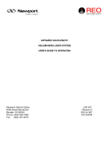
5. Performance Data
Relative Power (dB)
Wavelength (nm)
Laser 1
Laser 2
10
0
-10
-20
-30
-40
-50
780 781 782 783 784 785 786 787 788 789 790
Wavelength shift (nm)
Time (hh:mm)
0.03
0.02
0.01
0
-0.01
-0.02
-0.03
0:00 1:00 2:00 3:00 4:00 5:00 6:00 7:00 8:00 9:00 12:0011:0010:00
Example of a SERDS Laser Pair:
Center Wavelength Separation 1nm
Wavelength Drift Over 12 Hours

18
Power Drfit (%)
Time (hh:mm)
2.0
1.5
1.0
0.5
0
-0.5
-1.0
-1.5
-2.0
0:00 1:00 2:00 3:00 4:00 5:00 6:00 7:00 8:00 9:00 12:0011:0010:00
Power (mW)
Time (hh:mm)
600
500
400
300
200
100
0
0 5 10 15 20 25 30
Power Stability Over 12 Hours
Power Stabilization From Cold Start

19
The fiber end face must be free of debris. The
presence of debris on the fiber end face will cause
potential permanent damage to the end face
resulting in loss of optical performance.
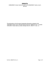
6. Mechanical Dimensions
7. Handling and Installation
7.1 Optical Connection
If fiber coupled, use a fiber jumper that has the
same core size as the Lab Source. Standard fiber
is 105/125 0.22NA multimode fiber with FC/APC
connector. The other end of the fiber can have
any appropriate connector suitable for required
operation (preferably with an angle polish).
Dimensions (mm / inch)
Height: 84 / 3.30
Width: 174 / 6.85
Depth: 190 / 7.45
1. Warning
2. Radiation statement
3. Invisible laser radiation,
safety Information
4. “Do not operate without
fiber connected”
5. Laser emission indicator
6. Emergency stop button
7. Laser danger warning
8. Laser aperture
9. WEEE Symbol
10. Model ID Label
1 2 3
5 6
7
4
8
9
10

20
When connecting the Lab Source using an external
fiber connector, ensure that:
• The Lab Source is turned off before the fiber
connector is attached.
• The end face of the ferrule is clean and free of
debris & solvents.
• The end face must be cleaned using industry
standard methods before each mating.
• No mechanical pressure is applied to the
window of free space units.
The Lab Source configuration may be accessed by
using the front panel keys, the provided PC
application, or through commands issued from
windows terminal, or your OEM software system.
• Connect the Lab Source to the fiber probe.
• Apply power to the Lab Source. Switch key-lock
to “on” position and press the power button.
• The Lab Source will power up and operate using
the settings that were last used.
• By default both lasers are turned off. Power on
each laser as desired.
• To change the settings access the menu (steps
in sections 9.2 and 9.3) or using the Lab Source
Control Panel Software (steps in section 10).
7.3 Operation
7.3.1 Using The Lab Source
The Lab Source uses internal fans to ensure
proper thermal control and reliability. The vents
under the front bottom and the rear fan must
remain UNOBSTRUCTED or permanent damage
to the Lab Source may result
7.2 Thermal Considerations
/