GE MDS 05-4558A01 User manual
- Category
- Television antennas
- Type
- User manual
This manual is also suitable for

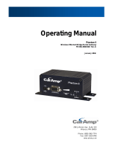
Start-Up Guide
Wireless IP/Ethernet Transceiver
Covering all AP and Remote Units
including Mercury 900, 3650, and Option Set 1 Remotes
MDS 05-4558A01, Rev. C
December 2008
MDS Mercury
™
Series

05-4558A01, Rev. C MDS Mercury Series Startup Guide
1
Contents
PRODUCT DESCRIPTION .....................................................2
INSTALLATION OVERVIEW ...................................................2
INSTALLATION STEPS ..........................................................2
Step 1—Mount the Transceiver ...................................................3
Step 2—Install the Antenna ........................................................3
Step 3—Measure & Connect Primary Power ..............................4
Step 4—Review the Transceiver’s Configuration ........................4
Step 5—Connect the Data Equipment ........................................7
Step 6—Check for Normal Operation .........................................7
Resetting to Factory Defaults (Use with Care) ............................8
AIMING DIRECTIONAL ANTENNAS .....................................8
Procedure ...................................................................................9
TRANSMITTER POWER AND ANTENNA TEST .................10
Procedure .................................................................................10
TROUBLESHOOTING ..........................................................11
SPECIFICATIONS ................................................................14
TECHNICAL ASSISTANCE ..................................................16
FACTORY SERVICE .............................................................16
Copyright Notice
This publication is protected by U.S.A. copyright law. Copyright 2008, GE MDS. All
rights reserved.
The center of this guide contains a chart with a summary of installation
procedures. Refer to the Mercury Reference Manual (05-4446A01) for
additional warnings, cautions, and notes.

2 MDS Mercury Series Startup Guide 05-4558A01, Rev. C
PRODUCT DESCRIPTION
MDS Mercury
TM
Series transceivers provide an easy-to-install wire-
less network service with long range and secure operation at adaptive
data rates approaching 12 Mbps. The transceiver is ideally suited for
demanding applications in mobile or fixed environments, where reli-
ability and range are paramount.
The product is commonly used to send text documents, graphics,
email, video, voice over IP (VoIP), and a variety of other application
data between mobile, fixed-point, and LAN-based entities.
The transceiver comes in two primary models—Access Point and
Remote, each with unique hardware profiles. Both models support
Ethernet and serial services. An Access Point (AP) is a wireless hub
that usually provides connectivity into a wired Ethernet LAN/WAN.
Remotes associate over the air with an Access Point and are typically
connected to an Ethernet or Serial device via a cable.
INSTALLATION OVERVIEW
There are three main requirements for installing the transceiver—ade-
quate and stable primary power, a good antenna system, and the cor-
rect interface between the transceiver and the data device. The
Installation Setup Chart (center of this guide) shows a typical Remote
installation. Access Point and mobile Remote stations typically use
omnidirectional antennas whereas fixed-site Remotes typically use
directional antennas such as a Yagi or panel type. Otherwise, both
installations are similar.
INSTALLATION STEPS
A typical shipment consists of a transceiver, a power connector and
this start-up guide. Below are the basic steps for installing a trans-
ceiver. Refer to the
Mercury Reference Manual
for detailed informa-
tion. You will also find support information at the GE MDS Web site:
www.GEmds.com. Our Technical Services Team is available to assist
with any difficulties that may be encountered. Refer to the back of this
guide for contact information.
It is highly recommended that the Access Point unit be installed
first
so that
you can quickly check the operation of each associated Remote
as it is placed on the air.

05-4558A01, Rev. C MDS Mercury Series Startup Guide
3
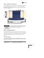
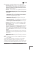
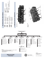
Step 1—Mount the Transceiver
Use the supplied 6-32 x 1/4 inch (6 mm) screws to attach the mounting
brackets to the bottom of the radio. Figure 1 shows the mounting
dimensions of the unit. Mount the radio to a stable surface. (Fasteners
not normally supplied.)
Invisible place holder
Figure 1. Transceiver Mounting Dimensions
(Dimensions for AP and Remotes identical)
Use only the supplied mounting bracket screws. Screws
extending farther than 1/4 inch (6 mm) into the case
may cause internal PC board damage.
Step 2—Install the Antenna
To minimize RF interference, the antenna should be mounted at least
nine inches (> 23 cm) from the connected device(s), sensors and other
external components of the system. Additional information on antenna
selection and installation is provided in the
Mercury Reference
Manual
.
Install GPS Antenna
Install the GPS antenna in accordance with the manufacturer’s instruc-
tions, and connect the antenna cable to the SMB-type connector on the
transceiver’s front panel.
2.75˝ (7 cm)
8 5/8˝ (21.8 cm)
CAUTION
POSSIBLE
EQUIPMENT
DAMAGE

4 MDS Mercury Series Startup Guide 05-4558A01, Rev. C
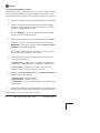
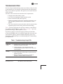
Step 3—Measure & Connect Primary Power
The DC input power to the transceiver must be within 10–30 Vdc and
capable of continuously providing at least 2.5 Amperes. A power con-
nector with screw-terminals is provided with each unit. Strip the wire
leads to 6 mm (1/4 inch). Be sure to observe proper polarity as shown
in Figure 2 with the positive lead (
+
) on the left side; negative on the
right side.
Invisible place holder
Figure 2. Power Connector
(Polarity: Left +, Right –)
The transceiver must be used with negative-ground sys-
tems only. The power supply should be equipped with
overload protection (NEC Class 2 rating), to protect
against a short circuit between its output terminals and
the radio’s power connector.
NOTE:
Typically, it takes about 30 seconds for the transceiver to fully
power up, and may take several minutes to associate with
another unit, especially if GPS is required for time synchroni-
zation.
Step 4—Review the Transceiver’s Configuration
There are two key settings that must be known before placing the unit
into service:
•
Network Name
—
Common identifier used by all of the units, that
are part of the same network. The Network Name must be pro-
grammed to enable Remote units to associate with the Access
Point unit. (Default name is
MDS-Mercury
.)
•
IP Address
—Must be a unique address to allow for IP access
through the
LAN
port or over-the-air. (Default is
192.168.1.1
)
CAUTION
POSSIBLE
EQUIPMENT
DAMAGE

05-4558A01, Rev. C MDS Mercury Series Startup Guide
5
Other parameters commonly needing review or adjustment are:
•
RF Output Power Level
(AP Only)—Check and adjust as neces-
sary for compliance with regulatory limits. (Default power is
+30 dBm for 900 model, +20 dBm for 3650 model.) Note that
Remotes “auto-adjust” power output based on target receive
signal set at the Access Point.
•
Password
—Used for remote access and Menu System features.
•
Frequency Mode
(900 model only)—This is found under
Radio
Configuration Menu>Frequency Control
. The following modes
are available:
Single Channel
—Where AP and Remote link up using one fre-
quency channel of the 14 possible channels in the 900 Mhz
band. This is the default frequency mode.
Static Hopping
—Where an AP and Remote link up using
FHSS based on a Hop Pattern.
Hopping with Hand-offs
—(Used with Remotes only.) Based on
AP locations file, which contains GPS coordinates to prede-
termine or preselect which AP to hop with.
•
Frequency
(3650 model only)—Operating frequency in MHz.
•
TDD Sync Mode
(AP only)—Selections are:
Free Run
,
Prefer
GPS
, and
GPS Required
.
For single channel operation, the TDD Sync Mode can be set to
Free Run
or
GPS Required
. Using
GPS Required
synchronizes
the AP’s transmissions to the GPS timing. When the frequency
mode is
Static Hopping
the TDD Sync Mode must be set to
GPS
Required
.
Free Run
allows for rapid configuration in most systems. Note
that
Free Run
only works on single channel frequency mode (the
default mode).
GPS Required
is only needed on the 3650 model to synchronize
multiple Access Points.
NOTE:
The default password for
all
units is
admin
. The default user-
name is
admin
.
A unique IP address and subnet are required to access the Menu
System, either through the
LAN
port, or remotely over-the-air.
A summary of selected operating parameters’ range and default values
is included in the Installation Setup Chart at the center of this guide.

6 MDS Mercury Series Startup Guide 05-4558A01, Rev. C
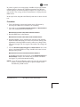
Log-in and Configuration Procedure
The following is an overview of the local log-in and configuration pro-
cedure using the
COM1
serial port. For detailed instructions on this,
and other methods of control, refer to the
Mercury Reference Manual
.
a. Connect a computer’s serial port to the
COM1
Port of the radio.
b. Launch a terminal communication program, such as Hyper-
Terminal, on the computer. (Configure terminal to: 115,200
bps/8N1/no handshaking/VT100.)
c. Press the
ENTER
key. A login prompt will be displayed that
requires a username and password.
d. Enter the username and password (default entries are
admin
).
e. Change the radio’s network name from the default entry of
MDS-Mercury
. This can be changed under the
Radio Configura-
tion Menu
for both AP and Remote.
f. Review other settings and make changes as necessary, such as
the unit password, IP address, and security.
g. Under the Radio Configuration Menu at the Access Point,
set/verify the following:
Transmit Power
—Settable from: -30 dBm to +30 dBm (AP);
0 dBm to +30 dBm (Remote); +20 dBm for 3650 models.
Receive Power
—Target receive signal of the AP which
Remotes will have to adjust based on distance.
h. Under the
Frequency Control
Menu of the
Radio Configuration
Menu set/verify the following:
Frequency Mode
—Single Channel
Single Frequency
—Channel (0 to 13)
Frame Duration
—for a 1.75 Mhz channel, use either 10 or 20
milliseconds.
i. Ensure that the Remote's radio parameters are consistent with
the AP's network name and the Frequency Control Parameters.
Repeat above steps for each unit in the network.

05-4558A01, Rev. C MDS Mercury Series Startup Guide
7
NOTE:
Using
Configuration Scripts
under the
Maintenance/Tools
menu will aid in uniformly configuring multiple units. See the
Mercury Reference Manual
for details.
Step 5—Connect the Data Equipment
Connect Ethernet-compatible data equipment to the unit’s
LAN
port
(10/100 BaseT), or one of the serial ports, depending on the capability
of your transceiver.
Use a straight-through Ethernet cable to connect the
LAN
port
to a hub
or switch, and a crossover cable to connect it directly to an Ethernet
station (PC, PLC, RTU).
Step 6—Check for Normal Operation
This step verifies the proper operation of wireless communications
between an Access Point and its associated Remotes.
At All Units...
Observe the transceiver’s LED panel (See
Installation Setup Chart
)
for the proper indications. In a normally operating system, the radio
will typically become associated in about two minutes from start-up.
At the Access Point...
a. If the Access Point unit is the first unit you are installing, send
a
PING
command to it through the
LAN
port. This verifies basic
LAN
connectivity.
b. If you have already installed a Remote unit, try sending a
PING
to that unit through the Menu System
PING
utility or a device
connected to the unit on the same subnet.
At Remotes...
a. Look for the
LINK
LED to turn on and stay on. This indicates
the unit has successfully associated with the network’s Access
Point. (The association process may take up to 30 seconds.)
b. Check the
Starting Information
screen for the
Device Status
(also known as Connection Status). It will show one of the fol-
lowing:
Initializing
—This is the first phase after boot-up.

8 MDS Mercury Series Startup Guide 05-4558A01, Rev. C
Scanning
—The unit is looking for an Access Point beacon signal.
Ranging
—Unit is adjusting power, timing, and frequency with an AP.
Connecting
—Unit has an RF connection with the AP.
Authenticating
—(When Device Authentication is in use) The Remote
is authenticating itself to the network to obtain security clearance.
Associated
—The unit has successfully synchronized and associated
with an Access Point. This is the normal status.
Alarmed—The unit is has detected one or more alarms that have not
been cleared.
c. When the network is operating properly based on observation
of the unit’s LEDs, connect a computer to the transceiver’s
data port that will be used by the local terminal equipment.
Send the
PING command to verify communications link integ-
rity with the Access Point.
d. After the
PING is successful, connect the terminal equipment
to the radio’s data port and verify normal operation.
If all checks are OK, you are finished with the installation at this site.
Resetting to Factory Defaults (Use with Caution)
Selecting Maintenance/Tools>Reset to Factory Defaults sets all trans-
ceiver parameters back to their factory defaults. This may be useful
when several parameters have been modified and there is no track of
changes. It causes the transceiver to return to a known factory state.
Use this function with care, as all user-customized settings will be
cleared.
AIMING DIRECTIONAL ANTENNAS
Directional antennas usually require some fine-tuning of their bearing
to optimize the received signal strength. The unit has a built-in
received signal strength indicator (RSSI) that can be used to optimize
the received signal level. It is available under the
Performance Informa-
tion
menu.

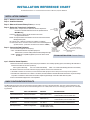
MENU SYSTEM
Flowchart
CONNECTORS AND INDICATORS
LED FUNCTIONS & INDICATIONS
LAN ......ON ............LAN detected
Flashing....Data TX/RX
OFF ..........LAN not detected
COM1 ...Flashing ....Data TX/RX Activity
OFF ..........No data activity
GPS ...ON ............Has satellite fix
Flashing....Synchronizing
OFF ..........No satellite fix
Standard Unit
Option Set 1
Remote
Insert to P/N 05-4458A01
GE MDS
175 Science Parkway
Rochester, NY 14620 USA
www.GEmds.com
Ntwk. Intfc. Config
Ethernet Port Config
Bridge Configuration
SNMP Agent Config. (AP)
AP Location Info (RM)
SNTP Server Config.
Network
Configuration
Radio
Configuration
Device
Information
Maintenance/Tools
Security
Configuration
Reprogramming
Config. Scripts
Ping Utility
Auth. Codes
Reset to Defaults
Radio Test
F/W Versions
F/W Upgrade
MAIN MENU
Network Name
Transmit Power
Receive Pwr. (AP)
Freq. Control
Adv. Config.
Performance
Information
NOTES
• Chart shows top-level view only. See Reference Manual for details.
• Not all menu items are-user configurable
Serial Number
Uptime
Date
Date Format
Time
Model
Device Names
Console Bd. Rt.
UTC Time Offset
Device Security
Wireless Security
Event Log
Packet Statistics
GPS Status
Wireless Ntwk Stat.
Intl. Radio Stat. (RM)
Performance Trend
Manage Certif.
RADIUS
Configuration
Starting Information Screen
(Read-Only Status)
Redundancy
Configuration (AP)
Redundancy Config.
Ntwk Event Triggers
Radio Event Triggers
Hdwr Event Triggers
Red. Config. Options
Force Switchover
GPS
Configuration (RM)
Stream GPS to Console
Send GPS via UDP
GPS UDP Server IP Address
GPS UDP Server UDP Port
PWR .....ON ............Primary power (DC) present
Flashing....Alarm present
OFF ..........Primary power (DC) absent
Access Point
Remote Gateway
LINK .....ON ............Default state
Flashing....Data Tx/Rx
LINK .....ON ............Associated to AP
Flashing....Data Tx/Rx
OFF ..........Not Associated with AP
COM1
SERIAL PORT
LAN PORTS
GPS ANTENNA
CONNECTION
RX2 ANTENNA
PORT
TX/RX1
ANTENNA PORT
DC POWER INPUT
(10—30 VDC, 2.5A)
LED INDICATOR
PANEL
WiFi ANTENNA
PORT
USB PORTS
(Mini-A, Type-A)
• Spacebar is used to make some menu selections
• AP = Access Point Only
• RM = Remote Only
COM1
SERIAL PORT
LAN PORT
GPS ANTENNA
CONNECTION
RX2 ANTENNA
PORT
TX/RX1
ANTENNA PORT
DC POWER INPUT
(10—30 VDC, 2.5A)
LED INDICATOR
PANEL

TO DC POWER SUPPLY
(10–30 Vdc)
RTU/PLC
(Crossover Cable
to Radio)
LOW-LOSS FEEDLINE
(To 900 MHz Antenna)
INST
INST
ALLA
ALLA
TION REFERENCE CHART
TION REFERENCE CHART
ANTENNA
SYSTEM
PC RUNNING
TERMINAL
PROGRAM
(Straight-Through
Cable to Radio)
TO GPS ANTENNA
(Provides 3.3 Vdc output)
Step 1 – Mount the Transceiver
Step 2 – Install the Antennas
Step 3 – Measure & Connect Primary Power
(10–30 Vdc)
Step 4 – Review the Transceiver’s Configuration
Network Name—Unique name for each radio network. Required for
Remotes to associate with the Access Point. (Default name is
MDS-Mercury.)
IP Address—Must be a unique number to allow for IP access
through the Ethernet Port.
NOTE: A unique IP address is essential to access the web browser-based
Management System.
RF Output Power—Adjust as necessary for regulatory compliance.
Username/Password—Used for remote access and some Management
System features. (Username and Password default = admin)
Step 5 – Connect the Data Equipment
Connect the data equipment to data port(s):
• LAN—10/100BaseT Ethernet-compatible equipment:
Ethernet PLC (Crossover cable); Ethernet switch (Straight-Through)
• COM1—RS/EIA-232 compatible equipment (Crossover cable to serial
PLC/RTU)
tep 6 – Check for Normal Operation
Observe the transceiver LED status panel for the proper indications. In a normally operating system, the following LED indications s
hould be seen within 30 seconds of power-up:
WR—Lights continuouslyL AN—On or blinks intermittently LINK— On or blinks intermittently (Remotes: if associated)
U se PING command to test basic data link integrity between Access Point and Remotes.
I f the PING command is successful, connect the RTU/data equipment to the data port and verify normal operation.
I f the LINK LED on Remotes is not on after 2 or 3 minutes, the unit has failed to associate with the Access Point. It may be necessary t
o reposition or redirect the radio’s antenna for better reception/signal strength. Check also GPS antenna system.
C heck connected data equipment for normal operation.
Detailed instructions are contained in the Reference Manual, P/N 05-4446A01
INSTALLATION SUMMARY
BASIC CONFIGURATION DEFAULTS
TYPICAL INSTALLATION—Remote Shown
The Management System can be accessed through the COM1 Port using a terminal emulator. The basic items listed below, and
many other parameters and tools can be accessed through this tool. HTTP, Telnet access, and changing parameters are controlled
by password.
VALUES/RANGE
•1–8 alphanumeric characters
•Case-sensitive; can be mixed case
• 1–16 alphanumeric characters
• Case-sensitive; can be mixed case
Contact your Network Administrator
AP: -30 to +30 dBm RM: 0 to +30 dBm
DEFAULT
admin (lower case)
ITEM MGT SYSTEM MENU
Username/Password Device Information
Network Name Network Configuration
IP Address Network Configuration
RF Output Power Radio Configuration
MDS-Mercury
192.168.1.1
+30 dBm (900 model)
+20 dBm (3650 model)

05-4558A01, Rev. C MDS Mercury Series Startup Guide 9
In general, signal levels stronger than –80 dBm will provide reliable
communication in the network. RSSI measurements and Wireless
Packet Statistics are based on multiple samples over a period of sev-
eral seconds. The average of these measurements is displayed by the
RSSI screen.
In the steps below, the path to the Menu System item is shown in bold
text.
Procedure
1. Verify the Remote is associated with an Access Point unit by
observing the LINK LED. It should be on or blinking.
2. View and record the
Wireless Packets Dropped and Received Error
rates. This information will be used later.
Main Menu>Performance Information>Packet Statistics
3. Read the RSSI level at the Remote.
Main Menu>Performance Information>Internal Radio Status
4. Optimize RSSI by slowly adjusting the direction of the antenna.
Watch the RSSI indication for several seconds after making each
adjustment so that the RSSI accurately reflects any change in the
link signal strength. The less negative the number, the stronger the
signal.
5. View the
Wireless Packets Dropped and Received Error rates at the
point of maximum RSSI level. They should be the same or lower
than previously noted.
Main Menu>Performance Information>Packet Statistics
If the RSSI peak results in an increase in the Packets Dropped and
Received Error numbers, the antenna may be aimed at an undes-
ired signal. Try a different antenna heading.
NOTE: Access Points and Remote stations must use the same antenna
polarity (vertical or horizontal) or signal strengths will be
attenuated by 20 dB or more.

10 MDS Mercury Series Startup Guide 05-4558A01, Rev. C
TRANSMITTER POWER & ANTENNA TEST
The following procedure may be used to measure the transmitter’s RF
power output and SWR “match” of the antenna system. A directional
wattmeter is required for the test, such as a Bird Model 43, with an
appropriate element installed.
Before you start, keep in mind that using the Test Mode will disrupt
network operation.
Procedure
1. Connect a directional wattmeter between the ANTENNA port and
the antenna system.
2. Place the transceiver into the Radio Test Mode.
Main Menu>Maintenance/Tools Menu>Radio Test>Radio Mode>Test
NOTE: The Test Mode has a 10-minute timer, after which it will
return the transceiver to normal operation. The Test Mode can
also be terminated manually, via the menu.
3. Set the transmitter RF output power to +28 dBm.
Main Menu>Radio Configuration>Transmit Power
NOTE: The Test Mode RF power setting does not affect the output
level during normal operation
4. Activate (key) the transmitter.
Main Menu>Maintenance/Tools>Radio Test>Test Mode>
TxKey> Enable
Use the spacebar to key and unkey the transmitter ON and OFF
(Enable/Disable).
5. Using the wattmeter, measure the forward and reflected power
into the antenna system and calculate the SWR. The ratio should
be less than 2:1. Higher levels may indicate a problem with the
antenna or feedline.
6. Turn off Test Mode at the Access Point and Remote radio.
Main Menu>Maintenance/Tools>Radio Test>Radio Mode>Normal

05-4558A01, Rev. C MDS Mercury Series Startup Guide 11
TROUBLESHOOTING
It is best to begin troubleshooting at the Access Point, as the rest of the
system depends on it for network synchronization and configuration.
If the Access Point has problems, the operation of the entire network
will be affected.
All radios in the network must meet these basic requirements:
• Adequate and stable primary power
• An efficient and properly aligned antenna system
• Secure connections (RF, data & power)
• Proper programming of the unit’s operating parameters, espe-
cially Frequency Mode Selection, Network Name, and IP
Address
• The correct interface between the radio and the connected data
equipment (proper cable wiring, data format and timing)
Table 1 provides suggestions for resolving common system difficul-
ties using the radio’s LEDs as a guide. Table 2 on Page 13 provides
guidance for using the Menu System as a tool.
If problems cannot be resolved using the guidance provided here,
review the GE MDS web site’s technical support area for recent soft-
ware/firmware updates, general troubleshooting help, and service
information. Additional help is available through our Technical Sup-
port Department.
Table 1. Troubleshooting Using LEDs
Symptom Problem/Recommended Checks
PWR LED
not lit.
a. Voltage too low—Check for proper supply voltage at
the power connector (10–30 Vdc).
b. Indefinite Problem—Cycle the power and wait
(≈ 30 seconds) for the unit to reboot. Then, recheck for
normal operation.
PWR LED is
blinking.
a. Blinking indicates the presence of an alarm condition.
b. View Current Alarm List and Error Log and correct the
problem if possible.
c. Blinking continues until the fault is corrected, for
example, a valid IP address is entered, etc.

12 MDS Mercury Series Startup Guide 05-4558A01, Rev. C
LINK LED
not lit.
a. Network Names of APs and Remotes do not match.
They must be identical for association to occur—Also,
verify that the system has a unique Network Name.
b. Remote not yet associated with an Access Point with
the same Network Name.
Check the “Status” of the unit’s process of associating
with the Access Point. Use the Menu System.
c. Poor Antenna System—Check the antenna, feedline
and connectors. Reflected power should be less than
10% of the forward power reading (SWR 2:1 or lower).
d. Wrong Frequency Mode parameters where units need
to be time synchronized. Frequency Mode parameters
are channel, bandwidth and pattern offset.
e. Wrong encryption settings—The Encryption Enable
and Encryption Phrase must match on the AP and
Remote.
f. Wrong device authentication settings—Verify settings
match on AP and Remote.
LAN LED not
lit.
a. Verify the Ethernet cable is connected at both ends.
b. Verify that the appropriate type of Ethernet cable is
used: straight-through, or crossover as required.
c. Verify setting of parameter Eth Port Follows
Association if selected or enabled. If enabled, LED
does not light when Remote is not associated.
GPS LED
not lit
Indicates no GPS fix has been obtained. This only applies
when GPS operation is desired.
a. Check connection of GPS antenna cable and the
antenna itself. Is there a clear “view” to satellites?
Note: Blinking LED indicates establishing TDD Sync.
Table 1. Troubleshooting Using LEDs (Continued)
Symptom Problem/Recommended Checks

05-4558A01, Rev. C MDS Mercury Series Startup Guide 13
Table 2. Troubleshooting with the Menu System
Symptom Problem/Recommended System Checks
Cannot Access the
Remote or AP
through COM1
Only occurs in three possible scenarios:
—COM1 is damaged or the Unit is faulty.
—COM1 is being used for Streaming GPS
information to Console terminal.
—COM1 is being used for serial data.
a. Connect to unit via Telnet or Web browser
b. Disable the serial mode for COM1
(Serial Gateway Configuration>Com1 Serial
Data Port>Status>Disabled)
or, if you know the unit’s data configuration...
c. Connect to COM 1 via a terminal set to VT100
and the port's data baud rate to xxxx bps (4800
for GPS) 8N1.
d. Port in Data mode. Enter escape sequence “+++”.
Cannot pass IP
data to WAN.
a. Verify your IP settings.
b. Use the PING command to test communication
with units in the local radio system.
c. If successful with local PING, attempt to PING an
IP unit attached to another radio.
d. If successful with the LAN PINGs, try connecting
to a known unit in the WAN.
Excessive Wireless
Retries.
Possible Radio Frequency Interference (RFI)—
a. If omnidirectional antennas are used, consider
changing to directional antennas. This will often
limit interference to and from other stations.
b. Try skipping channels where persistent
interference is known or suspected.
c. The installation of a filter in the antenna feedline
may be necessary. Consult the factory for further
assistance.
Password
forgotten.
a. Connect to the unit using a terminal through the
COM1 Port.
b. Consult the factory. Get a password-resetting
Authorization Key.
c. Enter the Authorization Key at the login prompt
as a password. Use login name authcode.

14 MDS Mercury Series Startup Guide 05-4558A01, Rev. C
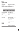
SPECIFICATIONS
GENERAL
Temperature Range: –40° C to +70° C (–40° F to 158° F)
Humidity: 95% at +40° C (104° F); non-condensing
Primary Power: 10–30 Vdc
External Power Supply Options: 48 Vdc; 110–120/210–220 Vac
Typical Current Consumption (assumes 1 Watt RF Output):
Size (without mtg. hardware): 5.72 H x 20 W x 12.38 D cm
(2.25 H x 7.88 W x 4.88 D in.)
Mounting Options: Flat surface brackets, DIN rail, 19” rack
Weight: 1kg / 2.2 lb.
Case: Die Cast Aluminum
RADIO CHARACTERISTICS
GENERAL:
Frequency Band: Mercury 900: 902–928 MHz
Industrial, Scientific & Medical (ISM) Band
Mercury 3650: 3650–3700 MHz
FCC Registered Band
TRANSMITTER:
RF Output @ connector: Mercury 900: –30 to +30 dBm
Mercury 3650: 0 to 20 dBm
Increments of 1.0 dB, set by user
Duty Cycle: Continuous
Output Impedance: 50 Ohms
RECEIVER:
Type: Double conversion superheterodyne
Sensitivity and Data Rate: Dependent on modulation and bandwidth.
See Reference Manual Specifications.
Mode DC Power 13.8 Vdc 24 Vdc
AP Transmit 25 W 1.8 A 1.0 A
AP Receive 8 W 579 mA 333 mA
RM Transmit 25W 1.8 A 1.0 A
RM Receive 6.5W 471 mA 270 mA

05-4558A01, Rev. C MDS Mercury Series Startup Guide 15
PHYSICAL INTERFACE: Ethernet: 10/100BaseT, RJ-45
Serial: (COM1) RS-232, DB-9F
APPROVALS: FCC Part 15.247 (DTS)
CSA
/US Class 1, Div. 2
Industry Canada RS-210
PROTOCOLS: Ethernet: IEEE 802.3, Spanning Tree
(Bridging), VLAN, IGMP
TCP/IP: DHCP, ICMP, UDP, TCP. ARP,
Multicast, SNTP, TFTP
Serial: Encapsulation over IP (tunneling)
for serial async multidrop protocols includ-
ing Modbus, DNP.3, DF1, BSAP
MANAGEMENT: HTTP, HTTPS, TELNET, SSH, local
console
SNMPv1/v2/v3, MIB-II, Enterprise MIB,
SYSLOG, MDS NETview MS
TM
compati-
ble

16 MDS Mercury Series Startup Guide 05-4558A01, Rev. C
TECHNICAL ASSISTANCE
Technical assistance is available from our Technical Support Depart-
ment during business hours (8:30 A.M.–7:00 P.M. Eastern Time).
When calling, please give the complete model number of the radio,
along with a description of the trouble symptom(s) that you are expe-
riencing. In many cases, problems can be resolved over the telephone,
without the need for returning the unit to the factory.
Phone: 585 241-5510 E-Mail: [email protected]
FAX: 585 242-8369 Web: www.GEmds.com
FACTORY SERVICE
If return of the equipment is necessary, please contact our Technical
Support Team. You will be issued a Service Request Order (SRO)
number. The SRO number will help expedite the repair so that the
equipment can be repaired and returned to you as quickly as possible.
Please be sure to include the SRO number on the outside of the ship-
ping box, and on any correspondence relating to the repair. No equip-
ment will be accepted for repair without an SRO number.
A statement should accompany the radio describing, in detail, the
trouble symptom(s), and a description of any associated equipment
normally connected to the radio. It is also important to include the
name and telephone number of a person in your organization who can
be contacted if additional information is required.
The radio must be properly packed for return to the factory. The orig-
inal shipping container and packaging materials should be used when-
ever possible. All factory returns should be addressed to:
When repairs are complete, the equipment will be returned by the
same shipping method used to send it to the factory. Please specify if
you wish to make different shipping arrangements. To inquire about
an in-process repair, contact our Product Services Group using the
telephone, Fax, or E-mail information given above
.
GE MDS
Customer Service Department
(SRO No. XXXX)
175 Science Parkway
Rochester, NY 14620 USA

GE MDS, LLC
Rochester, NY 14620
General Business: +1 585 242-9600
FAX: +1 585 242-9620
Web: www.GEmds.com
175 Science Parkway
-
 1
1
-
 2
2
-
 3
3
-
 4
4
-
 5
5
-
 6
6
-
 7
7
-
 8
8
-
 9
9
-
 10
10
-
 11
11
-
 12
12
-
 13
13
-
 14
14
-
 15
15
-
 16
16
-
 17
17
-
 18
18
-
 19
19
-
 20
20


GE MDS 05-4558A01 User manual
- Category
- Television antennas
- Type
- User manual
- This manual is also suitable for
Ask a question and I''ll find the answer in the document
Finding information in a document is now easier with AI
Related papers
Other documents
-
MDS E5MDS-INETII User manual
-
GE MDS MDS iNET-II 900 User manual
-
 CalAmp Phantom II User manual
-
 CalAmp Viper SC+ User manual
-
-
 CalAmp GEMINI G3 User manual
-
 CalAmp ITC 220 Wayside User manual
-
 AirLink Communications X EV-DO User manual
-
Cisco Systems 9216 User manual
-
 CalAmp ITC 220 Field User manual


