
®
P4T-EM
Intel
®
850 ATX Motherboard
USER’S MANUAL

2 ASUS P4T-EM User’s Manual
USER'S NOTICE
Product Name: ASUS P4T-EM
Manual Revision: 1.00 E903
Release Date: November 2001
No part of this manual, including the products and software described in it, may be repro-
duced, transmitted, transcribed, stored in a retrieval system, or translated into any language in
any form or by any means, except documentation kept by the purchaser for backup purposes,
without the express written permission of ASUSTeK COMPUTER INC. (“ASUS”).
ASUS PROVIDES THIS MANUAL “AS IS” WITHOUT WARRANTY OF ANY KIND,
EITHER EXPRESS OR IMPLIED, INCLUDING BUT NOT LIMITED TO THE IMPLIED
WARRANTIES OR CONDITIONS OF MERCHANTABILITY OR FITNESS FOR A PAR-
TICULAR PURPOSE. IN NO EVENT SHALL ASUS, ITS DIRECTORS, OFFICERS,
EMPLOYEES OR AGENTS BE LIABLE FOR ANY INDIRECT, SPECIAL, INCIDEN-
TAL, OR CONSEQUENTIAL DAMAGES (INCLUDING DAMAGES FOR LOSS OF
PROFITS, LOSS OF BUSINESS, LOSS OF USE OR DATA, INTERRUPTION OF BUSI-
NESS AND THE LIKE), EVEN IF ASUS HAS BEEN ADVISED OF THE POSSIBILITY
OF SUCH DAMAGES ARISING FROM ANY DEFECT OR ERROR IN THIS MANUAL
OR PRODUCT.
Product warranty or service will not be extended if: (1) the product is repaired, modified or
altered, unless such repair, modification of alteration is authorized in writing by ASUS; or (2)
the serial number of the product is defaced or missing.
Products and corporate names appearing in this manual may or may not be registered trade-
marks or copyrights of their respective companies, and are used only for identification or
explanation and to the owners’ benefit, without intent to infringe.
• Adobe and Acrobat are registered trademarks of Adobe Systems Incorporated.
• Intel, LANDesk, and Pentium are registered trademarks of Intel Corporation.
• Trend and ChipAwayVirus are trademarks of Trend Micro, Inc.
• Windows and MS-DOS are registered trademarks of Microsoft Corporation.
The product name and revision number are both printed on the product itself. Manual revi-
sions are released for each product design represented by the digit before and after the period
of the manual revision number. Manual updates are represented by the third digit in the manual
revision number.
For previous or updated manuals, BIOS, drivers, or product release information, contact ASUS
at http://www.asus.com.tw or through any of the means indicated on the following page.
SPECIFICATIONS AND INFORMATION CONTAINED IN THIS MANUAL ARE FUR-
NISHED FOR INFORMATIONAL USE ONLY, AND ARE SUBJECT TO CHANGE AT
ANY TIME WITHOUT NOTICE, AND SHOULD NOT BE CONSTRUED AS A COM-
MITMENT BY ASUS. ASUS ASSUMES NO RESPONSIBILITY OR LIABILITY FOR
ANY ERRORS OR INACCURACIES THAT MAY APPEAR IN THIS MANUAL, INCLUD-
ING THE PRODUCTS AND SOFTWARE DESCRIBED IN IT.
Copyright © 2001 ASUSTeK COMPUTER INC. All Rights Reserved.

ASUS P4T-EM User’s Manual 3
ASUS CONTACT INFORMATION
ASUSTeK COMPUTER INC. (Asia-Pacific)
Marketing
Address: 150 Li-Te Road, Peitou, Taipei, Taiwan 112
Telephone: +886-2-2894-3447
Fax: +886-2-2894-3449
Email: [email protected]
Technical Support
MB/Others (Tel): +886-2-2890-7121 (English)
Notebook (Tel): +886-2-2890-7122 (English)
Desktop/Server (Tel):+886-2-2890-7123 (English)
Fax: +886-2-2980-7698
Email: [email protected]
WWW: www.asus.com.tw
FTP: ftp.asus.com.tw/pub/ASUS
Newsgroup: csnews.asus.com.tw
ASUS COMPUTER INTERNATIONAL (America)
Marketing
Address: 6737 Mowry Avenue, Mowry Business Center, Building 2
Newark, CA 94560, USA
Fax: +1-510-608-4555
Email: [email protected]
Technical Support
Fax: +1-510-608-4555
Email: [email protected]
WWW: www.asus.com
FTP: ftp.asus.com/Pub/ASUS
ASUS COMPUTER GmbH (Europe)
Marketing
Address: Harkortstr. 25, 40880 Ratingen, BRD, Germany
Fax: +49-2102-442066
Email: [email protected] (for marketing requests only)
Technical Support
Hotline: MB/Others: +49-2102-9599-0 Notebook: +49-2102-9599-10
Fax: +49-2102-9599-11
Support (Email): www.asuscom.de/de/support (for online support)
WWW: www.asuscom.de
FTP: ftp.asuscom.de/pub/ASUSCOM

4 ASUS P4T-EM User’s Manual
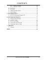
CONTENTS
1. INTRODUCTION ............................................................................. 7
1.1 How This Manual Is Organized .................................................. 7
1.2 Item Checklist ............................................................................. 7
2. FEATURES ........................................................................................ 8
2.1 The ASUS P4T-EM..................................................................... 8
2.1.1 Core Specifications.......................................................... 8
2.1.2 Connections ..................................................................... 9
2.1.3 Optional Components .................................................... 10
2.1.4 Performance and Intelligence ........................................ 10
2.2 P4T-EM Motherboard Components.......................................... 12
3. HARDWARE SETUP ...................................................................... 14
3.1 P4T-EM Motherboard Layout................................................... 14
3.2 Layout Contents ........................................................................ 15
3.3 Hardware Setup Procedure ....................................................... 16
3.4 Motherboard Settings................................................................ 16
3.5 System Memory ........................................................................ 21
3.6 Central Processing Unit (CPU) ................................................. 23
3.7 Expansion Cards ....................................................................... 27
3.8 External Connectors.................................................................. 30
3.9 Starting Up the First Time ........................................................ 41
4. BIOS SETUP..................................................................................... 43
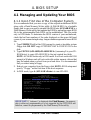
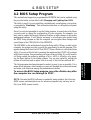
4.1 Managing and Updating Your BIOS ......................................... 43
4.1.1 Upon First Use of the Computer System....................... 43
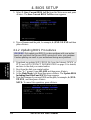
4.1.2 Updating BIOS Procedures ........................................... 44
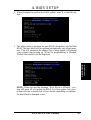
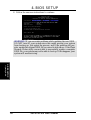
4.2 BIOS Setup Program ................................................................ 47
4.2.1 BIOS Menu Bar ............................................................. 48
4.2.2 Legend Bar .................................................................... 48
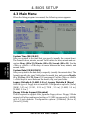
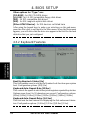
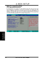
4.3 Main Menu................................................................................ 50
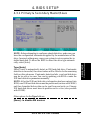
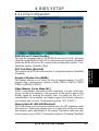
4.3.1 Primary & Secondary Master/Slave .............................. 51
4.3.2 Keyboard Features ......................................................... 54
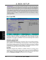
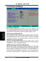
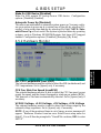
4.4 Advanced Menu ........................................................................ 56
4.4.1 Chip Configuration ........................................................ 59
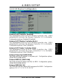
4.4.2 I/O Device Configuration .............................................. 61
4.4.3 PCI Configuration ......................................................... 63
4.4.4 Shadow Configuration................................................... 65
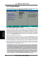
4.5 Power Menu .............................................................................. 66

ASUS P4T-EM User’s Manual 5
CONTENTS
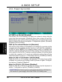
4.5.1 Power Up Control .......................................................... 68
4.5.2 Hardware Monitor ......................................................... 69
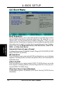
4.6 Boot Menu ................................................................................ 70
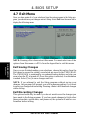
4.7 Exit Menu ................................................................................. 72
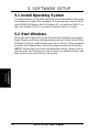
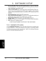
5.1 Install Operating System........................................................... 74
5.2 Start Windows........................................................................... 74
5. SOFTWARE SETUP....................................................................... 75
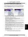
5.3 P4T-EM Motherboard Support CD........................................... 75
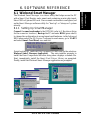
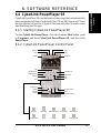
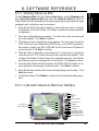
6. SOFTWARE REFERENCE ........................................................... 77
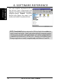
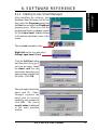
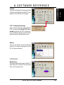
6.1 Winbond Smart Manager .......................................................... 77
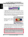
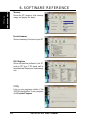
6.2 ASUS PC Probe ........................................................................ 81
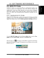
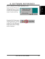
6.3 ASUS Live Update ................................................................... 86
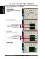
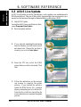
6.4 CyberLink PowerPlayer SE ...................................................... 87
6.5 CyberLink VideoLive Mail ....................................................... 88
7. APPENDIX....................................................................................... 91
7.1 Glossary .................................................................................... 91
INDEX ................................................................................................... 95

6 ASUS P4T-EM User’s Manual
FCC & DOC COMPLIANCE
This device complies with FCC Rules Part 15. Operation is subject to the following
two conditions:
• This device may not cause harmful interference, and
• This device must accept any interference received, including interference that
may cause undesired operation.
This equipment has been tested and found to comply with the limits for a Class B
digital device, pursuant to Part 15 of the FCC Rules. These limits are designed to
provide reasonable protection against harmful interference in a residential installa-
tion. This equipment generates, uses and can radiate radio frequency energy and, if
not installed and used in accordance with manufacturer's instructions, may cause
harmful interference to radio communications. However, there is no guarantee that
interference will not occur in a particular installation. If this equipment does cause
harmful interference to radio or television reception, which can be determined by
turning the equipment off and on, the user is encouraged to try to correct the interfer-
ence by one or more of the following measures:
• Re-orient or relocate the receiving antenna.
• Increase the separation between the equipment and receiver.
• Connect the equipment to an outlet on a circuit different from that to which the
receiver is connected.
• Consult the dealer or an experienced radio/TV technician for help.
WARNING! Any changes or modifications to this product not expressly ap-
proved by the manufacturer could void any assurances of safety or performance
and could result in violation of Part 15 of the FCC Rules.
Reprinted from the Code of Federal Regulations #47, part 15.193, 1993. Washington DC: Office of the
Federal Register, National Archives and Records Administration, U.S. Government Printing Office.
Canadian Department of Communications Statement
This digital apparatus does not exceed the Class B limits for radio noise emissions
from digital apparatus set out in the Radio Interference Regulations of the Canadian
Department of Communications.
This Class B digital apparatus complies with Canadian ICES-003.
Cet appareil numérique de la classe B est conforme à la norme NMB-003 du Canada.

ASUS P4T-EM User’s Manual 7
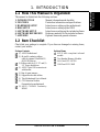
1.1 How This Manual Is Organized
This manual is divided into the following sections:
1. INTRODUCTION Manual information and checklist
2. FEATURES Production information and specifications
3. HARDWARE SETUP Intructions on setting up the motherboard.
4. BIOS SETUP Intructions on setting up the BIOS
5. SOFTWARE SETUP Intructions on setting up the included software
6. SOFTWARE REFERENCE Reference material for the included software
7. APPENDIX Optional items and general reference
1.2 Item Checklist
Check that your package is complete. If you discover damaged or missing items,
contact your retailer.
1. INTRODUCTION
1. INTRODUCTION
Manual / Checklist
Package Contents
(1) ASUS Motherboard
(1) 40-pin 80-conductor ribbon
cable for internal UltraDMA33/
66/100 IDE drives
(1) Ribbon cable for (1) 5.25” and (2)
3.5” floppy disk drives
(1) ASUS 2-port USB connector set
with bracket
(1) Bag of spare jumpers
(1) Support drivers and utilities
(1) This Motherboard User’s Manual
(1) CPU Retention Module
(Preinstalled on motherboard)
(2) ASUS C-RIMM Continuity
RIMM
Optional Items
ASUS IrDA-compliant infrared
module
Two Rambus Memory Modules
LAN Card: PCI-L3C920
1394 Card: PCI-1394E

8
ASUS P4T-EM User’s Manual
Core Specifications
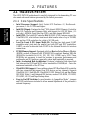
2. FEATURES
2.1 The ASUS P4T-EM
The ASUS P4T-EM motherboard is carefully designed for the demanding PC user
who wants advanced features processed by the fastest processors.
2.1.1 Core Specifications
2. FEATURES
• Intel Processor Support: Intel Socket 478 Pentium
®
4 / Northwood
™
processors, 1.4 to 2.0 GHz and higher.
• Intel 850 Chipset: Features the Intel
®
850 chipset (82850 Memory Controller
Hub, I/O Controller and Firmware Hub) with support for AGP 4X Mode, (1.5
volt only); 400MHz Front Side Bus (FSB); and dual channel RDRAM.
• Intel ICH2: The Intel I/O Controller Hub 2 (82801 ICH2) features support for
UltraDMA/100, which allows burst mode data transfer rates of up to 100MB/
sec; and two USB controllers for a total of 4 USB ports.
• Low Pin Count (LPC) Super Multi-I/O: Provides two high-speed UART
ompatible serial ports and one parallel port with EPP and ECP capabilities.
UART2 can also be directed from COM2 to the Infrared Module for wireless
connections.
• PC800 Memory Support: Equipped with four Rambus Inline Memory Module
(RIMM) sockets to support Intel PC800/PC600-compliant Rambus DRAMs
(RDRAMs) (available in 64, 96, 128, 192, 256, 512MB) up to 2GB. These
RDRAMs are necessary to meet the increase in processor performance and
multimedia and 3D functions, especially where high bandwidth is required.
• Intel
®
Accelerated Hub Architecture: Features a dedicated high speed hub
link between the ICH2 and MCH with a bandwidth of 266MB/sec – twice the
maximum bandwidth of the PCI bus.
• UltraDMA/100 Support: Comes with an onboard PCI Bus Master IDE controller
with two connectors that support four IDE devices on two channels. Supports
UltraDMA/100, UltraDMA/66, UltraDMA/33, PIO Modes 3 & 4 and Bus Master
IDE DMA Mode 2, and Enhanced IDE devices, such as DVD-ROM, CD-ROM,
CD-R/RW, LS-120, and Tape Backup drives.
• Easy-to-Use DIP Switches: As an alternative to JumperFree Mode
™
, jumpers
and DSW switches are included to allow manual adjustment of the processor’s
external frequency.

ASUS P4T-EM User’s Manual 9
2. FEATURES
2. FEATURES
Connections
2.1.2 Connections
• CPU socket: 478-pin surface mount, ZIF socket mPGA478 B.
• PCI Expansion Slots: Provides two 32-bit PCI slots, (PCI 2.2 compliant) with
no ISA, eliminating bottlenecks and system memory management issues. All
PCI slots can support Bus Master PCI cards, such as SCSI or LAN cards. (PCI
supports up to 133MB/s maximum throughput.) The MB supports Concurrent
PCI, which allows multiple PCI transfers from PCI master bus to the memory
and processor.
• AGP Slot: Comes with an Accelerated Graphics Port slot that supports AGP
cards for high performance, component level interconnect targeted at 3D graphical
applications using a 4X mode bus. The slot is keyed to support only the latest
1.5 volt AGP cards: ASUS V3800 and newer versions.
• CNR Support: A Communication and Networking Riser (CNR) slot provides
an interface to support very affordable multichannel audio, V.90 analog modem,
Home PNA, 10/100 Ethernet networking, and a USB hub.
• IDE connectors: Dual-channel bus master IDE connectors support up to four
Ultra DMA/100/66, PIO Modes 3 & 4 IDE devices. Both the primary (blue) and
secondary (black) connectors are slotted to prevent incorrect insertion of the
IDE ribbon cable.
• Floppy disk connector: Supports the floppy disk drive ribbon cable. One side
of the connector is slotted to prevent incorrect insertion of the floppy disk cable.
• Smartcard Reader Connector: PS/SC compatible.
• Intel Front Panel Connector: Supports easy USB connectivity, control and
monitoring of major PC functions.
• USB ports: Four Universal Serial Bus (USB) ports are available for connecting
USB devices such as a mouse and PDA.
• IrDA: Supports an optional infrared port module for a wireless interface.
• Serial ports: Two 9-pin COM1/COM2 ports are for pointing devices or other
serial devices.
• Parallel port: 25-pin port connects a parallel printer or other devices.
• PS/2 mouse port: Green 6-pin connector is for a PS/2 mouse.
• PS/2 keyboard port: Purple 6-pin connector is for a PS/2 keyboard.
• Onboard LED: Signals AC power is okay.
• ATX power connector. Supplies the MB with ATX power.
• Microphone jack (optional): Pink jack connects a microphone.
• Line In jack (optional): Light blue jack connects a tape player or other audio
sources.
• Line Out jack (optional): Lime jack connects a headphone or a speaker.
• Game/MIDI connector (optional): This connector supports a joystick or a game
pad for playing games, and MIDI devices.

10
ASUS P4T-EM User’s Manual
2.1.3 Optional Components
• AC’97 Codec: The latest high-performance mini-chipset supports hi-fidelity
18-bit stereo, full duplex audio performance, up to four analog line inputs, two
stereo outputs, and one mono output channel, 3D stereo enhancement.
• SPDIFOUT Connector: Enables digital audio output on multiple channels..
• Onboard LAN: Optional LAN NIC for full networking capability.
2.1.4 Performance and Intelligence
• RDRAM Optimized Performance: This motherboard supports Rambus
Dynamic Random Access Memory (RDRAM). While PC100 SDRAM modules
operate at 100MHz with a peak bandwidth of 0.8GB/s, MCH dual channel Rambus
DRAMs can operate at up to 400MHz with a peak bandwidth of 3.2GB/s.
• Enhanced ACPI & Anti-Boot Virus Protection: Programmable BIOS (Flash
EEPROM), offering enhanced Advanced Configuration and Power Interface
(ACPI) for Windows XP/2000/Millenium compatibility, built-in firmware-based
virus protection, and autodetection of most devices for virtually automatic setup.
ACPI provides more Energy Saving Features for future operating systems (OS)
supporting OS Direct Power Management (OSPM) functionality. With these
features implemented in the OS, PCs can be ready around the clock, yet satisfy
all the energy saving standards.
• Smart BIOS: 2Mbit firmware gives a new easy-to-use interface for more
control and protection for the motherboard. Supports Vcore and CPU/RDRAM
frequency adjustments, boot block write protection, and HD/SCSI/MO/ZIP/CD/
Floppy boot selection.
• Suspend and Go: Suspend-to-RAM (STR) provides maximum power savings
as an alternative to leaving the computer ON and QuickStart™ so that you do
not have to wait for a long time for system bootup.
• PC Health Monitoring: An easy way to examine and manage system status
information, such as CPU and systerm voltages, temperatures, and fan status
through the onboard hardware and the bundled ASUS PC Probe or Intel LDCM
software.
• Desktop Management Interface (DMI): Supports DMI through BIOS, which
allows hardware to communicate within a standard protocol creating a higher
level of compatibility. (Requires DMI-enabled components.)
• Auto CPU Throttling Function: Incorporated into this motherboard is a new
technology to enable Pentium 4 processors auto throttling function. When auto
throttling is enabled, the CPU with throttle down to 50% of its duty cycle when
the CPU temperature reaches the threshold and return to 100% of its duty cycle
when temperature lowers to normal level. This function ensures the best perfor-
mance and reliability.
Options / Performance
2. FEATURES
2. FEATURES

ASUS P4T-EM User’s Manual 11
• Smartcard Reader Connector: This connector provides the convenience of
PS/SC compatible Smart Card security plus support for a multitude of new
financial, telephonic, and mobile access services.
• Intel Front Panel Connector: Supports an optional front panel for easy USB
connectivity, control and monitoring of major PC functions.
• Fan Status Monitoring and Alarm: To prevent system overheat and system
damage, the CPU and MAIN fans are monitored for speed and failure. All the
fans are set for its normal RPM range and alarm thresholds.
• Temperature Monitoring and Alert: To prevent system overheat and system
damage, this motherboard supports processor thermal sensing and auto-protection.
• Voltage Monitoring and Alert: System voltage levels are monitored to ensure
stable current to critical motherboard components. Voltage specifications are
more critical for future processors, so monitoring is necessary to ensure proper
system configuration and management.
• System Resources Alert: Today’s operating systems, such as Windows 98,
Millenium, NT, 2000 and XP, require much more memory and hard drive space
to present enormous user interfaces and run large applications. The onboard
hardware ASUS ASIC in conjunction with either the bundled ASUS PC Probe
or Intel LDCM will warn the user before the system resources are used up to
prevent possible application crashes. Suggestions will give the user information
on managing their limited resources more efficiently.
• Dual Function Power Button: Through BIOS, the power button can be defined
as the “Stand by” (ie.: Suspend or Sleep) button or as the Soft-Off (see ATX
Power / Soft-Off Switch Lead in 3.8 Connectors for more information) button.
Regardless of the setting, pushing the power button for more than 4 seconds will
enter the Soft-Off mode.
• Peripheral Power Up: Keyboard or Mouse power up can be enabled or dis-
abled through BIOS setup to allow the computer to be powered ON using your
keyboard or mouse click.
• New Compliancy: Both the BIOS and hardware levels of the motherboard meet
the stringent requirements for PC 99 certification. The new PC 99 requirements
for systems and components are based on the following high-level goals: sup-
port for Plug and Play compatibility and power management for configuring
and managing all system components, and 32-bit device drivers and installation
procedures for Windows 95/NT and later. Color-coded connectors and descrip-
tive icons make identification easy as required by PC 99.
2. FEATURES
2. FEATURES
Performance

12
ASUS P4T-EM User’s Manual
2. FEATURES
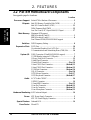
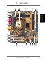
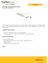
2.2 P4T-EM Motherboard Components
See opposite page for locations.
Location
Processor Support Socket 478 for Pentium 4 Processors ....................................... 3
Chipsets Intel 850 Memory Controller Hub (MCH) ............................... 5
Intel I/O Controller Hub 2 (ICH2) ......................................... 11
2Mbit Firmware Hub (FWH) ................................................. 13
Low Pin Count (LPC) Super Multi-I/O Chipset .................... 17
Main Memory Maximum 2GB support
RIMM Sockets B1 and B2 ....................................................... 1
RIMM Sockets A1 and A2 ....................................................... 6
Dual Channel PC800/PC600 RDRAM support
Switches DSW Frequency Setting ........................................................... 8
Expansion Slots 2 PCI Slots .............................................................................. 18
1 Accelerated Graphics Port (AGP) Slot ................................ 21
1 Communications and Networking Riser (CNR) Slot .......... 16
System I/O 2 IDE Connectors (UltraDMA33/66/100 support)................... 7
1 USB2 Header (supports 2 USB ports)................................... 9
1 Floppy Disk Drive Connector ............................................. 12
1 Smart Card Connector ......................................................... 15
1 Parallel Port Connector ............................................. (Top) 24
1 Serial COM1 Port Connector .............................. (Bottom) 25
1 Serial COM2 Port Connector .............................. (Bottom) 23
2 USB Port Connectors .......................................... (Bottom) 26
1 RJ-45 Connector ........................................................ (Top) 26
1 PS/2 Mouse Connector .............................................. (Top) 27
1 PS/2 Keyboard Connector ................................... (Bottom) 27
Audio AC’97 Audio CODEC ............................................................ 20
1 SPDIF Connector ................................................................ 19
1 Game/MIDI Connector.............................................. (Top) 22
1 Line Out Connector ............................................. (Bottom) 22
1 Line In Connector................................................ (Bottom) 22
1 Line Microphone Connector ............................... (Bottom) 22
Hardware Monitoring ASUS onboard chipset ........................................................... 10
Power ATX Power Supply Connector ................................................. 2
ATX 12V Power Supply Connector ......................................... 4
Special Feature Onboard LED ......................................................................... 14
Form Factor MicroATX
2. FEATURES
MB Components

ASUS P4T-EM User’s Manual 13
2. FEATURES
2. FEATURES
Component Locations
2.2.1 Component Locations
23 5
18
14
23
24
25
26
27
22
1
21
17
13
4 7 86
916 15 12 1011
20
19

14
ASUS P4T-EM User’s Manual
3. HARDWARE SETUP
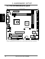
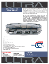
3.1 P4T-EM Motherboard Layout
Grayed components are available only on certain models at the time of purchase.
Motherboard Layout
3. H/W SETUP
RIMMB2 (16/18 bit, 184-pin module)
RIMMB1 (16/18 bit, 184-pin module)
Intel 850
Memory
Controller
Hub (MCH)
®
PS/2KBMS
T: Mouse
B: Keyboard
PANEL
FLOPPY
SECONDARY IDEPRIMARY IDE
Intel I/O
Controller
Hub
(ICH2)
P4T-EM
CR2032 3V
Lithium Cell
CMOS Power
ATX Power Connector
2Mbit
Firmware
Hub
ATX12V
AUX
MAIN_FAN
SW1
USB2
CD1
LED1
COM1
PARALLEL PORT
COM2
MODEM
GAME_AUDIO
Mic
In
Line
Out
Line
In
CPU_FAN
HDDLED
24.4cm (9.60in)
24.4cm (9.6in)
CNR_SLOT
Super
I/O
ASUS
ASIC
SPDIFOUT
OC3
INTEL_FPANEL1
USBPWR
ADN
SMARTCON
Socket 478
Accelerated Graphics Port (AGP)
PCI2
USB1
USB2
Bottom:
RJ-45
Top:
PCI1
J3-
J3+
CHASSIS
IR
SMB
RIMMA
1
(16/18 bit, 184-pin module)
RIMMA2 (16/18 bit, 184-pin module)
Audio
Codec
CLCMOS
J11
J12

15
3. HARDWARE SETUP
ASUS P4T-EM User’s Manual
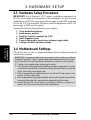
3.2 Layout Contents
Motherboard Settings
1) SW1 p. 17 Motherboard Frequency Settings
2) LED p. 17 Onboard Power Signal
3) SW1 (Switches 1-5) p. 18 CPU External Frequency (CPU/AGP/PCI)
4) USBPWR p. 19 USB Device Wake-up (+5VSB/+5V)
5) ADN p. 19 Onboard Audio (Enable/Disable) (audio models only)
6) J3-J3+, OC3 p. 20 USB2 / CNRUSB Selection (USB2/CNRUSB)
7) J11, J12 p. 20 Intel Front Panel Audio (Enable/Disable)
Memory, CPU and Expansion
1) RIMMA1/A2/B1/B2 p.21 184-Pin System Memory Support
2) CPU p.23 Central Processing Unit (CPU)
3) Heatsink p.24 CPU Heatsink Retention Module Installation
4) PCI1/2 p.27 32-bit PCI Bus Expansion Slots
5) AGP 4x p.29 Accelerated Graphics Port (AGP 4x) Slot
6) CNR p.29 Communications and Networking Riser (CNR) Slot
Connectors
1) PS2KBMS p.30 PS/2 Mouse Connector (6 pin female)
2) PS2KBMS p.30 PS/2 Keyboard Connector (6 pin female)
3) PRINTER p.31 Parallel Port Connector (25 pin female)
4) COM1, COM2 p.31 Serial Port Connector (Two 9 pin male)
5) USB p.31 Universal Serial Bus Ports (Two 4 pin female)
6) RJ-45 p.32
Fast-Ethernet Port Connector (8 pin female) (optional)
8) GAME_AUDIO p.32 Joystick/MIDI Connector (15 pin female) (optional)
9) PRIMARY/SECONDARY IDE p.33 Primary/Secondary IDE Connectors (Two 40-1 pin)
10) FLOPPY p.34 Floppy Disk Drive Connector (34-1pin)
11) MAIN_FAN, CPU_FAN p.34 Fan Connectors (Two 3 pin)
12) USB2 p.35 USB Header (10-1 pin)
13) MODEM, CD_IN, AUX p.35 Internal Audio Connectors (Three 4 pin) (optional)
14) SPDIFOUT p.36 Digital Audio Connector (4-1 pin) (optional)
15) IR p.36
Standard Infrared (SIR) Module Connector (5 pin) (optional)
16) HDLED p.37 IDE Activity LED (2 pin)
17) SMB p.37 System Management Bus Connector (5-1 pin)
18) ATXPWR, ATX12V p.38 Power Supply Connector (20 pin) (4 pin)
19) INTEL_FPANEL1 p.39 Intel Front Panel Audio Connector (10-1 pin) (optional)
20) SMARTCON p.39 ASUS SmartCard Connector (14-1 pin )
21) PLED (PANEL) p.40 System Power LED Lead (3-1 pin)
22) KEYLOCK (PANEL) p.40 Keyboard Lock Switch Lead (2 pin)
23) SPEAKER (PANEL) p.40 System Warning Speaker Connector (4 pin)
24) MLED (PANEL) p.40 System Message LED (2 pin)
25) SMI (PANEL) p.40 System Management Interrupt Switch Lead (2 pin)
26) PWRBTN (PANEL) p.40 ATX Power / Soft-Off Switch Lead (2 pin)
27) RESET (PANEL) p.40 Reset Switch Lead (2 pin)
Layout Contents
3. H/W SETUP

16 ASUS P4T-EM User’s Manual
3. HARDWARE SETUP
Getting Started
3. H/W SETUP
3.4 Motherboard Settings
This section tells you how to change motherboard function settings through the
switches and/or jumpers.
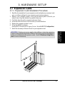
3.3 Hardware Setup Procedure
IMPORTANT: Due to Pentium 4 CPU’s power consumption requirement, an
ATX12V power supply is recommended for this motherboard. For typical system
configurations, an ATX12V power supply that can supply at least 230W and at least
8.5A on the +12V lead is required. For heavily-loaded configurations, an ATX12V
power supply of 300W may be required.
Complete the following steps before using your computer:
1. Check motherboard settings
2. Install memory modules
3. Install the Central Processing Unit (CPU)
4. Install Expansion Cards
5. Connect ribbon cables, panel wires, and power supply cables
6. Configure the BIOS parameter settings
WARNING! Computer motherboards and expansion cards contain very delicate
Integrated Circuit (IC) chips. To protect them against damage from static electric-
ity, you should follow some precautions whenever you work on your computer.
1. Unplug your computer when working on the inside.
2. Use a grounded wrist strap before handling computer components. If you do
not have one, touch both of your hands to a safely grounded object or to a metal
object, such as the power supply case.
3. Hold components by the edges and try not to touch the IC chips, leads or con-
nectors, or other components.
4. Place components on a grounded antistatic pad or on the bag that came with the
component whenever the components are separated from the system.
5. Ensure that the ATX power supply is switched off before you plug in or
remove the ATX power connector on the motherboard.

17
3. HARDWARE SETUP
ASUS P4T-EM User’s Manual
Motherboard Settings
3. H/W SETUP
®
P4T-EM
P4T-EM Onboard LED
ON
OFF
Standby
Power
Powered
Off
®
P4T-EM
P4T-EM DIP Switches
SW1
1. Frequency Selection
2. Frequency Selection
3. Frequency Selection
4. Frequency Selection
5. Frequency Selection.
ON OFF
ON
12345
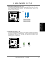
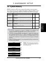
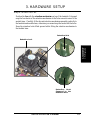
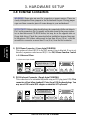
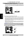
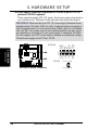
2) Onboard Power Signal (LED)
The board LED illuminates if power is connected and operating okay and when
the system is in soft-off or suspend mode. Adding or removing devices is not
advisable when the LED is lit, since the user risks electrical shock and/or
disabling system configuration.
1) Motherboard Frequency Settings (SW1)
The motherboard frequency is adjusted through the DIP switches. The white
block represents the switch’s position. The illustration below shows all the
switches in the OFF position.

18 ASUS P4T-EM User’s Manual
3. HARDWARE SETUP
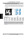
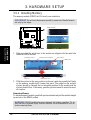
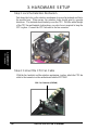
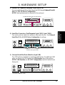
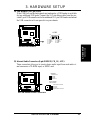
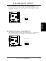
3) CPU External Frequency Selection (SW1 Switches 1-5)
This option tells the clock generator what frequency to send to the CPU, DRAM,
and the PCI bus. This allows the selection of the CPU’s External frequency (or
BUS Clock). The BUS Clock multiplied by the Frequency Multiple equals the
CPU’s Internal frequency (the advertised CPU speed). The system default is set
at 100/66/ 33.
®
P4T-EM
P4T-EM CPU
External Frequency Selection
CPU
AGP
PCI
SW1
100.0MHz
66.0MHz
33.0MHz
103.0MHz
68.0MHz
34.0MHz
105.0MHz
70.0MHz
35.0MHz
110.0MHz
73.0MHz
36.0MHz
CPU
AGP
PCI
ON
12345
ON
12345
ON
12345
ON
12345
Default
Setting
Motherboard Settings
3. H/W SETUP
WARNING! Set the CPU frequency only to the recommended settings.
Frequencies other than the recommended CPU bus frequencies are not guaranteed
to be stable. Overclocking the processor is not recommended. It may result in a
slower speed.
Frequency Table DSW
CPU AGP PCI 1 2 3 4 5
100 66 33 [ON] [OFF] [ON] [ON] [ON]
103 68 34 [OFF] [OFF] [ON] [ON] [ON]
105 70 35 [ON] [ON] [OFF] [ON] [ON]
110 73 36 [ON] [OFF] [OFF] [ON] [ON]

19
3. HARDWARE SETUP
ASUS P4T-EM User’s Manual
Motherboard Settings
3. H/W SETUP
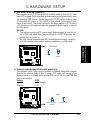
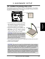
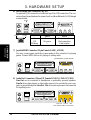
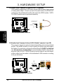
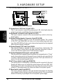
4) USB Device Wake-up (USBPWR)
The jumpers are set to +5V as the default to allow wake up from the S1 sleep
state (CPU stopped; RAM refreshed; system running in low power mode) using
the connected USB devices. Set the jumpers to +5VSB to allow wake up from
S3 sleep state (no power to CPU; RAM in slow refresh; power supply in re-
duced power mode). The default setting for the three jumpers is 2-3 to select
+5V (because not all computers have the appropriate power supply to support
the other mode).
NOTES:
1. This feature requires an ATX power supply that can supply at least 2A on
the +5VSB lead when these jumpers are set to +5VSB. Otherwise, the
system does not power up.
2. The total current consumed must NOT exceed the power supply capability
(+5VSB) whether under normal working conditions or in sleep mode.
5) Onboard Audio Setting (ADN) (audio models only)
The onboard Audio Codec may be enabled or disabled using these jumpers.
Disable the onboard Audio Codec if using a PCI audio card on any of the
expansion slots or a primary audio/modem CNR on a CNR slot (see CNR Slot
later in this section).
Setting ADN
Enable [1-2] (default)
Disable [2-3]
®
P4T-EM
P4T-EM AUDIO Setting
ENABLE AUDIO DISABLE AUDIO
ADN
2
3
1
2
(Default)
®
P4T-EM
P4T-EM USB Device Wake Up
USBPWR
+5V
1
2
+5VSB
2
3
(Default)

20 ASUS P4T-EM User’s Manual
3. HARDWARE SETUP
Motherboard Settings
3. H/W SETUP
®
P4T-EM
P4T-EM CNR/USB Selection
CNRUSB
USB2
(Default)
OC3
1
2
J3-
J3+
2
3
OC3
J3-
J3+
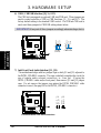
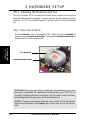
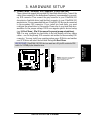
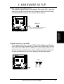
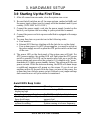
6) USB2 / CNRUSB Selection (J3-J3+, OC3)
The CNR slot can support an optional USB hub CNR card. Three jumpers are
used to control selection of USB or CNR functions: J3-, J3+ and OC3. The
factory default setting is for standard USB2 control. If a USB hub CNR card is
used, reset these jumpers to CNRUSB setting shown below.
IMPORTANT! Always set all three jumpers accordingly when selecting a device.
®
P4T-EM
P4T-EM Internal Line Out Connectors
J11 J12
LAP_LT
LAP_LTT
LAP_RT
LAP_RTT
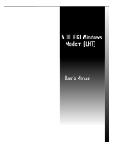
7) Intel Front Panel Audio Selection (J11, J12)
The motherboard ships with two jumper caps on both J11 and J12, adjacent to
the INTEL_FPANEL1 connector. The caps-on default completes the circuit for
use of regular audio external connectors, ie.: Line_out. If using the
INTEL_FPANEL1 cable and/or front panel, then remove J11 and J12 jumper
caps. Do not remove the jumper caps unless the INTEL_FPANEL1 cable
connector is used. (See page 39 for the INTEL_FPANEL1 connector.)
Page is loading ...
Page is loading ...
Page is loading ...
Page is loading ...
Page is loading ...
Page is loading ...
Page is loading ...
Page is loading ...
Page is loading ...
Page is loading ...
Page is loading ...
Page is loading ...
Page is loading ...
Page is loading ...
Page is loading ...
Page is loading ...
Page is loading ...
Page is loading ...
Page is loading ...
Page is loading ...
Page is loading ...
Page is loading ...
Page is loading ...
Page is loading ...
Page is loading ...
Page is loading ...
Page is loading ...
Page is loading ...
Page is loading ...
Page is loading ...
Page is loading ...
Page is loading ...
Page is loading ...
Page is loading ...
Page is loading ...
Page is loading ...
Page is loading ...
Page is loading ...
Page is loading ...
Page is loading ...
Page is loading ...
Page is loading ...
Page is loading ...
Page is loading ...
Page is loading ...
Page is loading ...
Page is loading ...
Page is loading ...
Page is loading ...
Page is loading ...
Page is loading ...
Page is loading ...
Page is loading ...
Page is loading ...
Page is loading ...
Page is loading ...
Page is loading ...
Page is loading ...
Page is loading ...
Page is loading ...
Page is loading ...
Page is loading ...
Page is loading ...
Page is loading ...
Page is loading ...
Page is loading ...
Page is loading ...
Page is loading ...
Page is loading ...
Page is loading ...
Page is loading ...
Page is loading ...
Page is loading ...
Page is loading ...
Page is loading ...
Page is loading ...
-
 1
1
-
 2
2
-
 3
3
-
 4
4
-
 5
5
-
 6
6
-
 7
7
-
 8
8
-
 9
9
-
 10
10
-
 11
11
-
 12
12
-
 13
13
-
 14
14
-
 15
15
-
 16
16
-
 17
17
-
 18
18
-
 19
19
-
 20
20
-
 21
21
-
 22
22
-
 23
23
-
 24
24
-
 25
25
-
 26
26
-
 27
27
-
 28
28
-
 29
29
-
 30
30
-
 31
31
-
 32
32
-
 33
33
-
 34
34
-
 35
35
-
 36
36
-
 37
37
-
 38
38
-
 39
39
-
 40
40
-
 41
41
-
 42
42
-
 43
43
-
 44
44
-
 45
45
-
 46
46
-
 47
47
-
 48
48
-
 49
49
-
 50
50
-
 51
51
-
 52
52
-
 53
53
-
 54
54
-
 55
55
-
 56
56
-
 57
57
-
 58
58
-
 59
59
-
 60
60
-
 61
61
-
 62
62
-
 63
63
-
 64
64
-
 65
65
-
 66
66
-
 67
67
-
 68
68
-
 69
69
-
 70
70
-
 71
71
-
 72
72
-
 73
73
-
 74
74
-
 75
75
-
 76
76
-
 77
77
-
 78
78
-
 79
79
-
 80
80
-
 81
81
-
 82
82
-
 83
83
-
 84
84
-
 85
85
-
 86
86
-
 87
87
-
 88
88
-
 89
89
-
 90
90
-
 91
91
-
 92
92
-
 93
93
-
 94
94
-
 95
95
-
 96
96


Ask a question and I''ll find the answer in the document
Finding information in a document is now easier with AI
Related papers
Other documents
-
Canyon CNR-USBHUB5N Datasheet
-
 StarTech.com USBPLATEB Datasheet
-
Gigabyte GA-8ITML User manual
-
Gigabyte GA-8ITXE User manual
-
-
Gigabyte GA-8ITX3 User manual
-
 Ultra Products ULT31106 User manual
-
ActionTec IS560SKV User manual
-
BTC 5126H User manual
-
 Windows Marketplace V.90 User manual


