Chicago Electric 66619 User manual
- Category
- Power generators
- Type
- User manual

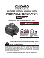
800 RATED WATTS/900 MAXIMUM WATTS
PORTABLE GENERATOR
Model
66619
OPERATION AND SERVICE INSTRUCTIONS
DANGER
Using a generator indoors CAN KILL YOU IN
MINUTES.
Generator exhaust contains carbon monoxide. This
is a poison you cannot see or smell.
NEVER use inside a home
or garage, EVEN IF doors
and windows are open.
Only use OUTSIDE
and far away from
windows, doors, and
vents.
Visit our website at: http://www.harborfreight.com
Read this material before using this product.
Failure to do so can result in serious injury.
SAVE THIS MANUAL.
Copyright
©
2008 by Harbor Freight Tools
®
. All rights reserved. No portion of this manual or any artwork
contained herein may be reproduced in any shape or form without the express written consent of
Harbor Freight Tools. Diagrams within this manual may not be drawn proportionally. Due to continuing
improvements, actual product may differ slightly from the product described herein. Tools required for
assembly and service may not be included.
For technical questions or replacement parts, please call 1-800-444-3353.
Revised Manual 10e
Portable Generator
ITEM 66619
50:1 Unleaded Gasoline and 2 Stroke Oil mixture.
Fuel Capacity: 1.1 Gallons
CARB and EPA Certied
● 3600 RPM ● Recoil Start, 2HP, Two Stroke Engine ● Output: 120 V~ / 60 Hz
800 Rated Watts/900 Max Watts

Page 2For technical questions, please call 1-800-444-3353.SKU 66619
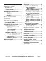
CONTENTS
IMPORTANT SAFETY
INFORMATION .................................3
AC APPLICATIONS ................................. 7
GENERATOR PRECAUTIONS ...........7
SET UP: .............................................. 7
OPERATION: ..................................... 8
SERVICE: ........................................... 8
BASIC SPECIFICATIONS ..................8
UNPACKING .......................................8
THIS UNIT CAN POWER THE
FOLLOWING ITEMS ........................9
OPERATING INSTRUCTIONS ...........9
STARTING THE ENGINE ........................ 9
CHECKING AND FILLING THE
FUEL TANK: .................................... 9
START PROCEDURE: ..................... 10
BREAK-IN PERIOD: .........................11
EQUIPMENT OPERATION .................... 12
LOAD AND CIRCUIT BREAKER: ... 12
CALCULATING POWER DRAW: .... 12
AC APPLICATION: .......................... 12
GENERATOR SHUT OFF: ............... 12
SPECIFICATIONS .............................14
SERVICING .......................................14
MAINTENANCE PROCEDURES .......... 14
AIR FILTER ELEMENT
MAINTENANCE: ........................... 14
SPARK PLUG MAINTENANCE: ...... 15
CLEANING, MAINTENANCE, AND
LUBRICATION SCHEDULE: ENGINE 15
AFTER INITIAL 25 OPERATION
HOURS: ......................................... 15
EVERY 25 OPERATION HOURS
THEREAFTER: .............................. 15
EVERY 50 OPERATION HOURS: ... 15
EVERY 100 OPERATION HOURS: . 15
EVERY 300 OPERATION HOURS: . 15
STORAGE ............................................. 16
MAINTENANCE AND CLEANING
SCHEDULE: GENERATOR ................ 16
AFTER EVERY USE: ....................... 16
TROUBLESHOOTING - ENGINE .....17
TROUBLESHOOTING -
GENERATOR UNIT ........................19
PARTS LIST ......................................20
ASSEMBLY DIAGRAM .....................21
WIRING DIAGRAM ...........................23
LIMITED 1 YEAR / 90 DAY
WARRANTY ...................................24
EMISSION CONTROL SYSTEM
WARRANTY ...................................24

Page 3For technical questions, please call 1-800-444-3353.SKU 66619
SAVE THIS MANUAL
Keep this manual for the safety warnings
and precautions, assembly, operating,
inspection, maintenance and cleaning
procedures. Write the product’s serial number
in the back of the manual (or month and year
of purchase if product has no number). Keep
this manual and the receipt in a safe and dry
place for future reference.
IMPORTANT SAFETY
INFORMATION
In this manual, on the labeling, and
all other information provided with
this product:
This is the safety alert
symbol. It is used to alert
you to potential personal
injury hazards. Obey all
safety messages that follow
this symbol to avoid possible
injury or death.
DANGER indicates a
hazardous situation
which, if not avoided, will result
in death or serious injury.
WARNING indicates a
hazardous situation
which, if not avoided, could
result in death or serious injury.
CAUTION, used with
the safety alert
symbol, indicates a hazardous
situation which, if not avoided,
could result in minor or moderate
injury.
NOTICE is used to
address practices not
related to personal injury.
CAUTION, without the
safety alert symbol, is
used to address practices not
related to personal injury.
WARNING! Read all instructions.
Failure to follow all instructions
listed below may result in re,
serious injury and/or DEATH. The
warnings and precautions discussed
in this manual cannot cover all
possible conditions and situations that
may occur. It must be understood
by the operator that common sense
and caution are factors which cannot
be built into this product, but must be
supplied by the operator.
SAVE THESE INSTRUCTIONS
SET UP PRECAUTIONS
1.
and potentially explosive. Use proper
fuel storage and handling procedures.
materials nearby.
2.
extinguishers nearby.
Operation of this equipment may create 3.
vegetation.
agencies for laws or regulations relating
4.
ventilated surface.
5.
Use only oil and fuel recommended 6.
manual.

Page 4For technical questions, please call 1-800-444-3353.SKU 66619
OPERATING PRECAUTIONS
1. CARBON MONOXIDE
HAZARD
Using a generator indoors
CAN KILL YOU IN MINUTES.
Generator exhaust contains
carbon monoxide. This is a poison you
cannot see or smell.
NEVER use inside a home or garage,
EVEN IF doors and windows are open.
Only use OUTSIDE and far away from
windows, doors, and vents.
Keep all safety guards in place and in 2.
proper working order at all times.
3.
near the Generator when it is running.
Do not lean or reach over the Generator
when the machine is running.
Keep all people (except the operator) a 4.
minimum of six feet from the Generator
during operation.
Do not transport the Generator with the 5.
Engine running.
Do not sit or stand on this machine.6.
Do not tilt the machine while the Engine 7.
is running.
Do not leave the Generator unattended 8.
when it is running. Turn off the Engine
before leaving the area.
9.
hearing protection, and heavy duty work
gloves during use.
People with pacemakers should 10.
consult their physician(s) before use.
to a heart pacemaker could cause
pacemaker interference or pacemaker
failure. Caution is necessary when near
the engine’s magneto or recoil starter.
Use only accessories that are 11.
recommended by Harbor Freight Tools
for your model. Accessories that may
be suitable for one piece of equipment
may become hazardous when used on
another piece of equipment.
Do not operate in explosive 12.
atmospheres, such as in the presence
the dust or fumes.
Stay alert, watch what you are doing 13.
and use common sense when operating
this piece of equipment. Do not use
this piece of equipment while tired or
medication.
Do not overreach. Keep proper footing 14.
and balance at all times. This enables
better control of the equipment in
unexpected situations.
Dress properly. Do not wear loose 15.
clothing or jewelry. Keep hair, clothing
and gloves away from moving parts.
Loose clothes, jewelry or long hair can
be caught in moving parts.
Parts, especially exhaust system 16.
components, get very hot during use.
Stay clear of hot parts.
Do not cover the Generator during 17.
operation.
REV 10b

Page 5For technical questions, please call 1-800-444-3353.SKU 66619
Keep the equipment, Engine, and 18.
surrounding area clean at all times.
Use the equipment, accessories, etc., in 19.
accordance with these instructions and
in the manner intended for the particular
type of equipment, taking into account
the working conditions and the work to
be performed. Use of the equipment for
operations different from those intended
could result in a hazardous situation.
Do not operate the equipment with 20.
known leaks in the Engine’s fuel system.
This product contains or, when used, 21.
produces a chemical known to the State
of California to cause cancer and birth
defects or other reproductive harm.
(California Health & Safety Code §
25249.5, et seq.)
When spills of fuel or oil occur, they must 22.
be cleaned up immediately. Dispose
any local, state, or federal codes and
ventilated, covered, metal container.
Before use, check for misalignment 23.
or binding of moving parts, breakage
of parts, and any other condition that
may affect the equipment’s operation.
If damaged, have the equipment
serviced before using. Many accidents
are caused by poorly maintained
equipment.
Use the correct equipment for the 24.
application. Do not modify the
equipment and do not use the equipment
for a purpose for which it is not intended.
SERVICE PRECAUTIONS
Before service, maintenance, or 1.
cleaning:
Turn the Power Switch of the Engine a.
to its “OFF” position.
Allow the Engine to completely cool.b.
Then, remove the Spark Plug.c.
Keep all safety guards in place and in 2.
proper working order. Safety guards
guards, and heat shields, among other
guards.
Do not alter or adjust any part of the 3.
equipment or its Engine that is sealed by
the manufacturer or distributor. Only a
parts that may increase or decrease
governed Engine speed.
4.
heavy duty work gloves during service.
Maintain labels and nameplates on 5.
the equipment. These carry important
information. If unreadable or missing,
contact Harbor Freight Tools for a
replacement.
Have the equipment serviced by a 6.
identical replacement parts. This will
ensure that the safety of the equipment
is maintained. Do not attempt any
service or maintenance procedures
not explained in this manual or any
procedures that you are uncertain about
your ability to perform safely or correctly.
Store equipment out of the reach of 7.
children.
Follow scheduled Engine and equipment 8.
maintenance.
Refueling Precautions:9.

Page 6For technical questions, please call 1-800-444-3353.SKU 66619
or other sources of ignition around the
equipment, especially when refuelling.
engine is running or hot.
a little room for the fuel to expand as
needed.
CAUTION: 10. This generator is not
intended to power sensitive electronic
equipment
*
without the addition of an
appropriate line conditioner and surge
protector (both not included). Sensitive
electronic equipment should be operated
on approved inverter type generators or
pure sine wave generators.
If the plugged in product operates
abnormally or unusually slow,
immediately stop using the generator
as a power source. Always read and
adhere to the instruction manual of the
product to be powered, to make sure that
by a portable generator.
Note: When using a generator to
provide home standby electricity, a
transfer switch (sold separately) is
needed to prevent back feeding power
into the utility line.
Connections for standby power to a
building electrical system must be made
must isolate the generator power from
utility power, and must comply with all
applicable laws and electrical codes.
WARNING: Improper connections to
a building electrical system can allow
electrical current from the generator
to backfeed into the utility lines. Such
backfeed may electrocute utility
company workers or others who contact
the lines during a power outage, and the
generator may explode, burn, or cause
electrician.
* Sensitive electronic equipment
includes, but is not limited to, audio/
video equipment, some television sets,
computers, and printers.

Page 7For technical questions, please call 1-800-444-3353.SKU 66619
AC APPLICATIONS
Before connecting an appliance or 1.
power cord to the generator: Make sure
that it is in good working order. Faulty
appliances or power cords can create a
potential for electrical shock.
If an appliance begins to operate 2.
abnormally, becomes sluggish or
stops suddenly, turn it off immediately.
Disconnect the appliance, and determine
whether the problem is the appliance, or
if the rated load capacity of the generator
has been exceeded.
Make sure that the electrical rating of 3.
the tool or appliance does not exceed
that of the generator. Never exceed the
maximum power rating of the generator.
Power levels between rated and
maximum may be used for no more than
30 minutes.
Substantial overloading will open the 4.
circuit breaker. Exceeding the time limit
for maximum power operation or slightly
overloading the generator may not switch
the circuit breaker or circuit protector
OFF, but will shorten the service life of
the generator.
SAVE THESE
INSTRUCTIONS.
GENERATOR PRECAUTIONS
Set Up:
Do not connect the Generator directly 1.
into a home’s utility electrical line. Do
not plug this Generator into an outlet
in the home. Connecting a generator
directly to a utility power supply can
or injure utility workers working on the
lines.
All connections and conduits from 2.
the Generator to the load must only
be installed by trained and licensed
electricians, and in compliance with
all relevant local, state, and federal
electrical codes and standards, and
other regulations where applicable.
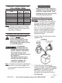
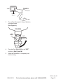
3.
in accordance with all relevant electrical
codes and standards before operation.
used to connect the ground terminal
of the Generator to a grounding rod.
A wire that is too thin may not provide
capacity to be an adequate ground
path.
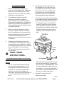
FIGURE A
10 GAUGE
GROUND
WIRE
GROUNDING ROD
The other end of the ground wire must
be securely fastened to an approved
ground source. (See Figure A.) Refer
to local regulations for ground source
information. If unsure of regulations or
procedures, obtain assistance from a
Insulate all connections and 4.
disconnected wires.
REV 09c

Page 8For technical questions, please call 1-800-444-3353.SKU 66619
REV 09c
Connect the Generator only to a 5.
load or electrical system (120 V~)
that is compatible with the electrical
characteristics and rated capacities of
the Generator.
6.
ventilated, dry area, away from building
air intakes. The Generator should be
protected from direct exposure to rain
and snow. Do not set up the Generator
on a conductive surface such as a metal
deck.
Operation:
Do not attempt to connect or disconnect 1.
load connections while standing in water,
or on wet or soggy ground.
Do not touch electrically energized parts 2.
of the Generator and interconnecting
cables or conductors with any part of
conductive object.
3.
Do not overload the Generator. 4.
electrical cords, in addition to Generator
and appliance damage.
Service:
Keep all electrical equipment clean
and dry. Replace any wiring where the
insulation is cracked, cut, abraded, or
otherwise degraded. Replace terminals
that are worn, discolored, or corroded.
Keep terminals clean and tight.
BASIC SPECIFICATIONS
Fuel
Required
Mixture
(50:1)
50 Parts 89+ octane
unleaded gasoline
mixed with 1 part
Capacity 1.1 Gallons
Note:
TECHNICAL ENGINE SPECIFICATIONS
chart in this manual.
The emission control system for this
engine is warranted for standards set by the
U.S. Environmental Protection Agency and
by the California Air Resources Board (also
known as CARB). For warranty information,
refer to the last pages of this manual.
At high altitudes, the engine’s carburetor,
governor, and any other parts that control
altitude use and to prevent damage to the
engine and any other devices used with this
product.
UNPACKING
When unpacking, make sure that the
item is intact and undamaged. If any parts
are missing or broken, please call Harbor
possible.

Page 9For technical questions, please call 1-800-444-3353.SKU 66619
THIS UNIT CAN POWER THE
FOLLOWING ITEMS
ITEM
RUNNING
WATTS
START-UP
WATTS
Ten 75 Watt Light Bulbs 750
1/4HP Compressor 600 900
1/6HP Motor 500 800
400 600
Mini Refrigerator 400 700
15 Amp Battery Charger 380
String Trimmer 350 500
Table/Box Fan 200 300
Radio 50
NOTE: Wattages listed above are estimates
for that type of equipment only. Check
nameplate wattages on all loads before
connecting to Generator.
OPERATING INSTRUCTIONS
Read the ENTIRE IMPORTANT
SAFETY INFORMATION
section at the beginning of this
manual including all text under
subheadings therein before set up
or use of this product.
TO PREVENT
SERIOUS INJURY:
Operate only with proper spark
arrestor installed. Operation of
this equipment may create
sparks that can start res around
dry vegetation.
The operator should contact
local re agencies for laws or
regulations relating to re
prevention requirements.
Note: For additional information regarding the
parts listed in the following pages, refer
to the Assembly Diagram near the end of
this manual.
Starting the Engine
Inspect the Generator looking for
damaged, loose, and missing parts
before set up and starting. If any
problems are found, do not use the
unit until properly repaired.
Checking and Filling The Fuel Tank:
CAUTION! Your Warranty is VOID if the
the proper mixture (50:1) of unleaded
gasoline and 2-cycle oil before each
use. Before each use, check the fuel
level. Do not run the Engine with an
mixture. Running the Engine with an
improper mixture WILL permanently
damage the Engine.
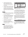
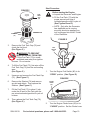
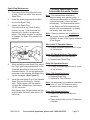
The Fuel Tank (73) holds approximately 1.
1 gallon of fuel.
FIGURE B
1 GALLON
UNLEADED
GASOLINE
2.5 FLUID OUNCES
2-CYCLE OIL
APPROVED
CONTAINER
2. To obtain the proper gasoline and
uid ounces
of 2-cycle oil with 1 gallon of unleaded
gasoline into an approved container.
Then slowly shake the container to
(See Figure B.)
REV 10b

Page 10For technical questions, please call 1-800-444-3353.SKU 66619
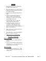
FIGURE C
FUEL
TANK
CAP
(76)
STRAINER
(74)
3. Remove the Fuel Tank Cap (76) and
check the fuel level.
(See Figure C.)
WARNING! TO PREVENT
SERIOUS INJURY FROM FIRE:
ventilated area away from ignition
sources. Do not smoke.
4.
Fuel Tank Cap (76) and the surrounding
area.
(See Figure C.)
Unscrew, and remove the Fuel Tank Cap 5.
(76). (See Figure C.)
Remove the Strainer (74) and remove 6.
any dirt and debris. Then replace the
Strainer. (See Figure C.)
Fill the Fuel Tank (73) to about 1 inch 7.
mixture.
Then replace the Fuel Tank Cap (76). 8.
(See Figure C.)
Start Procedure:
Before starting the Engine:
Inspect the Generator and Engine.a.
Fill the Fuel Tank (73) with the b.
proper amount and type of
(See Figures B and C.)
NOTE: Only after the Generator c.
has stabilized and is running
smoothly should an appliance or
tool be plugged into the AC Outlet
of the Generator.
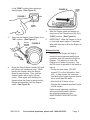
FIGURE D
FUEL
SWITCH
(80)
“OPEN”
1. Turn the Engine Fuel Switch (80) to its
“OPEN” position. (See Figure D.)
FIGURE E
“CHOKE”
“RUN”
CHOKE
LEVER
(82)
2. Turn the Engine Choke Lever (82) to its
“CHOKE” position. Set the Choke Lever

Page 11For technical questions, please call 1-800-444-3353.SKU 66619
in the “RUN” position when starting a
warm Engine. (See Figure E.)
FIGURE F
“ON”
POWER
SWITCH
3. Then turn the Engine Power Switch to its
“ON” position. (See Figure F.)
FIGURE G
RECOIL
STARTER
HANDLE
(42)
4. Grasp the Recoil Starter Handle (42) and
pull slowly until resistance is felt. While
holding the Handle, allow the Starter
Rope to rewind slowly. Then, pull the
Starter Handle with a rapid, full arm
stroke. Once again while holding the
Handle, allow the Rope to rewind slowly.
Repeat as necessary, until the Engine
starts. (See Figure G.)
FIGURE H
CHOKE
LEVER
(82)
“RUN”
“CHOKE”
5. After the Engine starts and warms up,
slowly move the Choke Lever (82) to its
“RUN” position. (See Figure H.)
IMPORTANT: Allow the Engine to run at 6.
no load until warm (approx. 3 minutes)
stabilize.
Break-in Period:
1.
ensure proper equipment and Engine
operation, and will extend the Engine’s
lifespan. The warranty is void if the
Engine is not broken in properly. The
period.
During this time frame, DO NOT
exceed 75% of the Generator’s load
limit. In other words, the maximum
be no more than 600 watts.
oil fuel mixture.
Under normal operating conditions
subsequent maintenance follows
the schedule explained in the
MAINTENANCE AND SERVICING
section.

Page 12For technical questions, please call 1-800-444-3353.SKU 66619
Equipment Operation
Load And Circuit Breaker:
The total combined load through the 1.
outlet on the Generator must not exceed
the rated maximum power (800 watts) of
the unit.
FIGURE I
RESET
OFF
CIRCUIT
BREAKER
2. Always reduce the load if the AC Circuit
Breaker turns off. Once the load is
reduced, press the Breaker to reset the
Generator and continue operation.
(See Figure I.)
Calculating Power Draw:
Power draw can be calculated by
multiplying volts and amps. The
resulting number is wattage.
Never exceed the rated maximum
wattage (800) for the Generator or
outlet.
Refer to appliance/tool owner’s
manuals to determine the wattage of
electrical load devices.
Long power cords and extension cords
draw additional power. Keep cord
length at a minimum.
AC Application:
Allow the Engine to run at no load until 1.
warm (approx. 3 minutes) after each
FIGURE J
2. Plug the power cord of the 120 volt
appliance/tool into the 120 volt AC Outlet
on the Generator. (See Figure J.)
NOTE: Do not allow the generator 3.
to completely run out of fuel with
devices attached. A generator’s
output may sharply spike as it runs
out of fuel, causing damage to
attached devices.
FIGURE K
3.
unplug its power cord from the AC Outlet
on the Generator. (See Figure K.)
Generator Shut Off:
Remove all electrical load devices from 1.
the Generator. (See Figure K.)
Allow the Engine to run for approximately 2.
3 minutes with no electrical load.
REV 10e

Page 13For technical questions, please call 1-800-444-3353.SKU 66619
REV 09c, 09g, 09k
FIGURE L
“OFF”
POWER
SWITCH
3. Turn off the Generator’s Power Switch to
stop the Engine.
(See Figure L.)
FIGURE M
“OFF”
FUEL
SWITCH
(80)
4. Turn the Fuel Switch (80) to its “OFF”
position. (See Figure M.)
Allow the Generator to completely cool 5.
before storing.

Page 14For technical questions, please call 1-800-444-3353.SKU 66619
SPECIFICATIONS
Engine Type
Horizontal Shaft.
Engine Starter Type Recoil Starter
Engine Power Rating 2.0 H.P.
Displacement 63cc
Required Fuel Mixture (50:1)
50 Parts 89+ Octane Unleaded
Fuel Tank Capacity 1.1 Gallons
Spark Plug Gap
Spark Plug Arrestor Present No
Engine Run Time
with Full Tank at
50% Load
Approximately 5 Hours
AC Receptacle
Type
60 Hz with 7 AMP Circuit Breaker
Generator
Rated Output
Power
800 Watts
Generator
Maximum
Output Power
900 Watts
Accessories
SERVICING
TO PREVENT
SERIOUS INJURY
FROM ACCIDENTAL STARTING:
Turn the Power Switch of the
Engine to its “OFF” position, wait
for the Engine to cool, and
remove the Spark Plug wire
before performing any
inspection, maintenance, or
cleaning procedures.
TO PREVENT
SERIOUS INJURY
FROM EQUIPMENT FAILURE:
Do not use damaged equipment.
If abnormal noise, vibration, or
excess smoking occurs, have the
problem corrected before further
use.
Maintenance Procedures
Many maintenance procedures,
including those not detailed in this
manual, will need to be performed
by a qualied technician for
safety. If you have any doubts
about your ability to safely service
the equipment or Engine, have a
qualied technician service the
equipment instead.
Note: Warranty is void if proper maintenance
and servicing procedures are not
followed.
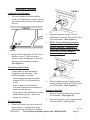
Air Filter Element Maintenance:
A
B
C D
E
F
FIGURE N
1. Wipe off the Air Cleaner Cover. Then
remove the Cover. (See Figure N.)
Remove the Air Filter Element.2.
Wash the Air Filter Element in warm 3.
water and mild detergent several times.
Rinse. Squeeze out excess water and
allow it to dry completely. Soak the Filter
the excess oil.
Install the new Air Filter Element or the 4.
cleaned Filter. Secure the Air Cleaner
Cover before use.
REV 09k

Page 15For technical questions, please call 1-800-444-3353.SKU 66619
Spark Plug Maintenance:
Disconnect Spark Plug Wire from end 1.
of plug. Clean out debris from around
Spark Plug.
Using the spark plug wrench provided, 2.
remove the Spark Plug.
Inspect the Spark Plug: 3.
If the electrode is oily, clean it using
a clean, dry rag. If the electrode has
deposits on it, polish it using emery
paper. If the white insulator is cracked
or chipped, the Spark Plug needs to be
replaced.
FIGURE O
0.028” ~ 0.031”
4. When installing a new Spark Plug, adjust
illustration below. Do not pry against the
electrode or the insulator, the Spark Plug
can be damaged. (See Figure O.)
Install the new Spark Plug or the cleaned 5.
contacts the cylinder head, then about
plug contacts the head, then about 1/16
turn more.
Cleaning, Maintenance, and
Lubrication Schedule: Engine
Note: This maintenance schedule is
intended solely as a general guide. If
performance decreases or if the Engine
operates unusually, check systems
immediately. The maintenance needs
of this Engine will differ depending on
factors such as temperature, air quality,
fuel quality, and other factors.
Note: These procedures are in addition to
the regular checks and maintenance
explained as part of the regular operation
of the Engine.
After Initial 25 Operation Hours:
a.
oil fuel mixture.
Every 25 Operation Hours Thereafter:
Clean/replace Air Filter Element.a.
Inspect/clean Spark Plug.b.
Every 50 Operation Hours:
a.
oil fuel mixture.
Every 100 Operation Hours:
Replace Spark Plug.a.
Replace Air Filter Element.b.
Note: All maintenance procedures scheduled
for 25, 50, and 100 operation hours
should be performed at least yearly.
Every 300 Operation Hours:
Clean Fuel Tank and Carburetor a.
assembly.
b.
Chamber.

Page 16For technical questions, please call 1-800-444-3353.SKU 66619
Storage
Wait for the Engine to cool, then clean 1.
the Engine with a clean cloth.
When the equipment is to remain idle for 2.
longer than 20 days, prepare the Engine
for storage as follows:
Empty the Fuel Tank and drain all fuel a.
lines.
Clean out area around Spark Plug. b.
Remove Spark Plug and pour one
tablespoon of engine oil into Cylinder
through Spark Plug hole.
Reinstall Spark Plug, but leave the c.
Spark Plug Wire disconnected.
Pull Starter Handle to distribute oil d.
in Cylinder. Stop after one or two
revolutions when you feel the Piston
start the compression stroke (when you
start to feel resistance).
Apply a thin coat of rust preventive oil to 3.
all uncoated metal parts.
4.
area out of reach of children.
Maintenance and Cleaning
Schedule: Generator
Before Every Use:
Check to make sure all bolts and nuts a.
are tight.
Check for any damage to the Generator. b.
If damaged, do not use until repaired by
After Every Use:
Allow the unit to completely cool. Then a.
clean the exterior of the Generator with
a clean cloth.

Page 17For technical questions, please call 1-800-444-3353.SKU 66619
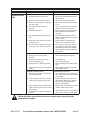
TROUBLESHOOTING - ENGINE
Problem Possible Causes Probable Solutions
Engine will not
start
FUEL RELATED:
Improper gasoline/2 cycle oil mix.1.
No fuel in tank or fuel valve closed.2.
Choke not in start position, especially 3.
with cold engine.
Low quality or deteriorated, old 4.
gasoline.
Carburetor not primed. 5.
Dirty fuel passageways blocking fuel 6.
Carburetor needle stuck. Fuel can be 7.
smelled in the air.
Too much fuel in chamber. This can be 8.
caused by a stuck carburetor needle.
FUEL RELATED:
Mix 50 parts unleaded gasoline with 1 1.
Fill fuel tank and open fuel valve.2.
Move choke to start position if engine 3.
is cold.
Use only fresh 89+ octane unleaded 4.
Prime carburetor by pressing priming 5.
equipped).
Clean out passageways using fuel 6.
additive. Heavy deposits may require
further cleaning.
7.
chamber with screwdriver handle.
Turn choke to run position. Remove 8.
spark plug and pull the start handle
several times to air out the chamber.
Reinstall spark plug and set choke to
start position.
IGNITION (SPARK) RELATED:
Spark plug wire not connected 1.
securely.
Spark plug electrode wet or dirty.2.
Incorrect spark plug gap.3.
Spark plug wire or spark plug broken.4.
Incorrect spark timing or faulty ignition 5.
system.
IGNITION (SPARK) RELATED:
Connect spark plug wire properly. 1.
Clean spark plug.2.
Correct spark plug gap.3.
Replace spark plug wire and/or spark 4.
plug.
5.
repair ignition system.
COMPRESSION RELATED:
Cylinder not lubricated. Problem after 1.
long storage periods.
Loose or broken spark plug. (Hissing 2.
noise will occur when trying to start.)
Loose cylinder head or damaged head 3.
gasket. (Hissing noise will occur when
trying to start.)
Engine valves or tappets misadjusted 4.
or stuck.
COMPRESSION RELATED:
Pour tablespoon of oil into spark plug 1.
hole. Crank engine a few times and try
to start again.
Tighten spark plug. If that does not 2.
work, replace spark plug. If problem
persists, may have head gasket
problem, see #3 below.
Tighten head. If that does not remedy 3.
problem, replace head gasket.
Adjust valve clearance. If that does not 4.
work, clean or replace valves/tappets.
Follow all safety precautions whenever diagnosing or servicing the
equipment or engine.

Page 18For technical questions, please call 1-800-444-3353.SKU 66619
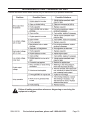
TROUBLESHOOTING - ENGINE
Problem Possible Causes Probable Solutions
Engine misres
Spark plug wire loose.1.
Incorrect spark plug gap or damaged 2.
spark plug.
Defective spark plug wire.3.
Old or low quality gasoline. 4.
Incorrect compression.5.
Check wire connections.1.
2.
Replace spark plug wire.3.
Use only fresh 89+ octane unleaded 4.
Diagnose and repair compression. (Use 5.
Engine will not start: COMPRESSION
RELATED section.)
Engine stops
suddenly
Fuel tank empty or full of impure or low 1.
quality gasoline.
Defective fuel tank cap creating 2.
Improper idle speed.3.
Faulty magneto, incorrect timing, or 4.
clogged carburetor.
Fill fuel tank with fresh 89+ octane 1.
mixture.
Test/replace fuel tank cap. 2.
Properly adjust idle speed.3.
4.
service engine.
Engine knocks
Old or low quality gasoline.1.
Engine overloaded. 2.
Incorrect spark timing, deposit buildup, 3.
worn engine, or other mechanical
problems.
Fill fuel tank with fresh 89+ octane 1.
mixture.
Do not exceed equipment’s load rating.2.
3.
service engine.
Engine backres
Impure or low quality gasoline.1.
Engine too cold. 1.
Choke not open after engine warm. 2.
Engine not properly adjusted for high 3.
altitude operation.
Intake valve stuck, choke stuck, 4.
incorrect timing, clogged carburetor, or
overheated engine.
Fill fuel tank with fresh 89+ octane 1.
mixture.
Use cold weather fuel and oil additives 2.
Move choke to run position after engine 3.
warms up.
4.
at altitudes greater than 5,000 feet
above sea level.
5.
service engine.
Follow all safety precautions whenever diagnosing or servicing the
equipment or engine.

Page 19For technical questions, please call 1-800-444-3353.SKU 66619
TROUBLESHOOTING - GENERATOR UNIT
Problem Possible Cause Possible Solutions
Follow all safety precautions whenever diagnosing or servicing the
equipment or engine.

Page 20For technical questions, please call 1-800-444-3353.SKU 66619
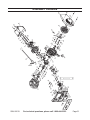
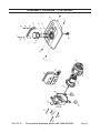
PARTS LIST
Part Description Qty.
1 Left Crankcase 1
2 Right Crankcase 2
3 Bearing (6004) 2
4 Hole Circlip (#42) 1
5 Oil Seal (20 x 30 x 7) 2
6 Pin (10 x 7 x 14) 2
7 Stud (AM6 x 50) 2
8 Flange Nut (M6) 4
9 Flange Bolt (M6 x 45) 4
10 Stud (AM6 x 100) 2
11 Oil Seal (6 x 12 x 7) 1
12 Governor Shaft 1
13 Washer (6 x 10) 2
14 Governor Fork 1
15 Cross Round Head Bolt (M3 x 8) 2
16 Spring Washer (#3) 2
17 Governor Arm 1
18 Collar Bushing 1
19 Weight Comp 1
20 Flange Bolt (M6 x 16) 4
21 Crankshaft Assy. 1
22 Circlip 2
23 Piston Pin 1
24 Roller Bearing (14 x 10 x 14) 1
25 Piston 1
26 Second Piston Ring 1
27 First Piston Ring 1
28 Cylinder Gasket 1
29 Cylinder 1
30 Cylinder Cap Gasket 1
31 Cylinder Cap 1
32 Flange Bolt (M6 x 105) 2
33 Nut (M6 x 18) 2
34 Cylinder Cap Cover 1
35 Flange Bolt (M6 x 12) 10
36 Ignition Coil Assy. 1
37 Clamp 1
38 Spring Washer (#6) 7
39 Cross Round Head Bolt (M6 x 16) 2
40 Flywheel 1
41 Flange Nut (M10 x 1.25) 1
Part Description Qty.
42 Recoil Starter Assy. 1
43 Intake Valve Gasket 1
44 Intake Valve Assy. 1
45 Flange Bolt (M6 x 20) 4
46 Stud (AM6 x 60) 2
47 Intake Gasket 1
48 Carburetor 1
49 Carburetor Gasket (B) 1
50 Carburetor Gasket (A) 1
51 Supporting Plate 1
52 Compression Spring 1
53 Cross Round Head Bolt (M6 x 40) 1
54 Rod Link 1
55 Tension Spring 1
56 Governor Spring 1
57 Control Panel 1
58 Capacitor 1
59 Self Tapping Screw (ST4.2 x 13) 1
60 Alternator Stator 1
61 Alternator Rotor 1
62 Flange Bolt (M8 x 156) 1
63 Rear Cover 1
64 Flange Bolt (M6 x 80) 3
65 Washer (#6) 3
66 Flange Bolt (M6 x 10) 2
67 1
68 1
69 Flange Bolt (M6 x 16) 2
70 CDI Winding 1
71 Spark Plug 1
72 Absorber 4
73 Fuel Tank 1
74 Strainer 1
75 Fuel Cup 1
76 Fuel Tank Cap 1
77 Handle 1
78 Cross Round Head Bolt (M6 x 30) 1
79 Washer (#6) 2
80 Fuel Switch 1
81 Rubber 1
82 Choke Lever 1
Page is loading ...
Page is loading ...
Page is loading ...
Page is loading ...
Page is loading ...
-
 1
1
-
 2
2
-
 3
3
-
 4
4
-
 5
5
-
 6
6
-
 7
7
-
 8
8
-
 9
9
-
 10
10
-
 11
11
-
 12
12
-
 13
13
-
 14
14
-
 15
15
-
 16
16
-
 17
17
-
 18
18
-
 19
19
-
 20
20
-
 21
21
-
 22
22
-
 23
23
-
 24
24
-
 25
25


Chicago Electric 66619 User manual
- Category
- Power generators
- Type
- User manual
Ask a question and I''ll find the answer in the document
Finding information in a document is now easier with AI
Related papers
-
Chicago Electric 96898 Set Up And Operating Instructions Manual
-
-
-
-
-
-
-
-
-
Other documents
-
Togo POWER GG1000 Owner's manual
-
Dirty Hand Tools 101105 Operating instructions
-
Harbor Freight Tools 96500 User manual
-
 Greyhound 66015 Set Up, Operating, And Servicing Instructions
-
-
 Greyhound 97079 Set Up, Operating, And Servicing Instructions
-
-
-
-
CHICAGO 66604 Set Up, Operating, And Servicing Instructions

