Draytek VigorSwitch G1080 Owner's manual
- Category
- Network switches
- Type
- Owner's manual

i

VigorSwitch G1080 User’s Guide
ii
VigorSwitch G1080
Smart Lite Giga Switch
User’s Guide
Version: 1.0
Firmware Version: V1.04.04
Date: June 5, 2018
(For future update, please visit DrayTek web site for further information)

VigorSwitch G1080 User’s Guide
iii
Intellectual Property Rights (IPR) Information
Copyrights
© All rights reserved. This publication contains information that is protected by
copyright. No part may be reproduced, transmitted, transcribed, stored in a
retrieval system, or translated into any language without written permission from
the copyright holders.
Trademarks
The following trademarks are used in this document:
Microsoft is a registered trademark of Microsoft Corp.
Windows, Windows 95, 98, Me, NT, 2000, XP, 7 and Explorer are
trademarks of Microsoft Corp.
Apple and Mac OS are registered trademarks of Apple Inc.
Other products may be trademarks or registered trademarks of their
respective manufacturers.
Caution and Electronic Emission Notices
Caution
Circuit devices are sensitive to static electricity, which can damage their delicate
electronics. Dry weather conditions or walking across a carpeted floor may cause you
to acquire a static electrical charge.
To protect your device, always:
Touch the metal chassis of your computer to ground the static electrical charge
before you pick up the circuit device.
Pick up the device by holding it on the left and right edges only.
Warranty
We warrant to the original end user (purchaser) that the device will be free from any
defects in workmanship or materials for a period of one (1) years from the date of
purchase from the dealer. Please keep your purchase receipt in a safe place as it
serves as proof of date of purchase. During the warranty period, and upon proof of
purchase, should the product have indications of failure due to faulty workmanship
and/or materials, we will, at our discretion, repair or replace the defective products or
components, without charge for either parts or labor, to whatever extent we deem
necessary tore-store the product to proper operating condition. Any replacement will
consist of a new or re-manufactured functionally equivalent product of equal value,
and will be offered solely at our discretion. This warranty will not apply if the
product is modified, misused, tampered with, damaged by an act of God, or subjected
to abnormal working conditions. The warranty does not cover the bundled or licensed
software of other vendors. Defects which do not significantly affect the usability of
the product will not be covered by the warranty. We reserve the right to revise the
manual and online documentation and to make changes from time to time in the
contents hereof without obligation to notify any person of such revision or changes.
Be a Registered
Owner
Web registration is preferred. You can register your Vigor device via
http://www.draytek.com.
Firmware & Tools
Updates
Due to the continuous evolution of DrayTek technology, all devices will be regularly
upgraded. Please consult the DrayTek web site for more information on newest
firmware, tools and documents.
http://www.draytek.com

VigorSwitch G1080 User’s Guide
iv
T
T
a
a
b
b
l
l
e
e
o
o
f
f
C
C
o
o
n
n
t
t
e
e
n
n
t
t
s
s
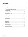
Chapter 1: Introduction.....................................................................................................1
1.1 Overview................................................................................................................................. 1
1.2 Features.................................................................................................................................. 1
1.3 Packing List............................................................................................................................. 2
1.4 LED Indicators and Connectors.............................................................................................. 3
1.5 Hardware Installation .............................................................................................................. 4
1.5.1 Configuring the Management Agent of Switch................................................................. 6
1.5.2 IP Address Assignment .................................................................................................... 7
1.6 Typical Applications................................................................................................................11
Chapter 2: Basic Concept and Management.................................................................13
2.1 What’s the Ethernet............................................................................................................... 13
2.2 Media Access Control (MAC)................................................................................................ 15
2.3 Flow Control.......................................................................................................................... 20
Chapter 3: Operation of Web-based Management........................................................23
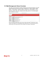
3.1 Web Management Home Overview...................................................................................... 24
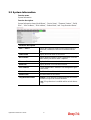
3.2 System Information............................................................................................................... 25
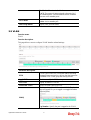
3.3 Port Statistics ........................................................................................................................ 26
3.4 Link Aggregation ................................................................................................................... 26
3.5 VLAN..................................................................................................................................... 27
3.6 Multicast................................................................................................................................ 28
3.7 QoS....................................................................................................................................... 29
3.8 Rate Limiting......................................................................................................................... 31
3.9 Storm Control........................................................................................................................ 32
3.10 Loop Prevention.................................................................................................................. 33
3.11 Port Mirroring....................................................................................................................... 34
3.12 System Maintenance........................................................................................................... 35
Chapter 4: Trouble Shooting...........................................................................................37
4.1 Resolving No Link Condition.................................................................................................37
4.2 Q & A..................................................................................................................................... 37

VigorSwitch G1080 User’s Guide
1
C
C
h
h
a
a
p
p
t
t
e
e
r
r
1
1
:
:
I
I
n
n
t
t
r
r
o
o
d
d
u
u
c
c
t
t
i
i
o
o
n
n
1
1
.
.
1
1
O
O
v
v
e
e
r
r
v
v
i
i
e
e
w
w
VigorSwitch G1080 is a standard switch that meets all IEEE 802.3/u/x/z Gigabit, Fast
Ethernet specifications. The switch has 8 10/100/1000Mbps TP ports. It supports http
interface for switch management. The network administrator can logon the switch to
monitor, configure and control each port’s activity. In addition, the switch implements the
QoS (Quality of Service), VLAN, and Trunking. It is suitable for office application.
10/100/1000Mbps TP is a standard Ethernet port that meets all IEEE 802.3/u/x/z Gigabit,
Fast Ethernet specifications. 1000Mbps SFP Fiber transceiver is a Gigabit Ethernet port
that fully complies with all IEEE 802.3z and 1000Base-SX/LX standards.
Below shows key features of this device:
Q
Q
o
o
S
S
The switch offers powerful QoS function. This function supports 802.1p VLAN tag priority
and DSCP on Layer 3 of network framework.
V
V
L
L
A
A
N
N
Support IEEE802.1Q Tag-based VLAN. Support 8 active VLANs and VLAN ID 1~4094.
P
P
o
o
r
r
t
t
T
T
r
r
u
u
n
n
k
k
i
i
n
n
g
g
Allows one or more links to be aggregated together to form a Link Aggregation Group by
the static setting.
1
1
.
.
2
2
F
F
e
e
a
a
t
t
u
u
r
r
e
e
s
s
The VigorSwitch G1080, a standalone off-the-shelf switch, provides the comprehensive
features listed below for users to perform system network administration and efficiently
and securely serve your network.
H
H
a
a
r
r
d
d
w
w
a
a
r
r
e
e
8 10/100/1000Mbps Auto-negotiation Gigabit Ethernet TP ports
Jumbo frame support 9KB
Programmable classifier for QoS (Layer 2)
8K MAC address and support VLAN ID(1~4094)
Per-port shaping, policing, and Broadcast Storm Control
Full-duplex flow control (IEEE802.3x) and half-duplex backpressure
Extensive front-panel diagnostic LEDs; System: Power, TP Port1-8: LINK/ACT,
10/100/1000Mbps
M
M
a
a
n
n
a
a
g
g
e
e
m
m
e
e
n
n
t
t
Supports per port traffic monitoring counters
Supports a snapshot of the system Information when you login

VigorSwitch G1080 User’s Guide
2
Supports port mirror function
Supports the static trunk function
Supports 802.1Q VLAN
Maximal packet length can be up to 9600 bytes for jumbo frame application
Supports Broadcasting Suppression to avoid network suspended or crashed
Supports to send the trap event while monitored events happened
Supports default configuration which can be restored to overwrite the current
configuration which is working on via Web UI and Reset button of the switch
Built-in web-based management, providing a more convenient UI for the user
1
1
.
.
3
3
P
P
a
a
c
c
k
k
i
i
n
n
g
g
L
L
i
i
s
s
t
t
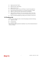
Before you start installing the switch, verify that the package contains the following:
VigorSwitch G1080
AC
Power Cord
Quick Start Guide
Please notify your sales representative immediately if any of the aforementioned items is
missing or damaged.

VigorSwitch G1080 User’s Guide
3
1
1
.
.
4
4
L
L
E
E
D
D
I
I
n
n
d
d
i
i
c
c
a
a
t
t
o
o
r
r
s
s
a
a
n
n
d
d
C
C
o
o
n
n
n
n
e
e
c
c
t
t
o
o
r
r
s
s
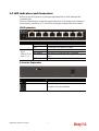
Before you use the Vigor device, please get acquainted with the LED indicators and
connectors first.
There are 8 Ethernet ports on the front panel of the switch. LED display area, locating on
the front panel, contains an ACT, Power LED and 8 ports working status of the switch.
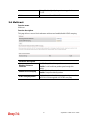
L
L
E
E
D
D
E
E
x
x
p
p
l
l
a
a
n
n
a
a
t
t
i
i
o
o
n
n
LED Color Explanation
On (Green)
The switch is powered on and runs normally.
PWR/SYS
Off
The switch is not ready or is failed.
On (Green)
The device is connected with 1000Mbps.
On (Amber) The device is connected with 10/100Mbps.
Blinking The system is sending or receiving data through the
port.
RJ 45
LNK/ACT for
Ports 1 ~ 8
Off The port is disconnected or the link is failed.
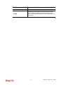
C
C
o
o
n
n
n
n
e
e
c
c
t
t
o
o
r
r
E
E
x
x
p
p
l
l
a
a
n
n
a
a
t
t
i
i
o
o
n
n
Interface Description
Security hole.
Connecter for a power adapter.

VigorSwitch G1080 User’s Guide
4
1
1
.
.
5
5
H
H
a
a
r
r
d
d
w
w
a
a
r
r
e
e
I
I
n
n
s
s
t
t
a
a
l
l
l
l
a
a
t
t
i
i
o
o
n
n
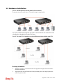
Case 1: All switch ports are in the same local area network.
Every port can access each other. (*The switch image is sample only.)
If VLAN is enabled and configured, each node in the network that can communicate each
other directly is bounded in the same VLAN area.
Case 2: The same VLAN members can be at different switches with the same VID
D
D
e
e
s
s
k
k
t
t
o
o
p
p
I
I
n
n
s
s
t
t
a
a
l
l
l
l
a
a
t
t
i
i
o
o
n
n
1. Install the switch on a level surface that can support the weight of the unit and the
relevant components.
2. Plug the switch with the female end of the provided power cord and plug the male
end to the power outlet.

VigorSwitch G1080 User’s Guide
5
I
I
n
n
s
s
t
t
a
a
l
l
l
l
i
i
n
n
g
g
N
N
e
e
t
t
w
w
o
o
r
r
k
k
C
C
a
a
b
b
l
l
e
e
s
s
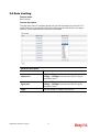
Crossover or straight-through cable: All the ports on the switch support
Auto-MDI/MDI-X functionality. Both straight-through or crossover cables can be used
as the media to connect the switch with PCs as well as other devices like switches, hubs
or router.
Category 3, 4, 5 or 5e, 6 UTP/STP cable: To make a valid connection and obtain the
optimal performance, an appropriate cable that corresponds to different
transmitting/receiving speed is required. To choose a suitable cable, please refer to the
following table.
Media Speed Wiring
10 Mbps Category 3,4,5 UTP/STP
100Mbps Category 5 UTP/STP
10/100/1000
Mbps copper
1000 Mbps Category 5e, 6 UTP/STP

VigorSwitch G1080 User’s Guide
6
1
1
.
.
5
5
.
.
1
1
C
C
o
o
n
n
f
f
i
i
g
g
u
u
r
r
i
i
n
n
g
g
t
t
h
h
e
e
M
M
a
a
n
n
a
a
g
g
e
e
m
m
e
e
n
n
t
t
A
A
g
g
e
e
n
n
t
t
o
o
f
f
S
S
w
w
i
i
t
t
c
c
h
h
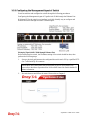
Users can monitor and configure the switch through the following procedures.
Configuring the Management Agent of VigorSwitch G1080 through the Ethernet Port.
Web-based UI for the switch is an interface in a highly friendly way to configure and
monitor the switch through the switch’s Ethernet port.
Managing VigorSwitch G1080 through Ethernet Port
Before start using the switch, the IP address setting of the switch should be done, then
perform the following steps:
1. Set up a physical path between the configured the switch and a PC by a qualified UTP
Cat. 5 cable with RJ-45 connector.
Note: If PC directly connects to the switch, you have to setup the same subnet mask
between them. But, subnet mask may be different for the PC in the remote site.
Please refer to the above figure about the 24-Port GbE Smart Lite Switch default IP
address information.
2. Run web browser and follow the menu. Please refer to Chapter 3.

VigorSwitch G1080 User’s Guide
7
1
1
.
.
5
5
.
.
2
2
I
I
P
P
A
A
d
d
d
d
r
r
e
e
s
s
s
s
A
A
s
s
s
s
i
i
g
g
n
n
m
m
e
e
n
n
t
t
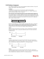
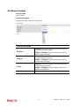
For IP address configuration, there are three parameters needed to be filled in. They are IP
address, Subnet Mask, Default Gateway and DNS.
IP address:
The address of the network device in the network is used for internetworking
communication. Its address structure looks is shown below. It is “classful” because it is
split into predefined address classes or categories.
Each class has its own network range between the network identifier and host identifier in
the 32 bits address. Each IP address comprises two parts: network identifier (address) and
host identifier (address). The former indicates the network where the addressed host resides,
and the latter indicates the individual host in the network which the address of host refers to.
And the host identifier must be unique in the same LAN. Here the term of IP address we
used is version 4, known as IPv4.
Network identifier Host identifier
32 bits
With the classful addressing, it divides IP address into three classes, class A, class B and
class C. The rest of IP addresses are for multicast and broadcast. The bit length of the
network prefix is the same as that of the subnet mask and is denoted as IP address/X, for
example, 192.168.1.0/24. Each class has its address range described below.
Class A:
Address is less than 126.255.255.255. There are a total of 126 networks can be defined
because the address 0.0.0.0 is reserved for default route and 127.0.0.0/8 is reserved for
loopback function.
Class B:
IP address range between 128.0.0.0 and 191.255.255.255. Each class B network has a
16-bit network prefix followed 16-bit host address. There are 16,384 (2^14)/16 networks
able to be defined with a maximum of 65534 (2^16 –2) hosts per network.
Class C:
IP address range between 192.0.0.0 and 223.255.255.255. Each class C network has a
24-bit network prefix followed 8-bit host address. There are 2,097,152 (2^21)/24 networks
able to be defined with a maximum of 254 (2^8 –2) hosts per network.

VigorSwitch G1080 User’s Guide
8
Class D and E:
Class D is a class with first 4 MSB (Most significance bit) set to 1-1-1-0 and is used for IP
Multicast. See also RFC 1112. Class E is a class with first 4 MSB set to 1-1-1-1 and is used
for IP broadcast.
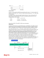
According to IANA (Internet Assigned Numbers Authority), there are three specific IP
address blocks reserved and able to be used for extending internal network. We call it
Private IP address and list below:
Class A 10.0.0.0 --- 10.255.255.255
Class B 172.16.0.0 --- 172.31.255.255
Class C 192.168.0.0 --- 192.168.255.255
Please refer to RFC 1597 and RFC 1466 for more information.
Subnet mask:
It means the sub-division of a class-based network or a CIDR block. The subnet is used to
determine how to split an IP address to the network prefix and the host address in bitwise
basis. It is designed to utilize IP address more efficiently and ease to manage IP network.
For a class B network, 128.1.2.3, it may have a subnet mask 255.255.0.0 in default, in
which the first two bytes is with all 1s. This means more than 60 thousands of nodes in flat
IP address will be at the same network. It’s too large to manage practically. Now if we
divide it into smaller network by extending network prefix from 16 bits to, say 24 bits,
that’s using its third byte to subnet this class B network. Now it has a subnet mask
255.255.255.0, in which each bit of the first three bytes is 1. It’s now clear that the first two
bytes is used to identify the class B network, the third byte is used to identify the subnet
within this class B network and, of course, the last byte is the host number.
Not all IP address is available in the sub-netted network. Two special addresses are
reserved. They are the addresses with all zero’s and all one’s host number. For example, an
IP address 128.1.2.128, what IP address reserved will be looked like? All 0s mean the
network itself, and all 1s mean IP broadcast.

VigorSwitch G1080 User’s Guide
9
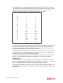
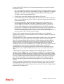
In this diagram, you can see the subnet mask with 25-bit long, 255.255.255.128, contains
126 members in the sub-netted network. Another is that the length of network prefix equals
the number of the bit with 1s in that subnet mask. With this, you can easily count the
number of IP addresses matched. The following table shows the result.
Prefix Length No. of IP matched No. of Addressable IP
/32 1 -
/31 2 -
/30 4 2
/29 8 6
/28 16 14
/27 32 30
/26 64 62
/25 128 126
/24 256 254
/23 512 510
/22 1024 1022
/21 2048 2046
/20 4096 4094
/19 8192 8190
/18 16384 16382
/17 32768 32766
/16 65536 65534
According to the scheme above, a subnet mask 255.255.255.0 will partition a network with
the class C. It means there will have a maximum of 254 effective nodes existed in this
sub-netted network and is considered a physical network in an autonomous network. So it
owns a network IP address which may looks like 168.1.2.0.
With the subnet mask, a bigger network can be cut into small pieces of network. If we want
to have more than two independent networks in a worknet, a partition to the network must
be performed. In this case, subnet mask must be applied.
For different network applications, the subnet mask may look like 255.255.255.240. This
means it is a small network accommodating a maximum of 15 nodes in the network.
Default gateway:
For the routed packet, if the destination is not in the routing table, all the traffic is put into
the device with the designated IP address, known as default router. Basically, it is a routing
policy. The gateway setting is used for Trap Events Host only in the switch.
For assigning an IP address to the switch, you just have to check what the IP address of the
network will be connected with the switch. Use the same network address and append your
host address to it.

VigorSwitch G1080 User’s Guide
10
First, IP Address: as shown above, enter “192.168.1.224”, for instance. For sure, an IP
address such as 192.168.1.x must be set on your PC.
Second, Subnet Mask: as shown above, enter “255.255.255.0”. Any subnet mask such as
255.255.255.x is allowable in this case.
Note
: The DHCP Setting is enabled in default.

VigorSwitch G1080 User’s Guide
11
1
1
.
.
6
6
T
T
y
y
p
p
i
i
c
c
a
a
l
l
A
A
p
p
p
p
l
l
i
i
c
c
a
a
t
t
i
i
o
o
n
n
s
s
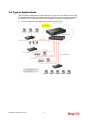
The VigorSwitch implements 8 Gigabit Ethernet TP ports with auto MDIX and two slots
for the removable module supporting comprehensive fiber types of connection including
LC and BiDi-LC SFP modules. The switch is suitable for the following applications.
Central Site/Remote site application is used in carrier or ISP

VigorSwitch G1080 User’s Guide
12
It is a system wide basic reference connection diagram. This diagram demonstrates how the
switch connects with other network devices and hosts.
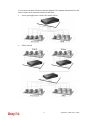
Peer-to-peer application is used in two remote offices
Office network

VigorSwitch G1080 User’s Guide
13
C
C
h
h
a
a
p
p
t
t
e
e
r
r
2
2
:
:
B
B
a
a
s
s
i
i
c
c
C
C
o
o
n
n
c
c
e
e
p
p
t
t
a
a
n
n
d
d
M
M
a
a
n
n
a
a
g
g
e
e
m
m
e
e
n
n
t
t
This chapter will tell you the basic concept of features to manage this switch and how they
work.
2
2
.
.
1
1
W
W
h
h
a
a
t
t
’
’
s
s
t
t
h
h
e
e
E
E
t
t
h
h
e
e
r
r
n
n
e
e
t
t
Ethernet originated and was implemented at Xerox in Palo Alto, CA in 1973 and was
successfully commercialized by Digital Equipment Corporation (DEC), Intel and Xerox
(DIX) in 1980. In 1992, Grand Junction Networks unveiled a new high speed Ethernet with
the same characteristic of the original Ethernet but operated at 100Mbps, called Fast
Ethernet now. This means Fast Ethernet inherits the same frame format, CSMA/CD,
software interface. In 1998, Gigabit Ethernet was rolled out and provided 1000Mbps. Now
10G/s Ethernet is under approving. Although these Ethernet have different speed, they still
use the same basic functions. So they are compatible in software and can connect each
other almost without limitation. The transmission media may be the only problem.
In the above figure, we can see that Ethernet locates at the Data Link layer and Physical
layer and comprises three portions, including logical link control (LLC), media access
control (MAC), and physical layer. The first two comprises Data link layer, which
performs splitting data into frame for transmitting, receiving acknowledge frame, error
checking and re-transmitting when not received correctly as well as provides an error-free
channel upward to network layer.

VigorSwitch G1080 User’s Guide
14
This above diagram shows the Ethernet architecture, LLC sub-layer and MAC sub-layer,
which are responded to the Data Link layer, and transceivers, which are responded to the
Physical layer in OSI model. In this section, we are mainly describing the MAC sub-layer.
L
L
o
o
g
g
i
i
c
c
a
a
l
l
L
L
i
i
n
n
k
k
C
C
o
o
n
n
t
t
r
r
o
o
l
l
(
(
L
L
L
L
C
C
)
)
Data link layer is composed of both the sub-layers of MAC and MAC-client. Here MAC
client may be logical link control or bridge relay entity.
Logical link control supports the interface between the Ethernet MAC and upper layers in
the protocol stack, usually Network layer, which is nothing to do with the nature of the
LAN. So it can operate over other different LAN technology such as Token Ring, FDDI
and so on. Likewise, for the interface to the MAC layer, LLC defines the services with the
interface independent of the medium access technology and with some of the nature of the
medium itself.
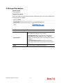
The table above is the format of LLC PDU. It comprises four fields, DSAP, SSAP, Control
and Information. The DSAP address field identifies the one or more service access points,
in which the I/G bit indicates it is individual or group address. If all bit of DSAP is 1s, it’s a
global address. The SSAP address field identifies the specific services indicated by C/R bit

VigorSwitch G1080 User’s Guide
15
(command or response). The DSAP and SSAP pair with some reserved values indicates
some well-known services listed in the table below.
LLC type 1 connectionless service, LLC type 2 connection-oriented service and LLC type
3 acknowledge connectionless service are three types of LLC frame for all classes of
service. In Fig 3-2, it shows the format of Service Access Point (SAP). Please refer to
IEEE802.2 for more details.
2
2
.
.
2
2
M
M
e
e
d
d
i
i
a
a
A
A
c
c
c
c
e
e
s
s
s
s
C
C
o
o
n
n
t
t
r
r
o
o
l
l
(
(
M
M
A
A
C
C
)
)
M
M
A
A
C
C
A
A
d
d
d
d
r
r
e
e
s
s
s
s
i
i
n
n
g
g
Because LAN is composed of many nodes, for the data exchanged among these nodes,
each node must have its own unique address to identify who should send the data or should
receive the data. In OSI model, each layer provides its own mean to identify the unique
address in some form, for example, IP address in network layer.

VigorSwitch G1080 User’s Guide
16
The MAC is belonged to Data Link Layer (Layer 2), the address is defined to be a 48-bit
long and locally unique address. Since this type of address is applied only to the Ethernet
LAN media access control (MAC), they are referred to as MAC addresses.
The first three bytes are Organizational Unique Identifier (OUI) code assigned by IEEE.
The last three bytes are the serial number assigned by the vendor of the network device. All
these six bytes are stored in a non-volatile memory in the device. Their format is as the
following table and normally written in the form as aa-bb-cc-dd-ee-ff, a 12 hexadecimal
digits separated by hyphens, in which the aa-bb-cc is the OUI code and the dd-ee-ff is the
serial number assigned by manufacturer.
Bit 47 Bit 0
1
st
byte 2
nd
byte 3
rd
byte 4
th
byte 5
th
byte 6
th
byte
OUI code Serial number
The first bit of the first byte in the Destination address (DA) determines the address to be a
Unicast (0) or Multicast frame (1), known as I/G bit indicating individual (0) or group (1).
So the 48-bit address space is divided into two portions, Unicast and Multicast. The second
bit is for global-unique (0) or locally-unique address. The former is assigned by the device
manufacturer, and the later is usually assigned by the administrator. In practice,
global-unique addresses are always applied.
A unicast address is identified with a single network interface. With this nature of MAC
address, a frame transmitted can exactly be received by the target an interface the
destination MAC points to.
A multicast address is identified with a group of network devices or network interfaces. In
Ethernet, a many-to-many connectivity in the LANs is provided. It provides a mean to send
a frame to many network devices at a time. When all bit of DA is 1s, it is a broadcast,
which means all network device except the sender itself can receive the frame and
response.
E
E
t
t
h
h
e
e
r
r
n
n
e
e
t
t
F
F
r
r
a
a
m
m
e
e
F
F
o
o
r
r
m
m
a
a
t
t
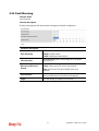
There are two major forms of Ethernet frame, type encapsulation and length encapsulation,
both of which are categorized as four frame formats 802.3/802.2 SNAP, 802.3/802.2,
Ethernet II and Netware 802.3 RAW. We will introduce the basic Ethernet frame format
defined by the IEEE 802.3 standard required for all MAC implementations. It contains
seven fields explained below.
PRE SFD DA SA Type/Length Data Pad bit if any FCS
7 7 6 6 2 46-1500 4
Preamble (PRE) - The PRE is 7-byte long with alternating pattern of ones and zeros used
to tell the receiving node that a frame is coming, and to synchronize the physical receiver
with the incoming bit stream. The preamble pattern is:
10101010 10101010 10101010 10101010 10101010 10101010 10101010
Start-of-frame delimiter (SFD) - The SFD is one-byte long with alternating pattern of
ones and zeros, ending with two consecutive 1-bits. It immediately follows the preamble
and uses the last two consecutive 1s bit to indicate that the next bit is the start of the data
packet and the left-most bit in the left-most byte of the destination address. The SFD
pattern is 10101011.
Destination address (DA) - The DA field is used to identify which network device(s)
should receive the packet. It is a unique address. Please see the section of MAC addressing.
Page is loading ...
Page is loading ...
Page is loading ...
Page is loading ...
Page is loading ...
Page is loading ...
Page is loading ...
Page is loading ...
Page is loading ...
Page is loading ...
Page is loading ...
Page is loading ...
Page is loading ...
Page is loading ...
Page is loading ...
Page is loading ...
Page is loading ...
Page is loading ...
Page is loading ...
Page is loading ...
Page is loading ...
-
 1
1
-
 2
2
-
 3
3
-
 4
4
-
 5
5
-
 6
6
-
 7
7
-
 8
8
-
 9
9
-
 10
10
-
 11
11
-
 12
12
-
 13
13
-
 14
14
-
 15
15
-
 16
16
-
 17
17
-
 18
18
-
 19
19
-
 20
20
-
 21
21
-
 22
22
-
 23
23
-
 24
24
-
 25
25
-
 26
26
-
 27
27
-
 28
28
-
 29
29
-
 30
30
-
 31
31
-
 32
32
-
 33
33
-
 34
34
-
 35
35
-
 36
36
-
 37
37
-
 38
38
-
 39
39
-
 40
40
-
 41
41


Draytek VigorSwitch G1080 Owner's manual
- Category
- Network switches
- Type
- Owner's manual
Ask a question and I''ll find the answer in the document
Finding information in a document is now easier with AI
Related papers
-
Draytek VigorSwitch G2280x Owner's manual
-
-
Draytek VigorSwitch G2540x Owner's manual
-
-
-
-
-
-
-
Other documents
-
Ruby Tech GS-1208M User manual
-
Abocom Switch UFE2000 User manual
-
Sapido GS810w Quick setup guide
-
-
-
-
H3C S3100-52P Operating instructions
-
LevelOne GEP-0950 User manual
-
-