
Copyright 2008 DB Industries, Inc.
USER INSTRUCTION MANUAL
EVOLUTION™ PORTABLE PYLON ANCHOR
This manual should be used as part of an employee training program as
required by OSHA.
User Instruction Manual for:
Evolution™ Portable Pylon Anchor
(Model Number: 7256000)
WARNING: This product is part of an Emergency Escape System or Climb
Assist System. The user must follow the manufacturer’s instructions for each
component of the system. These instructions must be provided to the user of
this equipment (user/rescuer). The user/rescuer must read and understand
these instructions before using this equipment. Manufacturer’s instructions
must be followed for proper use and maintenance of this equipment. Alterations
or misuse of this equipment, or failure to follow these instructions, may result
in serious injury or death.
IMPORTANT: If you have questions on the use, care, or suitability of this
equipment for your application contact Capital Safety.
IMPORTANT: Record the product identication information from the ID label in
the Inspection and Maintenance Log in Section 9 of this manual.
DESCRIPTION
7256000 - EVOLUTION™ PORTABLE PYLON ANCHOR:
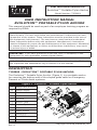
The Evolution™ Portable Pylon Anchor (Figure 1) is a portable anchor
for securing the bottom end of the sloped guide cable on Emergency
Descent or Climb Assist systems.
Figure 1 - Evolution™ Portable Pylon Anchor
A Weight Box Anchor
B Weight Plates
C Receiver Fork
D RH Fork
E LH Fork
F Anchor Tube
G Anchor Eyelet
H Stake
I Stake Socket
J Lifting Eye
K Fork Lift Pockets
L Tension Indicators
B
D
G
E
F
C
L
H
I
A
J
K
K
Form No. 5902410
Rev. A


1
The Pylon Anchor is comprised of a Weight Box Anchor assembly (1A)
with twenty 45 lb (20.4 kg) Evolution™ Weight Plates (1B). A Receiver
Fork assembly (1C) with Right Hand and Left Hand Fork assemblies (1D
and 1E) attaches to the front of the Weight Box Anchor to prevent the
Pylon Anchor from sliding forward from the pull of the attached Guide
Cable. An Anchor Tube (1F) with Anchor Eyelet (1G) mounts on the
Receiver Fork assembly and serves as the attachment point for the Guide
Cable. Two Stakes (1H) pass through Stake Sockets (1I) on the back
of the Weight Box Anchor and are pounded into the ground to secure
the back end of the Pylon Anchor. Four Stake Sockets are available
on the Weight Box Anchor to allow repositioning of the Stakes to clear
obstructions. A Lifting Eye (1J) and Fork Lift Pockets (1K) on the Weight
Box Anchor facilitates transport with the appropriate lifting equipment.
A Tension Indicator (1L) is included with the Pylon Anchor and is
attached between the Anchor Eyelet and Guide Cable to monitor tension
of the cable.
1.0 APPLICATIONS
1.1 PURPOSE: The DBI-SALA Evolution™ Portable Pylon Anchor is
designed for use as the bottom end anchor for the Sloped Guide
Cable on a Emergency Escape System or Guy Cable on a Climb
Assist System (see Figure 2):
A. EMERGENCY RESCUE SYSTEM: The Pylon Anchor is used
with a RollGliss
®
Emergency Descent Device as part of an
Emergency Rescue System for controlled descent from an
elevated structure. The Pylon Anchor is used to secure the
bottom end of the Guide Cable required on sloped descent
systems.
B. CLIMB ASSIST SYSTEM: The Pylon Anchor is used with a
Climb Assist System for applications where worker mobility
and fall protection are needed. The Pylon Anchor is used to
secure the bottom end of the Guy Cable.
WARNING: Do not alter or intentionally misuse this
equipment. Consult Capital Safety before using this
equipment in combination with components or subsystems
other than described in this manual.
C. ADDITIONAL WEIGHT: For situations where work site soil or
other conditions necessitate additional weight, the expandable
design of the Pylon Anchor allows attachment of additional
Weight Box Anchors (see Figure 2).
IMPORTANT: Use of the Pylon Anchor in applications other than the
Emergency Rescue and Climb Assist systems described in this section
requires review and approval by Capital Safety Group Engineering.

2
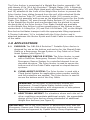
Figure 2 - Pylon Anchor Applications
Emergency Rescue System Climb Assist System
B
A
C
D
E
F
G
H
I
J
K
L
A Emergency Descent Device
B Guide Cable Suspension Bar
C Guide Cable Sleeve
D Guide Cable
E Tension Indicator
F Portable Pylon Anchor
G Safety Block
H Sheave
I Guy Cable
J Counterweight
K Tension Indicator
L Portable Pylon Anchor
Where soil or other conditions necessitate additional weight, the expandable
design allows attachment of additional Weight Box Anchor(s):

3
1.2 LIMITATIONS: The following application limitations must be
recognized and considered before using this product:
A. CAPACITY: The Evolution™ Portable Pylon Anchor is designed
for use by persons with a combined weight (clothing, tools,
etc.) of no more than 310 lbs (141 kg). No more than one
Emergency Descent System or Climb Assist System may be
connected at a time.
B. FREQUENCY OF USE: For Emergency Descent Systems,
only one user may use the system to evacuate the work
area. Multiple, subsequent evacuations are not permitted
without inspection and proper adjustment of the Pylon Anchor
location and Guide Cable tension prior to each evacuation. See
Section 5 for inspection instructions.
C. FREE FALL: Emergency Rescue Systems must be rigged so
that no vertical free fall is possible. See the personal fall arrest
system manufacturer’s instructions for more information.
C. DESCENT SPEED: The speed at which the user descends
when using an Emergency Descent Device increases with the
combined weight of the user. The descent speed will decrease
as the slope of the guide cable decreases. Refer to the User
Instruction Manual included with your DBI-SALA RollGliss
®
Rescue Emergency Descent Device for Guide Cable slope and
distance requirements.
D. ENVIRONMENTAL HAZARDS: Use of this equipment in
areas with environmental hazards may require additional
precautions to prevent injury to the user or damage to the
equipment. Hazards may include, but are not limited to: heat,
chemicals, corrosive environments, high voltage power lines,
gases, moving machinery, and sharp edges. Contact DBI-SALA
if you have questions about using this equipment where
environmental hazards exist.
E. TRAINING: This equipment must be installed and used by persons
trained in its correct application and use. See Section 4.

4
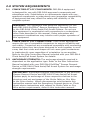
2.0 SYSTEM REQUIREMENTS
2.1 COMPATIBILITY OF COMPONENTS: DBI-SALA equipment
is designed for use with DBI-SALA approved components and
subsystems only. Substitutions or replacements made with non-
approved components or subsystems may jeopardize compatibility
of equipment and may effect the safety and reliability of the
complete system.
WARNING: This equipment was designed specically for use
with DBI-SALA RollGliss
®
Rescue Emergency Descent Devices
or the DBI-SALA Climb Assist/Fall Arrest System. Do not use
this equipment in combination with components or subsystems
other than described in this manual. Some subsystem and
component combinations may interfere with proper operation of
this equipment.
2.2 COMPATIBILITY OF CONNECTORS: Climb Assist applications
require the use of compatible connectors to ensure reliability and
user safety. Connectors are considered compatible with connecting
elements when they have been designed to work together in such
a way that their sizes and shapes do not cause gate mechanisms
to inadvertently open regardless of orientation to one another.
Refer to the User Instruction Manual included with your DBI-SALA
Climb Assist/Fall Arrest System for details.
2.3 ANCHORAGE STRENGTH: The anchorage strength required is
dependent on the application type. Refer to the User Instruction
Manual included with your DBI-SALA RollGliss
®
Rescue Descent
Device or DBI-SALA Climb Assist/Fall Arrest System for anchorage
strength requirements.
IMPORTANT: Anchorage strength requirements in the RollGliss
®
Rescue Descent Device and DBI-SALA Climb Assist/Fall Arrest
System apply to anchorage of those respective devices to the
structure and not anchorage of the Guide Cable or Guy Wire
to the Pylon Anchor. Where discrepancies exist between this
instruction manual and the Emergency Descent device or Climb
Assist device instructions with respect to Guide Cable or Guy
Wire anchor requirements, defer to this instruction manual.

5
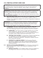
3.0 INSTALLATION AND USE
WARNING: Do not alter or intentionally misuse this equipment.
Use caution when using this equipment around moving machinery,
electrical hazards, chemical hazards, sharp edges, and abrasive
surfaces.
WARNING: Consult your doctor if there is any reason to doubt your
tness to safely absorb the shock from a fall arrest or suspension.
Age and tness seriously affect a worker’s ability to withstand falls.
Pregnant women or minors must not use DBI-SALA equipment unless
in an emergency situation.
3.1 BEFORE EACH USE: Before each use of this equipment, carefully
inspect it to assure that it is in serviceable condition. Refer to
Section 5 for inspection details. Do not use if inspection reveals an
unsafe condition.
WARNING: For Emergency Descent Systems, multiple, subsequent
evacuations are not permitted without inspection and adjustment
of the Pylon Anchor location and Guide Cable tension prior to each
evacuation. See Section 5 for inspection instructions.
3.2 PLANNING: Plan your system before installation. Take into
consideration all factors that affect safety when the system is in
use. The following list gives some important points to consider:
A. SURFACES: The Pylon Anchor is approved for use on sand,
mud, packed soil, soft soil, and frozen soil. (The anchor
must properly engage the soil.) It is not intended for use on
concrete, wood, metal, bituminous pavement, or ice.
B. TESTING THE SYSTEM: For Emergency Descent applications,
all installations should be veried by performing a test
descent. Consult your RollGliss
®
Emergency Descent Device
User Instruction Manual.
C. DESCENT & LANDING AREAS: For Emergency Descent
applications, adequate clear space must be provided around the
descent and landing areas to prevent collision with obstructions
during evacuation.
3.3 INSTALLATION REQUIREMENTS: The following requirements
must be observed to insure safe effective installation of the
Pylon Anchor:
A. WEIGHT PLATES: All 20 Weight Plates must be installed on
the Weight Box Anchor for all Pylon Anchor installations.

6
B. GUIDE CABLES: Guide Cables used with the Pylon Anchor
must be between 3/8 in. (0.95 cm) and 5/8 in. (1.6 cm) in
diameter, must meet the requirements for all systems and
subsystems used, and must not exceed 200 ft. (60 m) in
length.
C. GUIDE CABLE ANGLE: Guide Cable angle must be between
15 degrees and 45 degrees measured from the horizontal.
D. GUIDE CABLE TENSION: The Guide Cable must be properly
tensioned to minimize sag in the cable and ensure the user
reaches the landing area after descent. A Tension Indicator is
included with the Pylon Anchor to verify proper tension on the
Guide Cable (see Section 5.2).
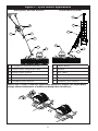
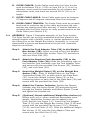
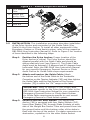
3.4 ASSEMBLY: Figure 3 illustrates assembly of the Pylon Anchor.
The Pylon Anchor can be fully assembled and then placed in the
desired location with a forklift, crane, or similar equipment using
the Lifting Eye on the Weight Box Anchor Assembly, or it can be
transported in pieces and assembled at the job site. Assembly
steps are as follows:
Step 1. Attach the Fork Adaptor Tube (3A) to the Weight
Box Anchor (3B): Insert one end of the Fork Adaptor
Tube into the Weight Box Anchor Tube (3C) and secure
with two Hitch Pins (3D).
Step 2. Attach the Receiver Fork Assembly (3E) to the
Fork Adaptor Tube (3A): Slide the connecting tube on
the Receiver Fork Assembly over the Fork Adaptor Tube
and secure with the provided Cap Screws (3F), Washers
(3G), and Lock Nuts (3H).
Step 3. Mount the Weight Plates (3I) on the Weight Box
Anchor (3B): Slide 10 Weight Plates on the Plate
Containment Rods (3J) on each side of the Plate Rack
(3K). Insert the Weight Locking Tubes (3L) in the
connecting tubes on each side of the Plate Rack (3K) and
secure with the provided Hex Nuts (3M).
Step 4. Attach the Tension Indicator: Position the Tension
Indicator over the Anchor Eyelet (3Q) and pass the bolt
through the Tension Indicator and Anchor Eyelet. Thread
and tighten the included nut.
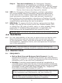
Step 5. (Optional) Attach additional Weight Box Anchor(s):
Where work soil or other conditions necessitate more
weight, Weight Box Anchors can be added to the
Pylon Anchor (see Figure 3.1): Insert the Fork Adaptor
Tube (3.1A) into the Weight Box Anchor Tube (3.1B) and
secure with the provided Cap Screws (3.1C), Washers
(3.1D), and Lock Nuts (3.1E). Slide the additional Weight
Box Anchor (3.1F) onto the Fork Adaptor Tube and
secure with two Hitch Pins (3.1G).

7
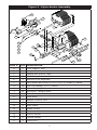
Figure 3 - Pylon Anchor Assembly
A
B
C
D
E
H
G
G
F
I
J
K
L
M
N
O
P
Q
R
S
ITEM # QTY DESCRIPTION
A 1 Fork Adaptor Tube
B 1 Weight Box Anchor
C 1 Weight Box Anchor Tube
D 2 Hitch Pin, 1/2 in x 2-1/2 in
E 1 Receiver Fork Assembly
F 2 Hex Head Cap Screw, 1/2 in x 3-1/2 in, Grade 5, Plated
G 10 SAE Flat Washer, 1/2 in, Plated
H 5 Nylock Nut, 1/2 in
I 20 Evolution™ Weight Plate
J 4 Plate Containment Rods
K 1 Plate Rack
L 2 Weight Locking Tube
M 2 Hex Nut, 1 in
N 2 Rear Stake
O 4 Stake Socket
P 1 Tension Indicator
Q 1 Anchor Eyelet
R 2 Forklift Pocket
S 1 Lifting Eye

8
Figure 3.1 - Adding Weight Box Anchors
A Fork Adaptor
Tube
B Weight Box
Anchor Tube
C Cap Screw
D Washer
E Lock Nut
B
A
C
D
D
E
G
F
3.5 INSTALLATION: This installation procedure describes installation
of the Pylon Anchor and connection of the Guide Cable (Guy
Cable) to the Pylon Anchor. To install all other equipment in the
Emergency Rescue or Climb Assist system, refer to the respective
DBI-DALA User Instruction Manual(s). Refer to Figure 3 for location
of items identied in the following steps:
Step 1. Position the Pylon Anchor: Proper location of the
Pylon Anchor is critical. The Pylon Anchor should be
situated parallel with the Guide Cable and should be
sitting relatively level (see Figure 4). The Guide Cable
Angle must be between 15 degrees and 45 degrees from
horizontal. Refer the DBI-SALA User Instruction Manual
for your specic Emergency Descent Device or Climb
Assist Device for Guide Cable slope requirements.
Step 2. Attach and tension the Guide Cable: Attach
the bottom end of the Guide Cable to the Turnbuckle
Connection on the Tension Indicator (3Q) and then tighten
the Guide Cable until the Red Pointer on the Tension
Indicator (3Q) is within the “OK” range on the label.
IMPORTANT: Refer to Section 3.3 for Guide Cable
requirements specic to the Pylon Anchor. Refer to the
DBI-SALA User Instruction Manual for your respective
Emergency Descent Device or Climb Assist System
for Guide Cable requirements specic to your overall
Emergency Rescue or Climb Assist system.
Step 3. Pound in the two Rear Stakes: The Weight Box
Anchor (3B) is equipped with four Stake Sockets (3O).
Insert Rear Stakes (3N) through Stake Sockets on each
side of the Weight Box Anchor Tube and pound them into
the ground below until the bottom collar of the stake is
ush with the top of the socket. If a stake encounters an
obstruction, reposition it in the other Stake Socket.

9
Step 4. Test the installation: For Emergency Descent
applications, all installations should be veried by
performing a test descent using a 120 lb. (55 kg) weight
(minimum). Consult your RollGliss
®
Emergency Descent
Device User Instruction Manual for details.
3.6 USE: For Emergency Descent Systems, multiple evacuations
are not permitted without inspection and proper adjustment
of the Pylon Anchor location and Guide Cable tension prior to
each successive evacuation. After each descent, inspect the
Pylon Anchor per the inspection instructions in Sections 5.2 and
5.3. Reposition the Pylon Anchor and tension the Guide Cable as
needed before performing the next evacuation.
3.7 REMOVAL: To remove the Pylon Anchor, remove the two Rear
Stakes (3N) and lift the entire unit by the Forklift Pockets (3R)
or Lifting Eye (3S) with a forklift, crane, or other suitable lifting
equipment. If suitable lifting equipment is unavailable, the
Pylon Anchor can be disassembled and moved by hand.
IMPORTANT: Do not lift the Pylon Anchor by the Anchor Eyelet.
4.0 TRAINING
4.1 It is the responsibility of the user to assure they are familiar with
these instructions and are trained in the correct care and use
of this equipment. Users must also be aware of the operating
characteristics, application limits, and consequences of improper
use of this equipment.
IMPORTANT: Training must be conducted without exposing the
trainee to a fall hazard. Training should be repeated on a periodic basis
5.0 INSPECTION
5.1 FREQUENCY:
Before Each Use and Between Each Descent: • Visually
inspect the Evolution™ Portable Pylon Anchor per steps listed in
Sections 5.2 and 5.3. Correct any deciencies discovered during
inspection prior to the next use (evacuation).
Monthly:• A monthly formal inspection should be completed by a
competent person other than the user. A formal inspection should also
be completed if system parameters change (system moved, re-rigged,
anchorages moved, guide cable angle changed, etc.). Inspect the
Pylon Anchor according to Sections 5.2 and 5.3.
NOTE: Record the monthly/formal inspection date and results
in the Inspection and Maintenance Log (see Section 9).
IMPORTANT: Extreme working conditions (harsh environment, prolonged
use, etc.) may require increasing the frequency of inspections.

10
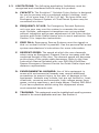
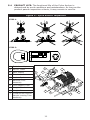
5.2 INSPECTION STEPS: See Figure 4 for item referenced in the
following steps:
Between Each Use:
Step 1. Inspect the position of the Pylon Anchor: Verify that
the anchor has not slid forward allowing excess sag in
the Guide Cable. The Pylon Anchor should be situated
parallel with the Guide Cable and should be sitting
relatively level. The Forks (4A), Weight Box Anchor Teeth
(4B), and Rear Stakes (4C) should all be embedded
securely in the ground.
Step 2. Inspect the Tension Indicator: The Red Pointer on the
Tension Indicator (4D) should be within the “OK” range
on the label when the cable is within the required tension
range.
Step 3. Inspect critical connectors and fasteners: The
Anchor Eyelet (4E) should be securely attached to the
Anchor Tube and the connecting bolt and nut securing
the Tension Indicator (4D) on the Anchor Eyelet should
be tight. The hitch pins, cap screws, and nuts holding the
Receiver Fork Assembly (4F), Fork Adaptor Tube (4G),
and Weight Box Anchor together should all be tight.
Step 4. Inspect the Weight Plates: All twenty Weight Plates
(4I) must be present and effectively secured on the
Weight Rack by the Containment Rods and Weight
Locking Tube Assembly (4J).
Monthly/Formal Inspection:
Include the following steps during monthly/formal inspection:
Step 5. Inspect all components for damage: Make sure
components are not bent and are free of any cracks or
deformities
Step 6. Inspect Forks and Stakes: Inspect the Fork
Assemblies (4A) and Rear Stakes (4C) for any bends,
cracks, corrosion, or deformities that might compromise
their ability to dig into and grip the ground below.
Step 7. Inspect all Connectors and Fasteners: Inspect all
Eyelets, Hitch Pins, Bolts, Nuts, and Washers for cracks,
deformities, or corrosion. Make sure all hardware is
present and secure.
Step 8. Inspect all Labels: All labels must be present and
fully legible (see Section 8). Replace labels if missing or
illegible.
5.3 DEFECTS: If inspection reveals an unsafe or defective condition,
remove the Pylon Anchor from service and contact an authorized
service center.

11
5.4 PRODUCT LIFE: The functional life of the Pylon Anchor is
determined by work conditions and maintenance. As long as the
product passes inspection criteria, it may remain in service.
Figure 4 - Pylon Anchor Inspection
STEP 1.
STEP 2.
A Fork Assembly
B Anchor Teeth
C Rear Stakes
D Tension Indicator
E Anchor Eyelet
F Receiver Fork
Assembly
G Fork Adaptor Tube
H Weight Box Anchor
I Weight Plates
J Containment Rods &
Weight Locking Tube
Assembly
A
A
E
F
G
D
J
H
C
I
B
C

12
6.0 MAINTENANCE, SERVICE, STORAGE
6.1 MAINTENANCE: The Pylon Anchor requires no scheduled
maintenance other than repair or replacement of items found
defective during inspections (see Section 5).
6.2 SERVICE: If components become heavily soiled with grease,
paint, or other substances; clean with appropriate cleaning
solutions. Do not use caustic chemicals that could damage system
components. Clean or replace missing or illegible labels. (See
Section 8 for label examples.)
6.3 STORAGE: Store the Pylon Anchor in a clean dry environment.
Avoid areas where chemical vapors may exist. Thoroughly inspect
the Pylon Anchor after extended storage.
7.0 SPECIFICATIONS
7.1 MATERIALS:
Frame: Powder Coated Steel
D-Ring: Zinc Plated Steel
7.2 WEIGHT:
Assembled Unit
(- Weight Plates): 272 lbs (123.4 kg)
Assembled Unit
(+ Weight Plates): 1,191 lbs (540.2 kg)
Weight Box Anchor
Assembly: 187 lbs (84.8 kg)
Receiver Fork Assembly 77 lbs (34.9 kg)
Rear Stakes 2 @ 7 lbs (3.2 kg) = 14 lbs (6.4 kg)
Weight Plates 20 @ 45 lbs (20.4 kg) = 900 lbs (408.2 kg)
7.3 SIZE:
LENGTH: 64 in (162.6 cm)
WIDTH: 36 in (91.4 cm)
HEIGHT: 28 in (71.1 cm)
7.4 CAPACITY: 1 User, 310 lbs (141 kg), 1 Time/Inspection

13
8.0 LABELING
The following labels should be securely attached to the Pylon Anchor
Warning & Instruction Label
IdenticationLabel

14
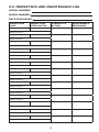
9.0 INSPECTION AND MAINTENANCE LOG
SERIAL NUMBER:
MODEL NUMBER:
DATE PURCHASED:
INSPECTION
DATE
INSPECTION
ITEMS NOTED
CORRECTIVE
ACTION
MAINTENANCE
PERFORMED
Approved By:
Approved By:
Approved By:
Approved By:
Approved By:
Approved By:
Approved By:
Approved By:
Approved By:
Approved By:
Approved By:
Approved By:
Approved By:
Approved By:

15
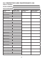
9.0 INSPECTION AND MAINTENANCE LOG
SERIAL NUMBER:
MODEL NUMBER:
DATE PURCHASED:
INSPECTION
DATE
INSPECTION
ITEMS NOTED
CORRECTIVE
ACTION
MAINTENANCE
PERFORMED
Approved By:
Approved By:
Approved By:
Approved By:
Approved By:
Approved By:
Approved By:
Approved By:
Approved By:
Approved By:
Approved By:
Approved By:
Approved By:
Approved By:

16
9.0 INSPECTION AND MAINTENANCE LOG
SERIAL NUMBER:
MODEL NUMBER:
DATE PURCHASED:
INSPECTION
DATE
INSPECTION
ITEMS NOTED
CORRECTIVE
ACTION
MAINTENANCE
PERFORMED
Approved By:
Approved By:
Approved By:
Approved By:
Approved By:
Approved By:
Approved By:
Approved By:
Approved By:
Approved By:
Approved By:
Approved By:
Approved By:
Approved By:


WARRANTY
Equipment offered by DBI-SALA is warranted against factory defects
in workmanship and materials for a period of two years from date of
installation or use by the owner, provided that this period shall not ex-
ceed two years from date of shipment. Upon notice in writing, DBI-SALA
will promptly repair or replace all defective items. DBI-SALA reserves
the right to elect to have any defective item returned to its plant for
inspection before making a repair or replacement. This warranty does
not cover equipment damages resulting from abuse, damage in transit,
or other damage beyond the control of DBI-SALA. This warranty ap-
plies only to the original purchaser and is the only one applicable to our
products, and is in lieu of all other warranties, expressed or implied.
CSG USA
3833 Sala Way
Red Wing, MN 55066-5005
Toll Free: 800.328.6146
Phone: 651.388.8282
Fax: 651.388.5065
solutions@capitalsafety.com
CSG Canada Ltd.
260 Export Boulevard
Mississauga, Ontario L5S 1Y9
Toll Free: 800.387.7484
Phone: 905.795.9333
Fax: 905.795.8777
sales.ca@capitalsafety.com
www.capitalsafety.com
I S O
9 0 0 1
Certicate No. FM 39709
-
 1
1
-
 2
2
-
 3
3
-
 4
4
-
 5
5
-
 6
6
-
 7
7
-
 8
8
-
 9
9
-
 10
10
-
 11
11
-
 12
12
-
 13
13
-
 14
14
-
 15
15
-
 16
16
-
 17
17
-
 18
18
-
 19
19
-
 20
20


DBI-SALA DBI-SALA®Portable Pylon Anchor 7256000, Blue and Silver, 1 EA Operating instructions
- Type
- Operating instructions
- This manual is also suitable for
Ask a question and I''ll find the answer in the document
Finding information in a document is now easier with AI
Related papers
-
3M 3302981 User manual
-
3M DBI-SALA® Rollgliss™ Descender, Sloped/Automatic Retract 3303015, 1 EA Operating instructions
-
-
-
DBI-SALA DBI-SALA® Kernmantle Rope Lifeline 1205100, 1 EA Operating instructions
-
-
-
Other documents
-
 Stake Safe 1007 Operating instructions
-
Toro Dirt Stakes, 2226 Directional Drill Installation guide
-
-
-
Patio Sense 61482 User manual
-
-
-
-
Sybase Personal Computer Desktop User manual
-
