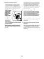
NordicTrack 14.0 Elliptical User manual
- Type
- User manual

Serial Number Decal
(on underside of frame)
USER’S MANUAL
Model No. NTEVEL19813.0
Serial No.
Write the serial number in the space
above for reference.
CAUTION
Read all precautions and instruc-
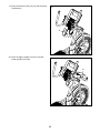
tions in this manual before using
this equipment. Keep this manual
for future reference.
www.iconeurope.com
CUSTOMER SERVICE
UNITED KINGDOM
Call: 08457 089 009
From Ireland: 053 92 36102
Website: www.iconsupport.eu
E-mail: [email protected]
Write:
ICON Health & Fitness, Ltd.
c/o HI Group PLC
Express Way
CASTLEFORD
WF10 5QJ
UNITED KINGDOM
AUSTRALIA
Call: 1800 993 770
E-mail: [email protected]
Write:
ICON Health & Fitness
PO Box 635
WINSTON HILLS NSW 2153
AUSTRALIA

2
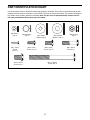
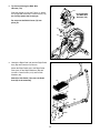
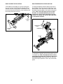
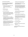
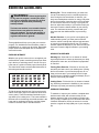
WARNING DECAL PLACEMENT
This drawing shows the location(s) of the warning
decal(s). If a decal is missing or illegible, see
the front cover of this manual and request a
free replacement decal. Apply the decal in the
location shown. Note: The decal(s) may not be
shown at actual size.
WARNING DECAL PLACEMENT . . . . . . . . . . . . . . . . . . . . . . . . . . . . . . . . . . . . . . . . . . . . . . . . . . . . . . . . . . . . . . .2
IMPORTANT PRECAUTIONS ..................................................................3
BEFORE YOU BEGIN. . . . . . . . . . . . . . . . . . . . . . . . . . . . . . . . . . . . . . . . . . . . . . . . . . . . . . . . . . . . . . . . . . . . . . . .4
PART IDENTIFICATION CHART. . . . . . . . . . . . . . . . . . . . . . . . . . . . . . . . . . . . . . . . . . . . . . . . . . . . . . . . . . . . . . . .5
ASSEMBLY . . . . . . . . . . . . . . . . . . . . . . . . . . . . . . . . . . . . . . . . . . . . . . . . . . . . . . . . . . . . . . . . . . . . . . . . . . . . . . . .6
THE CHEST HEART RATE MONITOR. . . . . . . . . . . . . . . . . . . . . . . . . . . . . . . . . . . . . . . . . . . . . . . . . . . . . . . . . .17
HOW TO USE THE ELLIPTICAL ..............................................................18
MAINTENANCE AND TROUBLESHOOTING ....................................................35
EXERCISE GUIDELINES ....................................................................37
PART LIST. . . . . . . . . . . . . . . . . . . . . . . . . . . . . . . . . . . . . . . . . . . . . . . . . . . . . . . . . . . . . . . . . . . . . . . . . . . . . . . .39
EXPLODED DRAWING. . . . . . . . . . . . . . . . . . . . . . . . . . . . . . . . . . . . . . . . . . . . . . . . . . . . . . . . . . . . . . . . . . . . . .41
ORDERING REPLACEMENT PARTS .................................................. Back Cover
RECYCLING INFORMATION ......................................................... Back Cover
TABLE OF CONTENTS
NORDICTRACK is a registered trademark of ICON IP, Inc.

3
IMPORTANT PRECAUTIONS
SAVE THESE INSTRUCTIONS
WARNING: To reduce the risk of burns, fire, electric shock, or injury to persons, read
all important precautions and instructions in this manual and all warnings on your elliptical before
using your elliptical. ICON assumes no responsibility for personal injury or property damage sus-
tained by or through the use of this product.
1. It is the responsibility of the owner to ensure
that all users of the elliptical are adequately
informed of all precautions.
2. Before beginning any exercise program,
consult your physician. This is especially
important for persons over age 35 or per-
sons with pre-existing health problems.
3. Use the elliptical only as described in this
manual.
4. The elliptical is intended for home use only.
Do not use the elliptical in a commercial,
rental, or institutional setting.
5. Keep the elliptical indoors, away from mois-
ture and dust. Do not put the elliptical in a
garage or covered patio, or near water.
6. Place the elliptical on a level surface, with at
least 3 ft. (0.9 m) of clearance in the front and
rear of the elliptical and 2 ft. (0.6 m) on each
side. To protect the floor or carpet from dam-
age, place a mat under the elliptical.
7. Inspect and properly tighten all parts regu-
larly. Replace any worn parts immediately.
8. Keep children under age 12 and pets away
from the elliptical at all times.
9. When connecting the power cord (see page
18), plug the power cord into a grounded
circuit.
10. Do not modify the power cord or use an
adapter to connect the power cord to an
improper receptacle. Keep the power cord
away from heated surfaces. Do not use an
extension cord.
11. Do not operate the elliptical if the power cord
or plug is damaged, or if the elliptical is not
working properly.
12. DANGER: Always unplug the power
cord and switch the power switch to the off
position when the elliptical is not in use and
before cleaning the elliptical. Servicing other
than the procedures in this manual should
be performed by an authorized service repre-
sentative only.
13. The elliptical should not be used by persons
weighing more than 397 lbs. (180 kg).
14. Wear appropriate clothes while exercising;
do not wear loose clothes that could become
caught on the elliptical. Always wear athletic
shoes for foot protection while exercising.
15. Hold the handlebars or the upper body arms
when mounting, dismounting, or using the
elliptical.
16. The heart rate monitor is not a medical
device. Various factors may affect the accu-
racy of heart rate readings. The heart rate
monitor is intended only as an exercise aid
in determining heart rate trends in general.
17. The elliptical does not have a freewheel; the
pedals will continue to move until the fly-
wheel stops. Reduce your pedaling speed in
a controlled way.
18. Keep your back straight while using the ellip-
tical; do not arch your back.
19. Over exercising may result in serious injury
or death. If you feel faint or if you experience
pain while exercising, stop immediately and
cool down.

4
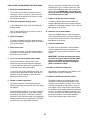
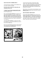
BEFORE YOU BEGIN
Thank you for selecting the revolutionary
NORDICTRACK
®
COMMERCIAL 14.0 elliptical. The
COMMERCIAL 14.0 elliptical provides an impressive
selection of features designed to make your workouts
at home more effective and enjoyable.
For your benet, read this manual carefully before
you use the elliptical. If you have questions after
reading this manual, please see the front cover of this
manual. To help us assist you, note the product model
number and serial number before contacting us. The
model number and the location of the serial number
decal are shown on the front cover of this manual.
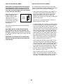
Before reading further, please familiarize yourself with
the parts that are labeled in the drawing below.
Resistance Control
Ramp Control
Heart Rate Monitor
Upper Body Arm
Wheel
Pedal
Pedal Knob
Console
Console Knob
Accessory Tray
Ramp
Handlebar
Length: 6 ft. 1 in. (185 cm)
Width: 2 ft. 1 in. (64 cm)
Weight: 229 lbs. (104 kg)
Ultrasonic
Sensor
(see step 11
on page 31)

5
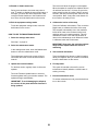
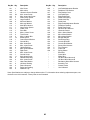
M8 x 35mm
Bolt (96)–4
M8 Jam Nut
(94)–4
Wave Washer
(95)–2
M8 x 23mm
Washer (98)–2
M4 x 16mm
Screw
(104)–17
M8 x 16mm
Screw (72)–19
M10 x 16mm
Screw (33)–2
M10 x 105mm
Screw (84)–2
M10 x 25mm
Washer (148)–2
M6 Washer
(90)–8
M6 x 14mm
Screw (121)–8
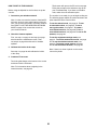
PART IDENTIFICATION CHART
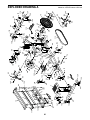
Use the drawings below to identify the small parts needed for assembly. The number in parentheses below each
drawing is the key number of the part, from the PART LIST near the end of this manual. The number following the
key number is the quantity needed for assembly. Note: If a part is not in the hardware kit, check to see if it
has been preassembled. Extra parts may be included.

6
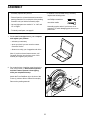
ASSEMBLY
• Assembly requires two persons.
• Place all parts in a cleared area and remove the
packing materials. Do not dispose of the packing
materialsuntilyounishallassemblysteps.
• Left and right parts are marked “L” or “Left” and
“R” or “Right.”
• To identify small parts, see page 5.
• In addition to the included tool(s), assembly
requires the following tools:
one Phillips screwdriver
one rubber mallet
Assembly may be easier if you have a set of
wrenches. To avoid damaging parts, do not use
power tools.
1
2. Set a sturdy piece of packing material under the
front of the Frame (1). Have a second person
hold the Frame to prevent it from tipping
while you complete this step.
Attach the Front Stabilizer (6) to the front of the
Frame (1) with two M10 x 105mm Screws (84).
Remove the packing material.
2
6
1
84
1. Go to www.iconsupport.eu on your computer
and register your product.
• activatesyourwarranty
• savesyoutimeifyoueverneedtocontact
Customer Service
• allowsustonotifyyouofupgradesandoffers
Note: If you do not have Internet access, call
Customer Service (see the front cover of this
manual) and register your product.

7
3
3. Set the Rear Stabilizer (5) on the floor behind
the Frame (1). Locate the wire tie in the Rear
Stabilizer.
See the inset drawing. Tie the end of the wire
tie to the Sensor Wire Harness (155).
Pull the other end of the wire tie until the Sensor
Wire Harness (155) is routed through the Rear
Stabilizer (5).
1
5
155
Wire
Tie
Wire
Tie
155
Wire Tie
4
4. Tip: Avoid pinching the Sensor Wire
Harness (155).
Set a sturdy piece of packing material under the
rear of the Frame (1). Have a second person
hold the Frame to prevent it from tipping
while you complete this step.
Insert the Rear Stabilizer (5) into the Frame (1).
Attach the Rear Stabilizer with four M8 x 16mm
Screws (72); start all four Screws, and then
tighten them.
Remove the packing material.
72
155
72
1
5
Avoid pinching
the Sensor Wire
Harness (155)
5. Untie and discard the wire tie (not shown) on the
Sensor Wire Harness (155).
While a second person holds the Rear Stabilizer
Cover (2) near the Rear Stabilizer (5), connect
the wire on the Ultrasonic Sensor (147) to the
Sensor Wire Harness (155). Insert the excess
wire into the Rear Stabilizer.
Tip: Avoid pinching the Sensor Wire Harness
(155). Press the four Mounts (117) on the under-
side of the Rear Stabilizer Cover (2) into the
Rear Stabilizer (5).
5
2
5
155
147
117
Avoid pinching
the Sensor Wire
Harness (155)

8
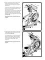
6
6. Identify the Lower Upright Cover (80), which has
a large oval hole in it.
Orient the Lower Upright Cover (80), the Shield
Cover (75), and the Upright (4) as shown. Slide
the Lower Upright Cover and the Shield Cover
upward onto the Upright.
80
75
4
7
7. While a second person holds the Upright (4)
near the Frame (1), locate the wire tie in the
Upright.
See the inset drawing. Tie the lower end of the
wire tie to the Main Wire Harness (110).
Pull the upper end of the wire tie until the Main
Wire Harness (110) is routed through the
Upright (4).
Tip: To prevent the Main Wire Harness (110)
from falling into the Upright (4), secure the
Main Wire Harness with the wire tie.
110
4
1
110
Wire Tie
Wire Tie
Wire
Tie

9
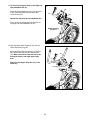
8. Tip: Avoid pinching the Main Wire
Harness (110).
Slide the Upright (4) onto the Frame (1). Attach
the Upright with seven M8 x 16mm Screws (72);
do not fully tighten the Screws yet.
Do not press the Shield Cover (75) into
place yet.
8
1
72
72
72
4
75
110
Avoid pinching
the Main Wire
Harness (110)
9
49
58
90
90
121
121
14
44
139
9. Identify the Right Pedal (49) and the Right Pedal
Arm (58) and orient them as shown.
Attach the Right Pedal (49) to the Right Pedal
Plate (139) on the Right Pedal Arm (58) with
four M6 x 14mm Screws (121) and four M6
Washers (90).
Attach the Left Pedal (14) to the Left Pedal
Arm (44) in the same way.

10
10
10. Using a plastic bag to keep your fingers clean,
apply a generous amount of the included
grease to the Arm Axle (35) and to two Wave
Washers (95).
Insert the Arm Axle (35) into the Upright (4) and
center it. Then, slide a Wave Washer (95) onto
each end of the Arm Axle.
With the help of a second person, slide the Right
Upper Body Leg (36) onto the right side of the
Arm Axle (35) and insert the axle on the Right
Pedal Arm (58) into the Right Roller Arm (45) at
the same time.
Repeat these actions on the left side of the
elliptical.
11. Tighten an M8 x 16mm Screw (72) with an M8
x 23mm Washer (98) into each end of the Arm
Axle (35) at the same time.
Then, tighten an M10 x 16mm Screw (33) with
an M10 x 25mm Washer (148) into the Right
Roller Arm (45) and the Right Pedal Arm (58).
Then, tighten the indicated M8 x 16mm
Screw (72).
Repeat these actions on the left side of the
elliptical.
35
Grease
Grease
95
95
36
46
58
44
44
46
12
12
45
Grease
4
11
35
98
148
98
72
45
33
72
58
72

11
12
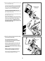
12. Tip: Avoid pinching the wires in the Right and
Left Handlebars (83, 87).
Attach the Right Handlebar (83) to the right side
of the Console Bracket (62) with three M8 x
16mm Screws (72).
Repeat this step with the Left Handlebar (87).
Then, remove the packaging from the wires on
the Right and Left Handlebars (83, 87).
13
13. Slide the Right Upper Body Arm (61) onto the
Right Upper Body Leg (36).
Attach the Right Upper Body Arm (61) with two
M8 x 35mm Bolts (96) and two M8 Jam Nuts
(94). Make sure that the Jam Nuts are in the
hexagonal holes in the Right Upper Body
Arm.
Attach the Left Upper Body Arm (47) in the
same way.
Avoid pinching
the wires
72
83
96
36
61
47
94
87
62
Hexagonal Holes

12
14
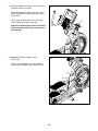
15
15. Note: For clarity, the Console and the wiring
are not shown in this step.
Tip: It may be necessary to turn the
Console Knob (52) and adjust the angle of
the Console Bracket (62).
Attach the Upper Handlebar Cover (56) to the
Right and Left Handlebars (83, 87) and to the
Console Bracket (62) with three M4 x 16mm
Screws (104); start all three Screws, and then
tighten them.
Make sure that the wiring (not shown) is
inside the Upper Handlebar Cover (56).
Then, press the Lower Handlebar Cover (60)
onto the Upper Handlebar Cover (56).
14. Have a second person hold the Console (7) near
the Console Bracket (62).
Connect the Ground Wire (119) to the matching
wire on the Console (7). Then, insert all of the
wires on the Console downward through the
indicated hole in the Console Bracket (62).
Tip: Avoid pinching the wires. Attach the
Console (7) to the Console Bracket (62) with four
M4 x 16mm Screws (104).
Untie and discard the wire tie (not shown) on the
Main Wire Harness (110).
See the inset drawing. Connect the Main Wire
Harness (110), the Receiver Wire Harness (146),
and the two indicated wires to the matching
wires on the Console (7). Make sure to con-
nect the wire that has a tag to the wire on the
Console that has a tag.
104
60
52
62
56
87
104
Hole
146
7
7
83
104
104
119
62
Avoid pinching
the wires
110
Wires

13
16
16. Slide the Lower Upright Cover (80) upward, and
attach it to the Upright (4) with two M4 x 16mm
Screws (104).
17
17. Attach the Accessory Tray Base (8) to the
Upright (4) with two M4 x 16mm Screws (104).
18. See the left drawing. Locate the receiver in
the Accessory Tray Base (8). Insert the wire on
the receiver into the indicated hole in the Lower
Upright Cover (80).
See the right drawing. Locate the Receiver
Wire Harness (146), which is attached to the
Upright (4) with wire ties. Connect the Receiver
Wire Harness to the wire on the receiver.
104
104
Wire
Top View
Hole
80
8
80
8
4
4
Receiver
146
Wire
4
18

14
19
19. Press the Accessory Tray (37) into the Accessory
Tray Base (8).
20
20. Press the Upper Upright Cover (91) onto the
Lower Upright Cover (80).
8
37
91
80

15
21
21. Identify the Right Arm Upper Cover (67) and the
Right Arm Lower Cover (68).
Attach the Right Arm Upper Cover (67) to the
Right Upper Body Leg (36) with an M4 x 16mm
Screw (104).
Then, press the Right Arm Lower Cover (68)
onto the Right Arm Upper Cover (67).
Attach the Left Arm Upper Cover (not shown)
and the Left Arm Lower Cover (not shown) in
the same way.
67
36
68
104
22. See step 8. Tighten the M8 x 16mm
Screws (72).
Then, press the Shield Cover (75) downward
onto the Left and Right Front Shields (73, 74).
22
75
73, 74

16
24. Make sure that all parts are properly tightened before you use the elliptical. Note: Extra parts may be
included. Place a mat beneath the elliptical to protect the floor.
23. While a second person tips the elliptical to the
left and holds it, attach a Stabilizer Cap (134)
to the right side of the Frame (1) with two M4 x
16mm Screws (104).
Next, tighten a Leveling Foot (92) into the Frame
(1) in the indicated location.
Repeat this step on the left side of the
elliptical.
23
1
92
104
134

17
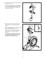
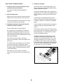
HOW TO PUT ON THE HEART RATE MONITOR
The heart rate
monitor consists of
a chest strap and a
sensor. Insert the
tab on one end of
the chest strap into
the hole in one end
of the sensor as
shown. Then, press
the end of the sen-
sor under the buckle
on the chest strap.
The tab should be
flush with the front of
the sensor.
The heart rate moni-
tor must be worn
under your clothes,
tight against your
skin. Wrap the heart
rate monitor around
your chest in the
location shown.
Make sure that
the logo is right-
side-up. Then, attach the other end of the chest strap
to the sensor. Adjust the length of the chest strap, if
necessary.
Pull the sensor away from your body a few inches and
locate the two electrode areas, which are covered by
shallow ridges. Using saline solution such as saliva or
contact lens solution, wet the electrode areas. Then,
return the sensor to a position against your chest.
CARE AND MAINTENANCE
• Thoroughly dry the sensor with a soft towel after
each use. Moisture may keep the sensor activated,
shortening the life of the battery.
• Store the heart rate monitor in a warm, dry place. Do
not store the heart rate monitor in a plastic bag or
other container that may trap moisture.
• Do not expose the heart rate monitor to direct sun-
light for extended periods of time; do not expose it to
temperatures above 122° F (50° C) or below 14° F
(-10° C).
• Do not excessively bend or stretch the sensor when
using or storing the heart rate monitor.
• To clean the sensor, use a damp cloth and a small
amount of mild soap. Then, wipe the sensor with a
damp cloth and thoroughly dry it with a soft towel.
Never use alcohol, abrasives, or chemicals to clean
the sensor. Hand wash and air dry the chest strap.
TROUBLESHOOTING
If the heart rate monitor does not function properly, try
the steps below.
• Make sure that you are wearing the heart rate moni-
tor as described at the left. If the heart rate monitor
does not function when positioned as described,
move it slightly lower or higher on your chest.
• If heart rate readings are not displayed until you
begin perspiring, rewet the electrode areas.
• For the console to display heart rate readings, you
must be within arm’s length of the console.
• If there is a battery cover on the back of the sensor,
replace the battery with a new battery of the same
type.
• The heart rate monitor is designed to work with
people who have normal heart rhythms. Heart rate
reading problems may be caused by medical condi-
tions such as premature ventricular contractions
(pvcs), tachycardia bursts, and arrhythmia.
• The operation of the heart rate monitor can be
affected by magnetic interference from high power
lines or other sources. If you suspect that magnetic
interference is causing a problem, try relocating the
fitness equipment.
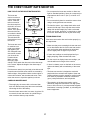
THE CHEST HEART RATE MONITOR
Sensor
Tab
Buckle
Chest
Strap
Tabs
Sensor

18
HOW TO USE THE ELLIPTICAL
HOW TO PLUG IN THE POWER CORD
This product must be earthed. If it should malfunc-
tion or break down, earthing provides a path of least
resistance for electric current to reduce the risk of
electric shock. This product’s power cord has an
equipment-earthing conductor and an earthing plug.
IMPORTANT: If the power cord is damaged, it must
be replaced with a manufacturer-recommended
power cord.
Follow the steps below to plug in the power cord.
1. Plug the indicated end of the power cord into the
socket on the frame.
2. Plug the power cord into an appropriate outlet that
is properly installed and earthed in accordance with
all local codes and ordinances.
DANGER: Improper connection of
the equipment-earthing conductor can result
in an increased risk of electric shock. Check
with a qualified electrician or serviceman if
you are in doubt as to whether the product
is properly earthed. Do not modify the plug
provided with the product—if it will not fit
the outlet, have a proper outlet installed by a
qualified electrician
IT
FR/SP
UK
GR
RU
HU
AUS
Socket on Frame
IT
FR/SP
UK
GR
RU
HU
AUS
IT
FR/SP
UK
GR
RU
HU
AUS
Outlet
UK
Australia
Outlet
Power Cord

19
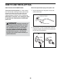
HOW TO MOVE THE ELLIPTICAL
Due to the size and weight of the elliptical, moving
it requires two persons. Stand in front of the elliptical,
hold the upright, and place one foot against one of the
wheels. Pull on the upright and have a second person
lift the rear stabilizer until the elliptical will roll on the
wheels. Carefully move the elliptical to the desired
location,andthenlowerittotheoor.
HOW TO ADJUST THE POSITIONS OF THE
PEDALS
Each pedal can be adjusted to several positions. To
adjust each pedal, lift the pedal and turn the pedal
knob beneath the pedal. Make sure to adjust both
pedals to the same position.
HOW TO ADJUST THE CONSOLE
The console can be adjusted to several angles. To
adjust the console, turn the console knob until the con-
sole is at the desired angle.
Place
your foot
here
Pull on
the upright
Pedal Knob
Console Knob
Lift here

20
HOW TO LEVEL THE ELLIPTICAL
If the elliptical rocks slightly on your floor during use,
turn one or both of the leveling feet beneath the rear
stabilizer until the rocking motion is eliminated. Then,
turn the leveling feet beneath the center stabilizer until
the leveling feet touch your floor.
HOW TO EXERCISE ON THE ELLIPTICAL
To mount the elliptical, hold the upper body arms or
the handlebars and step onto the pedal that is in the
lower position. Then, step onto the other pedal. Push
the pedals until they begin to move with a continuous
motion. Note: The crank arms can turn in either
direction. It is recommended that you turn the
crank arms in the direction shown by the arrow;
however, for variety, you can turn the crank arms
in the opposite direction.
To dismount the elliptical, wait until the pedals come to
a complete stop. Note: The elliptical does not have
a free wheel; the pedals will continue to move until
the ywheel stops. When the pedals are stationary,
stepoffthehigherpedalrst.Then,stepoffthelower
pedal.
Leveling
Feet
Leveling
Foot
Pedals
Crank
Arm
Upper Body
Arms
Handlebars
Page is loading ...
Page is loading ...
Page is loading ...
Page is loading ...
Page is loading ...
Page is loading ...
Page is loading ...
Page is loading ...
Page is loading ...
Page is loading ...
Page is loading ...
Page is loading ...
Page is loading ...
Page is loading ...
Page is loading ...
Page is loading ...
Page is loading ...
Page is loading ...
Page is loading ...
Page is loading ...
Page is loading ...
Page is loading ...
Page is loading ...
Page is loading ...
-
 1
1
-
 2
2
-
 3
3
-
 4
4
-
 5
5
-
 6
6
-
 7
7
-
 8
8
-
 9
9
-
 10
10
-
 11
11
-
 12
12
-
 13
13
-
 14
14
-
 15
15
-
 16
16
-
 17
17
-
 18
18
-
 19
19
-
 20
20
-
 21
21
-
 22
22
-
 23
23
-
 24
24
-
 25
25
-
 26
26
-
 27
27
-
 28
28
-
 29
29
-
 30
30
-
 31
31
-
 32
32
-
 33
33
-
 34
34
-
 35
35
-
 36
36
-
 37
37
-
 38
38
-
 39
39
-
 40
40
-
 41
41
-
 42
42
-
 43
43
-
 44
44


NordicTrack 14.0 Elliptical User manual
- Type
- User manual
Ask a question and I''ll find the answer in the document
Finding information in a document is now easier with AI
Related papers
-
ProForm 23946-MX.0 User manual
-
NordicTrack NTEL71320-INT User manual
-
-
-
-
-
-
-
-
Other documents
-
AeroWorks EDGE 540 Assembly Manual
-
Pro-Form TRAINER 7.0 PFEVEL10716.0 User manual
-
-
-
-
ProForm PFEL31115 User manual
-
 Epic Fitness A30e Elliptical User manual
-
ProForm PFCCEL04912.0 User manual
-
-
