Page is loading ...

Sales 800-633-0405
1
2000
WARNING: To minimize the risk of potential safety problems, you
should follow all applicable local and national codes that regulate
the installation and operation of your equipment. These codes vary
from area to area and it is your responsibility to determine which
codes should be followed, and to verify that the equipment, instal-
lation, and operation are in compliance with the latest revision of
these codes.
Equipment damage or serious injury to personnel can result
from the failure to follow all applicable codes and standards. We
do not guarantee the products described in this publication are
suitable for your particular application, nor do we assume any
responsibility for your product design, installation, or operation.
If you have any questions concerning the installation or opera-
tion of this equipment, or if you need additional information, please
call Technical Support at 770-844-4200.
This publication is based on information that was available at
the time it was printed. At Automationdirect.com® we constantly
strive to improve our products and services, so we reserve the right
to make changes to the products and/or publications at any time
without notice and without any obligation. This publication may also
discuss features that may not be available in certain revisions of
the product.
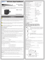
P2-04B, P2-07B, P2-11B,
P2-15B Bases
The P2-04B, P2-07B, P2-11B, and P2-15B are multi-slot I/O bases
for use with the Productivity2000 system.
Document Name Edition/Revision Date
P2-BASES-DS
1st Ed., Rev A
5/14/2018
Copyright 2018, Automationdirect.com Incorporated/All Rights Reserved Worldwide
Warranty: Thirty-day money-back guarantee. Two-year limited replacement.
(See www.productivity2000.com for details).
Warning .........................................................................................................1
General Specifications ..................................................................................2
Base Specifications ......................................................................................2
Base Configuration and Dimensions .............................................................3
Panel Mounting Requirements ......................................................................4
DIN Rail Installation ......................................................................................6
Agency Approvals ........................................................................................7
Safety Guidelines .........................................................................................8
Plan for Safety .............................................................................................8
www.productivity2000.com

2
Tech Support 770-844-4200
General Specifications
Operating Temperature 0° to 60°C (32° to 140°F)
Storage Temperature -20° to 70°C (-4° to 158°F)
Humidity 5 to 95% (non-condensing)
Environmental Air No corrosive gases permitted
Vibration IEC60068-2-6 (Test Fc)
Shock IEC60068-2-27 (Test Ea)
Heat Dissipation 3W
Agency Approvals
UL508 file E139594, Canada & USA
CE (EN61131-2*)
Weight
P2-04B: 204g (7.2oz)
P2-07B: 294g (10.4oz)
P2-11B: 430g (15.2oz)
P2-15B: 521g (18.4oz)
*Meets EMC and Safety requirements. See the D.O.C. for details.
Base Specifications
Input or Output Modules per Base 4, 7, 11, or 15
Power Supply Slots 1 (P2-01AC)
CPU Slots 1 (P2-550)
Module Types Supported Discrete, analog and specialty
Module Placement Restrictions
None. Any I/O module may be installed in
any I/O slot without power supply budget or
module type restrictions.
I/O Module Hot Swap Support
Yes. (All discrete and analog modules can be
software enabled for Hot Swap operation)
Module Keying Electronic to slot
Maximum Number of Local Bases 1
www.productivity2000.com

3
Sales 800-633-0405
Base Configuration and Dimensions
Rotary Switches are for
setting the Remote Slave
Node Address. See
P2-RS insert for details.
Note: If CPU is installed
switch settings are
ignored.
or or
C
P
U
AC
Power
Supply
R
e
m
o
t
e
I/O
DC
Power
Supply
Discrete,
Analog and
Specialty I/O
8.75”
inches
[mm]
4.37
[111]
7.54
[191.5]
18.37
[466.6]
13.88
[352.5]
17.82
[452.6]
14.43
[366.5]
9.94
[252.5]
5.06
[128.5]
5.06
[128.5]
5.06
[128.5]
5.06
[128.5]
6.99
[177.5]
10.49
[266.4]
4.67
[118.6]
P2-04B
P2-07B
P2-11B
P2-15B
P2-04B
P2-07B
P2-11B
P2-15B
P2-04B
P2-07B
P2-11B
P2-15B
4.67
[118.6]
4.67
[118.6]
4.67
[118.6]
[
]
www.productivity2000.com

4
Tech Support 770-844-4200
Panel Mounting Requirements
AIRFLOW
OK
2”
50mm
min
2”
50mm
min
7.2”
183mm
min
3”
76mm
min
3”
76mm
min
Enclosures
Your selection of a proper enclosure is important to ensure
safe and proper operation of your Productivity2000 system.
Applications for the Productivity2000 system vary and may require
additional hardware considerations. The minimum considerations
for enclosures include:
• Conformance to electrical standards
• Protection from the elements in an industrial
environment
• Common ground reference
• Maintenance of specified ambient temperature
• Access to the equipment
• Security or restricted access
• Sufficient space for proper installation and
maintenance of the equipment
Mounting Position
Mount the bases horizontally, as shown in the illustration, to provide
proper ventilation. Do not mount the bases vertically, upside down,
or on a flat horizontal surface.
Mounting Clearances
Provide a minimum clearance of 2” (50mm) between the bases and
all sides of the enclosure. Allow extra door clearance for operator
panels and other door mounted items. There should be a minimum
of 3” (76mm) clearance between the base and any wire duct, and
a minimum of 7.2” (183mm) from base to base in a multiple base
installation.
2”
NOTE: Add 2" to mounting
depth when using ZIPLink
cable.
2
”
N
O
TE:
A
d
d
depth whe
n
c
a
bl
e
.
www.productivity2000.com

5
Sales 800-633-0405
2”
50mm
min
2”
50mm
min
7.2”
183mm
min
3”
76mm
min
3”
76mm
min
Grounding
A good common ground reference (earth ground) is essential for
proper operation of the Productivity2000 system. One side of all
control circuits, power circuits and the ground lead must be prop-
erly connected to earth ground by either installing a ground rod in
close proximity to the enclosure or by connecting to the incoming
power system ground. There must be a single-point ground (i.e.
copper bus bar) for all devices in the enclosure that require an
earth ground.
Temperature Considerations
The Productivity2000 system should be installed within the oper-
ating temperature specifications as listed in this document. If the
temperature deviates above or below the specification, measures
such as cooling or heating the enclosure should be taken to main-
tain the specification.
Power Considerations
The Productivity2000 system is designed to be powered by the
110/220 VAC power supply (P2-01AC). The Productivity2000 has
achieved CE certification without requiring EMF/RFI line noise
filters on the AC power supply. Please review the “EU Directives”
document, located in the User Manual or at
www.productivity2000.com, for applications which require CE
Compliance.
www.productivity2000.com

6
Tech Support 770-844-4200
DIN Rail Installation
Using Mounting Rails
The Productivity2000 bases can be secured to the cabinet using
mounting rails. You should use rails that conform to DIN EN
standard 50 022. Refer to our catalog for a complete line of DIN
rail, DINnectors and DIN rail mounted apparatus. These rails are
approximately 35mm high, with a depth of 7.5mm. If you mount the
base on a rail, you should also consider using end brackets on each
end of the rail. The end brackets help keep the base from sliding
horizontally along the rail. This helps minimize the possibility of
accidentally pulling the wiring loose.
If you examine the bottom of the base, you’ll notice retaining
clips. To secure the base to a DIN rail, place the base onto the rail
and gently push up on the retaining clips. The clips lock the base
onto the rail.
To remove the base, pull down on the retaining clips, slightly
lift up the base, and pull it away from the rail.
Rotate base
into position.
Hook base
onto DIN rail at
top of mount-
ing slot.
Gently push up
retaining clips.
1
2
3
Retaining Clips
DIN Rail
Dimensions
7.5 mm
35 mm
End Bracket (Part No. DN-EB35)
DIN Rail (Part No. DN-R35S1)
www.productivity2000.com

Sales 800-633-0405
7
Agency Approvals
Some applications require agency approvals for particular
components. The Productivity2000 agency approvals are listed
below:
• UL (Underwriters’ Laboratories, Inc.)
• CUL (Canadian Underwriters’ Laboratories, Inc.)
• CE (European Economic Union)
Note: See the “EU Directive” topic in the Productivity2000 User manual.
Information can also be obtained at: www.productivity2000.com
www.productivity2000.com

8
Tech Support 770-844-4200
Safety Guidelines Plan for Safety
WARNING: Providing a safe operating environment for personnel
and equipment is your responsibility and should be your primary
goal during system planning and installation. Automation systems
can fail and may result in situations that can cause serious injury to
personnel or damage to equipment. Do not rely on the automation
system alone to provide a safe operating environment. You should
use external electro-mechanical devices, such as relays or limit
switches, that are independent of the P2000 application to provide
protection for any part of the system that may cause personal injury
or damage. Every automation application is different, so there may
be special requirements for your particular application. Make sure
you follow all national, state, and local government requirements for
the proper installation and use of your equipment.
The best way to provide a safe operating environment is to make
personnel and equipment safety part of the planning process. You
should examine every aspect of the system to determine which
areas are critical to operator or machine safety. If you are not
familiar with automated system installation practices, or your
company does not have established installation guidelines, you
should obtain additional information from the following sources.
• NEMA — The National Electrical Manufacturers Association,
located in Washington, D.C., publishes many different docu-
ments that discuss standards for industrial control systems.
You can order these publications directly from NEMA. Some of
these include: ICS 1, General Standards for Industrial Control
and Systems ICS 3, Industrial Systems ICS 6, Enclosures for
Industrial Control Systems
• NEC — The National Electrical Code provides regulations
concerning the installation and use of various types of elec-
trical equipment. Copies of the NEC Handbook can often be
obtained from your local electrical equipment distributor or your
local library.
• Local and State Agencies — many local governments and state
governments have additional requirements above and beyond
those described in the NEC Handbook. Check with your local
Electrical Inspector or Fire Marshall office for information.
Safety Techniques
The publications mentioned provide many ideas and requirements
for system safety. At a minimum, you should follow these regula-
tions. Using the techniques listed below will further help reduce the
risk of safety problems.
• Orderly system shutdown sequence in the P2000 control
program.
• Emergency stop switch for disconnecting system power.
www.productivity2000.com
/