VADDIO WallView PRO H900 Installation and User Manual
- Category
- Camera accessories
- Type
- Installation and User Manual
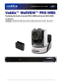
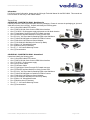
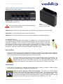
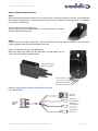
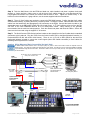
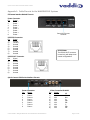
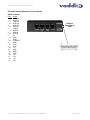
VADDIO WallView PRO H900 is a system designed for easier cable extension installation and integration. It was built and adapted for use with the Sony BRC-H900 3-CMOS HD pan/tilt/zoom robotic camera. The system is capable of accepting the high definition resolution video that the BRC-H900 camera outputs, (HD - 1080i/59.94/50 field/s or 720p59.94/50 frames/s component video), as well as higher resolutions up to 1080p/60.
VADDIO WallView PRO H900 is a system designed for easier cable extension installation and integration. It was built and adapted for use with the Sony BRC-H900 3-CMOS HD pan/tilt/zoom robotic camera. The system is capable of accepting the high definition resolution video that the BRC-H900 camera outputs, (HD - 1080i/59.94/50 field/s or 720p59.94/50 frames/s component video), as well as higher resolutions up to 1080p/60.


-
 1
1
-
 2
2
-
 3
3
-
 4
4
-
 5
5
-
 6
6
-
 7
7
-
 8
8
-
 9
9
-
 10
10
-
 11
11
-
 12
12
-
 13
13
-
 14
14
-
 15
15
-
 16
16


VADDIO WallView PRO H900 Installation and User Manual
- Category
- Camera accessories
- Type
- Installation and User Manual
VADDIO WallView PRO H900 is a system designed for easier cable extension installation and integration. It was built and adapted for use with the Sony BRC-H900 3-CMOS HD pan/tilt/zoom robotic camera. The system is capable of accepting the high definition resolution video that the BRC-H900 camera outputs, (HD - 1080i/59.94/50 field/s or 720p59.94/50 frames/s component video), as well as higher resolutions up to 1080p/60.
Ask a question and I''ll find the answer in the document
Finding information in a document is now easier with AI
Related papers
-
VADDIO Quick-Connect CCU H900 Installation and User Manual
-
-
-
-
-
VADDIO CLEARVIEW HD-18 Installation and User Manual
-
-
-
-
Other documents
-
 Cerro 630-WRKBRKT1 Operating instructions
-
Kramer Electronics CP-GM-15-5BMKIT Datasheet
-
Cannon BU-46H User manual
-
Kramer Electronics C-SM/2BF-1 Datasheet
-
-
 Sony Série BRC-H900 User manual
-
 Chip PC CDC01927 User manual
-
Rev-A-Shelf CVR-14-SN Installation guide
-
Sony BRC-300 Specification
-
Vinten PTZ Mounting Solutions Operator Guide


