
RSA5BUP (Options 65, 66, and 6566)
RSA5UP (Option 5566)
RSA5100A and RSA5100B Series Real-Time Signal Analyzers
Digital I and Q Outputs and Zero Span Output Upgrades
ZZZ
Instructions
xx
www.tektronix.com
*
P075106100*
075-1061-00

Copyright © Tektronix. All rights reserved. Licensed software products are owned by Tektronix or its subsidiaries
or suppliers, and are protected by national copyright laws and international treaty provisions.
Tektronix products are covered by U.S. and foreign patents, issued and pending. Information in this publication
supersedes that in all previously published material. Specifications and price change privileges reserved.
TEKTRONIX and TEK are registered trademarks of Tektronix, Inc.

Service safety summary
Only qualified personnel should perform service procedures. Read this Service
Safety Summary and the General Safety Summary located in the Service M anual
before perfo
rming any service procedures.
Do Not Service Alone. Do not perform internal service or adjustments of this
product unless another person capable of rendering first aid and resuscitation is
present.
Disconnec
tPower. To avoid e lectric shock, switch off the instrument power, then
disconnect the power cord from the mains power.
UseCareWhenServicingWithPowerOn. Dangerousvoltagesorcurrentsmay
exist in this product. Disconnect power, remove battery (if applicable), and
disconnect test leads before removing protective panels, soldering, or replacing
compon
ents.
To avoid electric shock, d o not touch exposed connections.
RSA5100A/B Series Digital I/Q and Zero Span Upgrades 1

Kit description
Kit description
This kit describes the installation of the following Options:
RSA5100B Ser
ies.
Option 65: Digital I and Q Outputs
Option 66: Zero Span Output
Option 6566: Digital I and Q Outputs and Zero Span Output
RSA5100A Series.
Option 5566: Digital I and Q Outputs and Zero Span Output
Products
RSA5103B. All serial numbers
RSA5106B. All serial numbers
RSA51
15B. Allserialnumbers
RSA5126B. All serial numbers
RSA5103A. All serial numbers
RSA
5106A. All serial numbers
RSA5115A. Allserialnumbers
RSA5126A. All serial numbers
2 RSA5100A/B Series Digital I/Q and Zero Span U pgrades

Kit description
Kit parts list
The following table provides a list of parts contained in this k it. The kit contains
the same parts, regardless o f which of the three options you ordered. The actual
option (or options) available is controlled with the option key provided in the kit.
Quantity Part number Description
1 075-1061-X
X
MANUAL, TECH INSTALLATION, RSA5BUP OPTIONS 65,
66, 6566
1 171-2191-
XX
MANUAL,TECH; SVCPT-UPG; TEKTRONIX
SUPPLEMENTAL INFORMATION SHEET FO R
THE PEOPLE
S REPUBLIC OF CHINA; CHINA ROHS
2 174-5106-XX
CABLE, ASSEMBLY (I AND Q O UT, PANEL MOUNT),
SAFETY CO
NTROLLED
2 174-5195-XX
CABLE ASSY ELEC: 2X 50P MDR CONN. 1.5M L, 18
TWIST PA
IR, 100 OHM, 1 I/O, 13 GND, W/SHIELD
NOTE. These cables are not needed to install the Option.
They are supplied for external connections to the I and Q
Output
connectors.
1 174-5213-XX
CABLE ASSY, RIBBON; STATIC GROUND, 1X2; SAFETY
CONTR
OLLED
1 174-6418-XX
CABLE, COAX BNC-ST TO SMB-RA
1 200-
5317-XX
COVER, REAR PANEL, OPTION (I AND Q / ZERO SPAN)
4 211-0450-XX
SCRE
W, MACHINE ; 2.5MM X 0.45 X 6MM, PNH, STEEL,
ZINC PLATED, T8 TORX DRIVE
8 211-1050-XX
SCR
EW, MACHINE; 6-32 X 0.312 L, PNH, STEEL, ZINC
FINISH, T15
1 863-0955-XX
CK
T BD SUBASSY; REAL TIME IQ AND LOG VIDEO
OUTPUT, FUNCTIONALLY TESTED
1
N
/A
L
ABEL, EXPORT CO NTROL CLASSIFICATION
NOTE. Export c ontrol label only applies to RSA5100B
Series instruments when installing Option 65 or Option 6566.
1
N/A LABEL, MANUFACTURED; OPTION KEY UPGRADE
LABEL
1
N/A LABEL, MANUFACTURED; PRODUCT LABEL, SAFETY
CONTROLLED
RSA5100A/B Series Digital I/Q and Zero Span Upgrades 3

Installation instructions
Installation instructions
This section contains all procedures needed to install the required components.
Minimum tool
and equipment list
The following tools are required to for installation of this k it. All tools are
standard tools that are readily available.
Item Name Description
1.
Screwdriver handle (magnetic)
Torque driver. Accepts 14 inch
hex-head driver tips
2.
T8 TORX tip TORX driver tip for T-8 size screw
heads
3.
T15 TORX tip TORX driver tip for T-15 size screw
heads
4.
T20 TORX tip TORX driver tip for T-20 size screw
heads
5.
5/8" hex wrench Open end wrench to install BNC
connector
6.
5/32" hex wrench
NOTE. Only needed for early models
of the RSA5100A Series instruments.
Hex wrench to remove Allen head
screws at front of top cover
These instructions are for qualified service personnel who are familiar
with servicing the product. If you need further details for disassembling or
reassembling the product, refer to the product’s Service Manual.
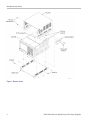
Rem
ove cosmetic covers and shield
NOTE. Right-side or left-side references in these instructions assume you are
viewing the instrument from the front panel.
WARNING. To avoid electric shock, switch off the instrument power, then
disconnect the power cord from the mains power. Failure to do so can cause
injury or death.
1. Remove the power cord.
2. If it is installed, pull the front cover off the instrument.
4 RSA5100A/B Series Digital I/Q and Zero Span U pgrades

Installation instructions
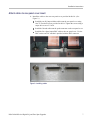
3. Remove the two T
15 Torx-head screw s that secure the plastic carrying handle
to the side o f the instrument. (It is not necessary to remove the black metal
handles.) (See Figure 1.)
4. Remove four T15 Torx-head screws along each side that secure the top and
bottom covers to the instrument, and two T20 Torx-head screws near the front
edge of the top cover (next to the folding handles).
NOTE. Early models of the RSA5100A Series instruments used four 5/32″ Allen
socket cap screws in place of the T15 Torx-head screws.
5. Remove the top and bottom covers. Remove the top cover by pulling straight
back about 1 inch. Then pull out on the sides of the top cover outward,
flexing t
hem slightly to clear the instrument chassis, and pull it away from the
instrument.
6. Remove t
he eighteen T15 Torx-head screws that secure the top shield to the
chassis and remove the shield.
RSA5100A/B Series Digital I/Q and Zero Span Upgrades 5

Installation instructions
Figure 1: Remove covers
6 RSA5100A/B Series Digital I/Q and Zero Span U pgrades

Installation instructions
Attach cables to rear-panel cover insert
1. Install the cables to the new rear-panel cover p rovided in this kit. (See
Figure 2.)
Install the two IQ Output ribbon cables onto the rear panel cover using
four T8 Torx-head screws provided in the kit. Tighten the screws using a
torque driver set to 5.5 in-lb.
Install the Ground cable onto the spade connector on the rear-panel cover.
Install the Zero Span Output BNC cable to the rear-panel cover. Use the
BNC washer and 5/8″ nut that is provided with the BNC connector.
Fig
ure 2 : Installing cables
RSA5100A/B Series Digital I/Q and Zero Span Upgrades 7

Installation instructions
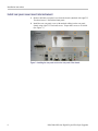
Install rear panel cover insert into instrument
1. Remove the blank, rear-panel cover from the chassis (attached with eight T15
Torx-head screws). Discard the blank panel.
2. Install the new rear-panel cover (with attached cabling) on the rear panel
chassis using eight T15 Torx-head screws. Torque these screws to 10.0 in/lb.
(See Figure 3.)
Figure
3: Installing the rear panel cover on the rear panel of the chassis
8 RSA5100A/B Series Digital I/Q and Zero Span U pgrades

Installation instructions
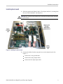
Install option board
1. Slide the option board (Digital I and Q / Zero Span) into Slot 3 (counting from
the rear of the instrument). (See Figure 4.)
CAUTION. Be careful not to bend the pins on the Interface Board when installing
the option board.
Figur
e 4 : Installing the option board
2. Conn
ect t he ca bles from the rear-panel cover to the Option board. (See
Figure 5.)
Con
nect the 2-wire ground cable.
Connect the I and Q output cables.
Connect the Zero Span output cable.
RSA5100A/B Series Digital I/Q and Zero Span Upgrades 9

Installation instructions
Figure 5: Connecting the output cables
Reinstall top shield and cosmetic covers
1. Place t
he instrument on its bottom feet.
2. Place the top shield on top of the instrument and reinstall the e ighteen T15
Torx-
head screws.
3. Place the instrument on its rear feet, so the front panel is facing up and the
top i
s toward you.
4. Place the top cover over the top of the instrument and slide it toward the
fro
nt panel. Make sure that the top cover wraps around the flanges on the
rear panel on all three sides.
5. Re
install the four T20 Torx-head screws (two on each side) near the front
edge of the top cover (next to the folding handles) that secure the top cover to
the instrument. Torque these screws to 8.0 in/lb.
6. Rotate the instrument so the bottom faces you.
7
.
P
lace the bottom cover on the instrument, with the flip feet towards the front.
10 RSA5100A/B Series Digital I/Q and Zero Span U pgrades

Installation instructions
8. Align the four s
crew holes on each side in the top and bottom c overs with the
holes in the chassis, and install eight T15 Torx-head screws, four on each
side. Torque these screws to 8.0 in/lb.
9. Position the plastic carrying handle and its bracket on the right side of the
instrument, and install the two T15 Torx-head screws that secure it in place.
To rque these screws to 8.0 in/lb.
Install option key
NOTE. RSA5100A Series - If adding Option 5566 to an RSA5100A Series
instrument, the software most likely requires updating to recognize the new
feature. This should be done before installing the new option key.
See the procedure “Verify instrument software version”.
To activate your new option, you must enter a new option key.
1. Power on the instrument.
NOTE. When the application launches, it will display an error message indicating
that the current option key does not s upport the new option hardware. Click
OK to clear the error m essage.
2. Select Tools > Install Upgrades... to start the upgrade installation process.
3. Click Continue from the Install U pgrades introduction screen.
RSA5100A/B Series Digital I/Q and Zero Span Upgrades 11

Installation instructions
4. Enter the optio
n key provided by Tektronix, and follow the on-screen
instructions to install the option.
5. Power off the instrument, then power b ack on.
6. In the Help menu, select About Tektronix Real-Time Analyzer.
7. Verif
y the new option is listed.
Attach labels
Plea
se attach all labels provided in this kit on the instrument’s rear panel.
Attach the option key label
Place the new option key label over the existing label on the rear panel.
Attach the product/option
lab
el
Place the new product label over the existing label on the rear panel.
12 RSA5100A/B Series Digital I/Q and Zero Span U pgrades

Verify instrument software version
Attach the Export Control
classification label
Place the Expor
t Control classification label on the instrument rear panel if you’ve
installed the Digital I and Q Outputs option.
NOTE. The Export Control label applies only to the RSA5100B Series instruments
when installing Option 65 or Option 6566.
Verify instrument software version
Tektronix recommends to update to the la test available application software for
your instrument.
1. Select Help > About to check the software version.
2. Use your W
eb browser to go to: www.tektronix.com/software.
3. Search for your instrument’s model number and follow the link to the software.
4. If the installed s oftware is older than that available, download the software.
5. Follow the instructions on the Web page to install the software.
■ End of Document ■
RSA5100A/B Series Digital I/Q and Zero Span Upgrades 13
-
 1
1
-
 2
2
-
 3
3
-
 4
4
-
 5
5
-
 6
6
-
 7
7
-
 8
8
-
 9
9
-
 10
10
-
 11
11
-
 12
12
-
 13
13
-
 14
14
-
 15
15


Ask a question and I''ll find the answer in the document
Finding information in a document is now easier with AI
Related papers
-
Tektronix RSA5100A Series Quick Start User Manual
-
-
-
-
-
-
Tektronix RSA5106B Declassification And Security Instructions
-
-
-