Kenmore GUD24GSSJ0WW Installation guide
- Category
- Washing machines
- Type
- Installation guide

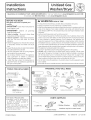
Installation
Instructions
--i@
Unitized Gas
Washer/Dryer
Questions on installation? Call: 1-800-GECARES (US}or Visit our Web site at: www.GEAppliunces.com (US).
In Canada, call 800-561-3344 or visit www.GEAppliunces.cu.
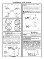
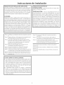
BEFOREYOU BEGIN
Readthese instructions completely and
carefully.
•IMPORTANT-Save these instructionsfor
localinspector'suse.
•IMPORTANT- Observe all governing
codesand ordinances.
• Note to Installer - Be sure to leave these
instructionswith thecustomer.
• Note to Customer - Keepthese instructions
with your Use and Care Book for future
reference.
• Beforethe appliance isremovedfrom service
or discarded, remove the washer and dryer
door.
•inspectthedryerexhaustoutlet andstraighten
theoutlet walls iftheyare bent.
• Service information and the wiring diagram
are locatedat theaccesspanel.
• Do not allow childrenon or in the appliance.
Close supervision of children is necessary
whentheapplianceisusednear children.
• Install the dryer where the temperature is
above50°F(].O°C)for satisfactoryoperationof
thedryercontrolsystem.
WARNING RISK OF FIRE
, Toreducetheriskofsevereinjuryordeath,followallinstallationinstructions.
. Applianceinstallationmustbeperformedbyaqualifiedinstaller.
. Installtheclothesapplianceaccordingtotheseinstructionsandinaccordancewithlocal
codes.Intheabsenceof localcodes,installationmustcomplywith NationalFuelGas
Code,ANSIZ223.1/NFPA54ortheCanadianNaturalGasandPropaneInstallationCode,
CSAB149,1,
,CalifomiaSafeOnnkingWaterandToxicEnforcementAct.
Thisact requiresthegovernorofCaliforniatopublisha listofsubstancesknowntothe
statetocausecancer,birthdefectsorotherreproductiveharmandrequiresbusinesses
to warn customersof potentialexposureto suchsubstances.Gasappliancescan
causeminorexposuretofourofthesesubstances,namelybenzene,carbonmonoxide,
formaldehydeandsoot,causedprimarilybytheincompletecombustionofnaturalgas
or LPfuels.Properlyadjusteddryerswillminimizeincompletecombustion.Exposureto
thesesubstancescanbeminimizedfurtherbyproperlyventingthedryertotheoutdoors.
, Thisappliancemustbeexhaustedtotheoutdoors.
, Useonly4"rigidmetalductingforexhaustingtheappliancetotheoutdoors.
, DONOTinstalla clothesdryerwithflexibleplasticductingmaterials.If flexiblemetal
(semi-rigidorfoiFtype)ductisinstalled,it mustbeULlistedandinstalledinaccordance
withtheinstructionsfoundin"ConnectingTheDryerToHouseVent"onpage8 ofthis
manual.Flexibleventingmaterialsareknowntocollapse,beeasilycrushed,andtraplint.
Theseconditionswillobstructdryerairflowandincreasetheriskoffire.
, Donotinstallorstorethisapplianceinanylocationwhereitcouldbeexposedtowater
andorweather.
, Savetheseinstructions.(Installers:Besuretoleavetheseinstructionswiththecustomer).
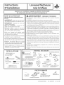
TOOLS YOU WILL NEED
{x2I
i0" ADJUSTABLEWRENCHES _._
8"PIPEWRENCH LEVEL
SUPJOINTPUERS FLATBLADESCREWDRIVER
1/4" Nutdriver
MATERIALS YOU WILL NEED
4'IDIA.METALDUCT
(RECOMMENDED) 4'IDIAMMETALELBOW
4"DIA.FLEXIBLEMETAL(SEMI-RIGID)
ULLISTEDTRANSITIONDUCT
(IFNEEDED)
KITWXO8XlO077(INCLUDES2ELBOWS)
4"DIA.FLEXIBLEMETAL(FOILTYPE)
ULLISTEDTRANSITIONDUCT
(IFNEEDED.)
EXHAUSTHOOD
(x2)
4"DUCTCLAMPS
OR
4"SPRINGCLAMPS
PIPE
COMPOUND SOAPSOLUTION
FORLEAKDETECTION
DUCTTAPE
FLEXIBLEGASLINECONNECTOR
SAFETYGLASSES
GLOVES
<5
4"COVERPLATE(IFNEEDED)
(KITWEIM454)
In the state of Massachusetts:
• Installation must be performed by
e qualifledor licensed contractor,
plumber, or gesfltter qualified or
licensed by the state.
• When using bell-type gas shut-off
valves, they shell be T-handle type.
• A flexible gas connector, when used,
must not exceed 3 feet.
1.Cable Tie
PARTS SUPPLIED
2 Washer Hoses
% O
2 Stainer Screens
2 Rubber Washers Rubber Washers
(washers may be in water hoses)
Printedinlexico 233D1835PO01 31-16655-6 12-12 GE

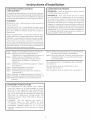
Installation
INSTALLATION REQUIREMENTS LOCATION
Thisappliance must beinstalled on firm flooring to minimize
vibration during spin cycle. Concrete flooring is best, but
wood base issufficient, provided floor support meets FHA
standards. This appliance should not be installed on rugs
or exposed to weather.
PLUMBING
WATERPRESSURE- Must be 20 psi minimum to 120 psi
maximum.
WATERTEIVlPERATURE- Household water heater should be
set to deliver water at 120° to 150°F (50° to 66°C)INTHE
WASHERwhen hot wash is selected.
SHUTOFFVALVES-Bothhot and cold shutoffvalves (faucets)
should be supplied.
DRAIN- Water may be drained into standpipe or set tub.
Discharge height MUSTNOT BE LESSTHAN 30 INCHES,
and no more than 6 feet above the base of the washer.
Standpipe must be 1-!/2 inches minimum inside diameter
and must be open to atmosphere.
nstructions
ELECTRICAL REQUIREMENTS
CAUTION: Beforeplugging in washer, read the following
electrical requirements.
CAUTION: Forpersonal safety, do not use anextension
cord or adapter plug with this appliance. Donot, under any
circumstances, cut or remove the third grounding prong
from the power cord. Follow national electrical codes and
ordinances. Thisappliance must besupplied with the voltage
and frequency indicated on the rating plate (located at the
top of the dryer front panel),and connected to an individual,
properly grounded branch circuit, protected by a 15- or 20-
amp circuit breaker or time-delay fuse. If the electric supply
provided does not meet the above requirements, call a
licensed electrician.
Step 1
Step 2
Step 3
Step 4
Step 5
Step 6
Step 7
Step 8
Step 9
Verify Your Gas Installation (seesection 2).
Prepare the Area and Exhaust for Installation of
appliance (seesection 1).
Check and Insure the Existing External Exhaust
is Clean (seesection 1)and Meets Attached
Installation Specifications (seesection 6).
Remove the Foam Shipping Pads(seesection 1).
Move the appliance to the Desired Location.
Levelyour appliance (seesection 8).
Connect the Gas Supply (seesection 3) and check
for leaks (seesection 4).
Connect the External Exhaust (seesection 7).
Connect to plumbing facilities (seesection 11).
Step 10 Connect the Power Supply (seesection 5).
Step 11 Check the Operation of the Power Supply,Gas
Connections, and Venting.
Step 12 Place the Owners Manual and the Installation
Instructions in a Location Where They Will Be
Noticed Bythe Owner.
For Alcove or Closet Installation see section 1:3.
For Bathroom or Bedroom Installation seesection 14.
For Mobile or Manufactured Home see section 12.
ADJUSTING FOR ELEVATION
. Gas clothes dryers input ratings are based on sea level
operation and need not be adjusted for operation at
or below 2000 ft. elevation. For operation at elevations
above 2000 ft., input ratings should be reduced at a rate
of 4 percent for each 1000 ft. above sea level.
. Installation must conform to local codes and ordinances
or, in their absence with the National Fuel Gas Code,
ANSI Z22:3.1/NFPA54, or the Natural Gas and Propane
Installation Code,CSAB149.1.
2

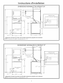
Installation Instructions
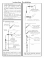
L5
51"
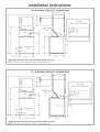
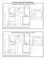
24" NOMINAL PRODUCT DIMENSIONS
_---'23.75"----_
W(]ter Inlets
(reor)
* Dimension represents door closed including handle and knobs.
NOTE:With feet set at mid position, feet can be adjusted +_.575".
Gas Inlet
(Rearview of appliance)
27" NOMINAL PRODUCT DIMENSIONS
F
52.9"
0oolo o O
_._ Drc]in outlet
i (rec]r)
_-- 3.9"
_--- 26.8"
--12.5"
]
36.5"
L
W(]ter Inlets
_------'26.7"-----_
_47"_
4.35"
_------ 30.85"------_
* Dimension represents door closed including handle and knobs.
NOTE:With feet set at mid position, feet can be adjusted +_.575".
Gas Inlet
(Rec]rview of appliance)
3

Installation Instructions
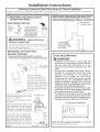
Minimum Clearance Other Than Alcove or Closet Installation
Minimum clearance to combustible surfaces and for air opening are: 0 in. clearance both sides and rear.Consideration
must be given to provide adequate clearance for installation and service.
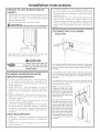
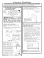
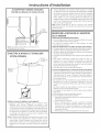
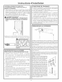
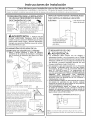
I-_ PREPARING FOR INSTALLATION
OF NEW APPLIANCE
DISCONNECTING GAS
TURNGAS
SHUT-OFFVALVEI_ DISCONNECTANDDISCARDOLD,_._,
TOTHEOFF ___ FLEXIBLEGASCONNECTORAND
POS,T,ON OLDTRANS,T,ONDUCT,NG
MATERIAL.REPLACEWITHNEW
CSA(AGA)APPROVEDFLEXIBLE
GASLINECONNECTORANDUL
APPROVEDTRANSITIONDUCT.
WARNING - NEVERREUSEOLD
FLE×IBLE CONN ECTORS.
Theuse of old flexible connectors can cause leaks and
personal injury. Always use new flexible connectors
when installing gas appliances.
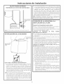
REMOVING LINT FROM WALL
EXHAUST OPENING
• Removeand discard existing plastic or metal foil
transition duct and replace with ULlisted transition duct.
_j WALL
INTERNAL_t_,].DUCT _ CHECKTHATEXHAUST
OPENING -'_-_ \ G "'.. HOODDAPIPEROPENS
ANDCLOSESFREELY.
TILTTHEAPPLIANCE
SIDEWAYSAND REMOVE
THE FOAMSHIPPINGPADS
BYPULLINGATTHESIDES
AND BREAKINGTHEMAWAY
FROMTHEAPPLIANCELEGS.
BESURETOREMOVEALL OF
THE FOAMPIECESAROUND
THE LEGS.
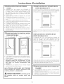
After the machine is in the home,
remove remaining packing material/
carton from washer.
DO NOT REMOVE SHIPPING ROD AT
THISTIME.
Removestyrofoam block. Removethe
bag containing theWasher hosesand
parts parts from tub. Put styrofoam
block back in tub opening to hold tub
in placeduring the rest of installation.
Hove washer close to final position.
Make sure there is at least a 24"
clearance on right side of washer to
remove shipping bar.PULLSHIPPING
BAROUT USINGYELLOWPLASTIC
HANDLE. Keep bar so it can be
reinstalled if washer is ever moved
again.
II
StyrofoamBlock
and Parts
Yellow
" Plastic
/ Handle
NEW HONE OR REMODELING FAUCETS/
DRAIN STANDPIPE/ELECTRICAL LOCATIO N
Right side of
Laundry Center
12"--_
_ .................. _|
Locate spigots, "
drain standpipe s3" |
and electrical plug |
!
in this area
!
FLOOR
I-_ GAS REQUIREMENTS
WARNING
, Installation must conform to local codes and
ordinances, or in their absence, with the National
Fuel Gas Code, ANSI Z223.1/NFPA 54, or the
Natural Gas and Propane Installation Code, CSA
B1491
. Thisgas dryerisequippedwitha Valve& Burner
Assembly foruse onlywith naturalgas Using
conversion kit WE25M73 for 24" Models or
WE25M74 for 27" Models,your localservice
organizationcan convertthisdryerforuse with
propane (LP)gas ALL CONVERSIONS MUST BE
MADE BY PROPERLY TRAINED AND QUALIFIED
PERSONNEL AND IN ACCORDANCE WITH LOCAL
CODES AND ORDINANCE REQUIREMENTS
• Theappliancemustbedisconnectedfromthegassupply
pipingsystemduringanypressuretestingofthatsystem
ata testpressureinexcessof05 PSI(34KPa)
• The appliancemustbe isolatedfromthegassupply
pipingsystembyclosingtheequipmentshutoffvalve
duringanypressuretestingofthegassupplypipingof
testpressureequaltoorlessthan05 PSI(34KPa)
27" GASSUPPLYCONNECTION
3"
Note: 24" Gas supply connection has a flexible
hose thus dimensions will vary.
4

Installation Instructions
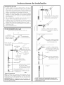
GAS SUPPLY
, A 1/8-in.National Pipe Taper thread plugged tapping,
accessible for test gauge connection, must be installed
immediately upstream of the gas supply connection to
the dryer, Contact your local gas utility should you have
questions on the installation of the plugged tapping.
. Supply line isto be 1/2-in. rigid pipe and equipped with
an accessible shut-off within 6 ft. of, and in the same
room with the dryer.
,Use pipe thread sealer compound or Teflon tape
appropriate for natural or LPgas.
, You must usewith this dryer a flexible metal connector
listed ANSI Z21.24 / CSA 6.10. The length of the
connector shall not exceed 3 ft.
, Connect flexible metal connector to dryer and gas
supply.
, Open shut-off valve.
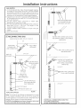
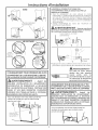
RECONNECTING GAS
Listed connector ANSI Z21.24 / CSA6.10
BACK OF
APPLIANCE
24"
NEW METAL _.. _ _k_>4/ '_
FLEXIBLEGAS
LINECONNECTOR
/
2a" & 27"
INLET FROM
APPLIANCE
FLARE
ADAPTOR
27" ONLY
NEW METAL
FLEXIBLE GAS
LINE CONNECTOR
ADAPTOR
/8" NPT INLET
FROM APPLIANCE
27"ONLY
ELBOW
27" ONLY
NPT PIPE PLUG
FOR CHECKING GAS
INLET PRESSURE
SHUT-OFF VALVE
AT LEAST 1/2"
FLOOR
ITEHS NOT SUPPLIED
Note: The connector and fittings are designed for use only
on the original installation and are not to be reused for
another appliance or at another location. Keepflare end of
adaptor free of grease, oil and thread sealant.
CAUTION: Use adopters as shown. Connector nuts must
not be connected directly to pipe threads.
27"
APPLYPIPECOMPOUND
TOTHEADAPTORAND
APPLIANCEGASINLET.
TIGHTENTHEFLEXIBLEGASLINETO
THEADAPTORUSING2 ADJUSTABLE
WRENCHES.
APPLY PIPE COMPOUND TO
APPLIANCE INLET
24"
;HTEN THE FLEXIBLE GAS
LINE TO THE APPLIANCE
INLET USING 2 ADJUSTABLE
WRENCHES.
24" & 27"
_ APPLY PIPECOMPOUND
TO ALL MALE THREADS
24" & 27"
5
TIGHTEN ALL CONNECTIONS USING TWO
ADJUSTABLE WRENCHES.
DO NOT OVERTORQUE GAS CONNECTIONS!

Installation Instructions
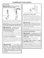
[-4]LEAK TEST
I WARNING: NEVER USE AN OPEN
FLAME TO TEST FOR GAS LEAKS.
OPEN
GASVALVE.
Check oil connections for leakswith soapy solution or equivalent.
Apply soap solution. Bubbles indicate leaks. Leak test solution
must not contain ammonia which could cause damage to the
brass fittings, tfleak are found, close valve retighten thejaint and
repeat the soap test.
[_ELECTRICAL CONNECTION INFORMATION
WARNING - TO REDUCE THE
RISK OF FIRE, ELECTRICAL SHOCK,
AND PERSONAL INJURY:
. DO NOT USEAN EXTENSIONCORDORAN ADAPTER
PLUGWITH THISAPPLIANCE.
Dryer must be electrically grounded in accordance
with local codes and ordinances, or in the absence
of local codes, in accordance with the NATIONAL
ELECTRICALCODE,ANSI/NFPANO.70.
ELECTRICAL REQUIREMENTS
This appliance must be supplied with 120V, 60Hz, and
connected to u properly grounded brunch circuit,
protected by u 15- or 20- amp circuit breaker or time-
delay fuse. If electrical supply provided does not meet the
above specifications, it is recommended that a licensed
electrician install an approved outlet.
, WARNING - THIS DRYER IS
EQUIPPED A THREE-PRONG (GROUNDING)
PLUG FOR 'fOUR PROTECTION AGAINST
SHOCK HAZARD AND SHOULD BE PLUGGED
DIRECTLY INTO A PROPERLY GROUNDED
THREE-PRONG RECEPTACLE. DO NOT CUT
OR REMOVE THE GROUNDING PRONG FROM
THIS PLUG.
ENSURE PROPERGROUND EXISTSBEFORE USE.
GROUNDING INSTRUCTIONS
This appliance must be grounded. In the event of
malfunction or breakdown, grounding will reduce the risk
of electric shock by providing u path of least resistance
of electric current. This appliance is equipped with a
cord having an equipment-grounding conductor and
a grounding plug. The plug must be plugged into an
appropriate outlet that isproperly installed and grounded
in accordance with all local codes and ordinances.
WARN IN G - Improper connectionofthe
equipment-grounding conductor can result in a risk
of electric shock. Check with a qualified electrician
or serviceman if you are in doubt as to whether the
appliance is properly grounded.
Do not modify the plug provided with the appliance. If it
will not fit the outlet, have a proper outlet installed by a
qualified electrician.
_-I EXHAUST INFORMATION
I WARNING - IN CANADA AND IN THE
UNITED STATES,THE REQUIRED EXHAUST DUCT
DIAMETER IS 4 IN (102ram). DO NOT USE DUCT
LONGER THAN SPECIFIED IN THE EXHAUST
LENGTH TABLE.
Using exhaust longer than specified length will:
• Increase the drying times and the energy cost.
Reducethe dryer life.
Accumulate lint, creating a potential fire hazard.
The correct exhaust installation is YOUR
RESPONSIBILITYoProblems due to incorrect installation
are not covered by the warranty.
Remove and discard existing plastic or metal foil
transition duct and replace with ULlisted transition duct.
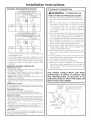
The MAXIMUMALLOWABLEduct length and number of
bends of the exhaust system depends upon the type of
duct, number of turns, the type of exhaust hood (wall
cap), and all conditions noted below. The maximum duct
length for rigid metal duct isshown in the table below.
6

Installation instructions
Use only for short
run installations
No. of 900 Rigid Rigid
Elbows Metal Metal
O 56 Feet 42 Feet
i 48 Feet 34 Feet
2 40 Feet 26 Feet
3 32 Feet 18 Feet
24" DRYEREXHAUSTLENGTH
RECOMMENDED MAXIMUM LENGTH
Exhaust Hood Types
Recommended Use only for short
run installations
No. of 900 Rigid Rigid
Elbows Metal Metal
O 45 Feet 56 Feet
i 53 Feet 26 Feet
2 24 Feet 16 Feet
EXHAUST INFORMATION (CONT.)
27" DRYEREXHAUSTLENGTH
RECOMMENDED MAXIMUM LENGTH
Exhaust Hood Types
Recommended
, For every extra 90° elbow, reduce the allowable vent
system length by 10ft.
, Two 45°elbows will be treated likeone 90°elbow. Forthe
sideexhaust installations,add one 90°elbow tothe chart.
, The total vent system length includes all the straight
portions and elbows of the system (transition duct
included).
EXHAUST SYSTEM CHECK LIST
HOOD ORWALL CAP
, Terminate in a manner to prevent back drafts or entry
of birds or other wildlife.
, Termination should present minimal resistance to
the exhaust air flow and should require little or no
maintenance to prevent clogging.
, Never install u screen in or over the exhaust duct. This
could cause lint build up.
, Wall cups must be installed at least 12 in.above ground
level or any other obstruction with the opening pointed
down.
SEPARATIONOFTURNS
For best performance, separate all turns by at least 4
ft. of straight duct, including distance between lust turn
and exhaust hood.
TURNS OTHERTHAN 90°
, One turn of 450 or less may be ignored.
, Two 450 turns should be treated us one 900 turn.
, Each turn over 450 should be treated as one 900 turn.
SEALINGOFJOINTS
, Alljoints should be tight to avoid leaks.The mule end of
each section of duct must point away from the dryer.
, Do not assemble the ductwork with fasteners that
extend into the duct. They will serve as a collection
point for lint.
, Duct joints can be made air and moisture-tight by
wrapping the overlapped joints with duct tape.
, Horizontal runs should slope down toward the outdoors
1/4 inch per foot
INSULATION
Duct work that runs through an unheated urea or is
near air conditioning should be insulated to reduce
condensation and lint build-up.
P-JEXHAUST CONNECTION
, WARNING - TO REDUCE THE
RISK OF FIRE OR PERSONAL INJURY:
, This apliancce must be exhausted to the outdoors.
, Use only 4" rigid metal ducting for the home exhaust
duct.
, Use only 4" rigid metal or UL-listed flexible metal
(semi-rigid or foil-type) duct to connect the dryer
to the home exhaust duct. It must be installed
in accordance with the instructions found in
"Connecting The Dryer To House Vent" on page 8 of
this manual.
, Donot terminate exhaust inu chimney, uwall, uceiling,
gas vent, crawl space, attic, under an enclosed floor,
or in any other concealed space of u building. The
accumulated lint could create a potential fire hazard.
, Never terminate the exhaust into a common duct
with u kitchen exhaust system. A combination of
grease and lint creates mpotential fire hazard.
, Do not use duct longer than specified in the exhaust
length table. Longer ducts can accumulate lint,
creating u potential fire hazard.
, Never install u screen in or over the exhaust duct. This
will cause lint to accumulate, creating mpotential fire
hazard.
, Do not assemble ductwork with any fasteners that
extend into the duct. Thesefasteners can accumulate
lint, creating mpotential fire hazard.
, Do not obstruct incoming or exhausted air.
, Provide an access for inspection and cleaning of
the exhaust system, especially at turns and joints.
Exhaust system shall be inspected and cleaned at
least once year.
THIS DRYER COMES READY FOR REAR
EXHAUSTING. IF SPACE IS LIMITED, USE
THE INSTRUCTIONS IN SECTION 9 TO
EXHAUST DIRECTLY FROM THE SIDES OR
BOTTOM OF THE CABINET.
EXTERNALDUCT
OPENING
CSA(AGA}APPROVED
NEWFLEXIBLEGAS For straight line installation, connect
LINECONNECTOR the drger exhaust to the external
exhaust hood using duct tape or
GAS clamp.
INLET
PIPE
DUCTTAPEOR
DUCTCLAMP
4" METALDUCTCUT
TO PROPERLENGTH
DUCTTAPEOR
DUCTCLAMP
7

Installation Instructions
STANDARD REAR EXHAUST
(Vented above floor level}
U
ECOMMENDED
ONFIGURATION
O MINIMIZE
XHAUSTBLOCKAGE
ELBOW HIGHLY
RECOMMENDED
2
NOTE: ELBOWS WILL PREVENT DUCT KINKING AND COLLAPSING
[8]LEVELING AND STABILIZING YOUR
APPLIANCE
_.__E LEVEL
-TO-SIDE
LEVEL
FRONT-TO-BACK.
2LEVELINGLEGS
Level and stabilizing your appliance
1. Carefully move the appliance to its final location.
Gently rock the appliance into position. It is important
not to damage the rubber leveling legs when moving
your appliance to its final location. Damage legs can
increase appliance vibration. It may be helpful to
spray window cleaner on the floor to help move your
appliance to its final position.
Note: do not usewasher cover to lift the unit.
2. To ensure the appliance is level and solid on all four
legs, tilt the appliance forward so the rear legs are off
the ground. Gently set the appliance back down to
allow the rear legs to self adjust.
3.With the appliance in its final position, place a level on
top of back part of the washer lid and check it side to
side, then check front to back. Screw the front leveling
legs up or down to ensure the appliance is resting solid
on all four legs (no rocking or the appliance should
exist), turn the lock nuts on each leg up toward the base
of the unit and snug with a wrench.
Note: Keep the leg extension at minimum to prevent
excessive vibration. The farther out legs are extended, the
more the unit will vibrate.
CONNECTING THE DRYER TO HOUSE
VENT
RIGIDMETALTRANSITIONDUCT
• Forbest drying performance,a rigid metaltransition duct is
recommended.
• Rigidmetal transitions ducts reducethe risk of crushing and
kinking.
UL-LISTEDFLEXIBLEMETAL(SEMI-RIGID)TRANSITIONDUCT
• tf rigidmetal ductcannot beused,thenUL-listedflexiblemetal
(semi-rigid)ductingcan beused(KitWX08X10077).
• Neverinstall flexible metal duct in walls, ceilings,floors or
otherenclosedspaces.
Formanyapplications,installingelbowsat boththedryer and
thewall ishighlyrecommended(seeillustrationson page 9).
Elbowsallowthe dryerto sitcloseto the wallwithout kinking
and or crushing the transition duct, maximizing drying
performance.
Avoidrestingthe duct on sharpobjects.
UL-LISTEDFLEXIBLEMETAL(FOIL-TYPE}TRANSITIONDUCT
• tn specialinstallations,it may be necessaryto connect the
dryerto the housevent usinga flexiblemetal (foiltype)duct.
AUL-listedflexiblemetal (foil-type)ductmay be usedONLYin
installations where rigid metal or flexible metal (semi-rigid)
ducting cannot be usedAND where a 4" diameter can be
maintained throughout the entire length of the transition
duct.
tn Canadaand the United States,onlythe flexiblemetal(foil-
type) ducts that comply with the "Outlinefor ClothesDryer
TransitionDuctSubject2158A"shallbeused.
Total length of flexible metal duct should not exceed 8 feet
(2.4m).
• Avoidrestingthe duct on sharpobjects.
• Forbestdryingperformance:
1.Slideoneendof theduct overtheclothesdryeroutlet pipe.
2.Securetheduct with a clamp.
3.Withthe dryerinits permanentposition,extendthe ductto
its full length.Allow 2"of duct to overlapthe exhaustpipe.
Cutoff and removeexcessduct. Keeptheduct asstraight
aspossiblefor maximumairflow.
/4.Securetheduct to the exhaustpipewith the otherclamp.
8

Installation instructions
DO
ELBOW HIGHLY
RECOMMENDED
USE
DO NOT _
EXCESSIVE
DON'T
I IIAPPLIANCE
I II°NFLEXIBLE
o
EXHAUST
[-_ 24" MODELS ONLY:
DRYER EXHAUST TO RIGHT, LEFT OR
BOTTOM CABINET
_WARNING - BEFOREPERFORMING
THIS EXHAUST INSTALLATION, BE SURE
TO DISCON NECTTH EAPPLIANCE FROM
ITS ELECTRICAL SUPPLY. PROTECT
YOUR HANDS AND ARMS FROM SHARP
EDGES WHEN WORKING INSIDE THE
CABINET. BE SURE TO WEAR GLOVES.
For downward venting, rotate elbow
sections so that elbow points downward
i
REMOVE
DESIRED
KNOCKOUT
(ONLY1)
JJ
!
FLO0
EXHAUST TO LEFT OR RIGHT SIDE OF
CABINET
, Forside ducting, remove the knockout (ONLY1).Rotate
elbow sections so that the opening points to the side.
Preassemble 4" elbow with 4" duct. Use only 4" UL
approved rigid metal for ducting inside the dryer.
, Insert duct assembly through the side opening and
connect to the internal elbow.
WARNING- Be sure not to pullor damage
the electrical wires inside the dryer when inserting the
duct.
4" ULapproved rigid metal
DUCT
TAPE
Apply duct tape as shown on the joint between the dryer
internal duct and the straight duct pipe.
WARNING-
Internal duct joints must be
R secured with tape, otherwise
they may separate and cause
a safety hazard.
27" MODELS ONLY:
DRYER EXHAUST TO RIGHT, LEFT OR
BOTTOM CABINET
WARNING -BEFOREPERFORMING
THIS EXHAUST INSTALLATION, BE SURE
TO DISCON NECTTH EAPPLIANCE FROM
ITS ELECTRICAL SUPPLY. PROTECT
YOUR HANDS AND ARMS FROM SHARP
EDGES WHEN WORKING INSIDE THE
CABINET. BE SURE TO WEAR GLOVES.
For downward venting, rotate elbow
sectionsm, so that elbow points downward.
9

Installation instructions
EXHAUST TO LEFT OR RIGHT SIDE OF
CABINET
, Rotate elbow sections so that the opening points to the
side to which you want to vent. Preassemble 4" elbow
with 4" duct, Use only 4" UL approved rigid metal for
ducting inside the dryer.
, Connect duct assembly to the internal elbow.
WARNING- Besure not to pull or damage the
electrical wires inside the dryer when inserting the duct.
, Apply duct tape as shown on the joint between the
dryer internal duct and the straight duct pipe.
WARNING-
Internal duct joints must be
H secured with tape, otherwise
they may separate and cause
a safety hazard.
PLUMBING INFORMATION WATER
[ -ISU PPL¥ REQUIREMENTS
, HOTAND COLD WATERFAUCETS- Must be within 42"
of the appliance water inlet hose connections. The
faucets must be 3/4" garden hose-type so inlet hoses
can be connected.
WATER PRESSURE- Must be between 10 and 120
pounds per square inch with a maximum unbalance
pressure, hot vs.cold flowing, of 10pounds per square
inch.
WATERTEMPERATURE- Water heater should be set to
deliver 140° to 150°F (60° to 66°C) in the washer when
HOTwash isselected.
, SHUT-OFFVALVES- Both hot and cold water shut-off
valves (faucets) should be supplied.
LOCATION- Do not install appliance in an area where
the temperature will fall below freezing. If appliance
is stored or transported in freezing temperatures, be
sure all water from the fill and drain systems has been
removed.
DRAIN REQUIREMENTS
, DRAINRATE- The drain or standpipe must be capable
of accepting a discharge at the rate of 16 gallons per
minute.
, DRAINHEIGHT- The drain height must be 33" minimum
and 96" maximum.
, STANDPIPEDIAMETER- The standpipe diameter must
be 1-1/2" minimum. There MUSTbe an air gap around
the drain hose in the standpipe. A snug fit can cause a
siphoning action.
SIPHON BREAKKIT - For a drain facility less than 33"
high, the hose, coupling and clamps provided in the
machine must be used and, in addition, a siphon break
MUST be installed on the back of the machine. Use
Siphon Break Kit WH/49X228 and follow instructions in
the kit.
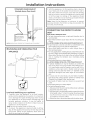
[ ]CONNECTING TO PLUMBING
FACILITIES
If not installed, install rubber washer in one end of hot water
hose. Thread hot water hose onto connection labeled H at
top rear of washer. Handtighten, plus an additional 1/8 turn
with pliers.
Ifnot installed, install rubber washer in one end of coldwater
hose. Thread cold water hoseonto connection labeled Cat
top rear of washer. Handtighten, plus an additional 1/8 turn
with pliers.
Moveappliance as closeto final location as possible,leaving
room for you to make water, drain, electrical and vent
connections to your home.
NOTE: If longer drain hose
is required, order drain hose
extension kit, GE part number
WH/49X301.Connectadditional
drain hose (contained in kit) to
original hose with hose clamp
(contained in kit).
Insertfreeendofdrain hoseinto
drain opening ofyour home up
to drain hose stopper (do not
removehosestopperitprevents
siphoning). If water valves and
drain are built into wall, fasten
drain hosetooneofwater hoses
with cable tie provided (ribbed
side on inside).If your drains is
a standpipe,fasten drain hose
to standpipe with cable tie
provided.
10

Installation instructions
_-2]MOBILE OR MANUFACTURED HOME
INSTALLATION
, Installation MUST conform to the MANUFACTURED
HOME CONSTRUCTION & SAFETY STANDARD,
TITLE 24, PART 32-80 or, when such standard is not
applicable, with AMERICAN NATIONAL STANDARD
FORMOBILE HOME,ANSi/NFPA NO. 501B.
, The appliance MUST be vented to the outdoors with
the termination securely fastened to the mobile home
structure.
, Thevent MUSTNOTbe terminated beneath a mobile or
manufactured home.
, Thevent duct material MUSTBEMETAL.
• KIT 14-D346-33 MUSTbe used to attach the appliance
securelyto the structure.
• Thevent MUSTNOTbeconnectedto anyother duct, vent,or
chimney.
, Do not use sheet metal screws or other fastening
devices which extend into the interior of the exhaust
vent.
• Providean opening with a freearea of at least 25 sq.in.for
introductionof outsideair intothedryer room.
ALCOVE OR CLOSET INSTALLATION
, If your appliance isapproved for installation in an alcove
or closet, it will be stated on a label on the appliance
back.
•Thedryer MUSTbevented to theoutdoors.Seethe EXHAUST
INFORMATIONsection.
Donot install this appliance with less than the minimum
clearances shown above.
Thecloset shouldbe vented to the outdoors to prevent gas
pocketingin caseofa gasleakinthe supplyline.
Nootherfuel-burningapplianceshallbeinstalledin thesame
closetwith the appliance.
CONSIDERATION MUST BE GIVEN TO PROVIDE
ADEQUATE CLEARANCES FOR INSTALLATION
AND SERVICE.
, WARNING: DO NOTINSTALLTHIS
APPLIANCE IN A CLOSET WITH A SOLID DOOR.
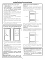
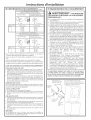
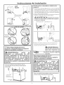
DOOR VENTILATION OPENING (27"
MODELS)
A minimum of 120 square inches of opening, equally
divided at top and bottom, is required. Air openings are
required to be unobstructed when a door is installed. A
Iouvered door with equivalent air openings for the full
length of the door is acceptable.
27" Model
z: :::n::
Sq.In.
Mli i o%.,n.
When louvers or registers are placed in door openings,
the free air openings of the louvers or registers must
equal 120 square inches.
DOOR VENTILATION OPENING (24"
MODELS)
A minimum of 72 square inches of opening isrequired. Air
openings are required to be unobstructed when a door is
installed. A Iouvered door with equivalent air openings for
the full length of the door is acceptable.
24" Model
/o/
H II J'ii'J;4 Sq. In.
I'l HT
When louvers or registers are placed in door openings,
the free air openings of the louvers or registers must
equal 72 square inches.
[Z4]BATHROOM OR BEDROOM INSTALLATION
, The appliance MUST be vented to the outdoors. See
EXHAUSTINFORMATIONsection 6 & 7.
, The installation must conform with local codes or,
in the absence of local codes, with the NATIONAL
ELECTRICALCODE,ANSI/NFPA NO. 70 and NATIONAL
FUELGASCODE,ANSIZ223.
11

Installation instructions
SERVICING
ILWARNING- LABEL ALL WIRES PRIOR TO DISCONNECTION WHEN SERVICING
CONTROLS. WIRING ERRORS CAN CAUSE IMPROPER AND DANGEROUS OPERATION
AFTER SERVICING/INSTALLATION.
Forreplacement parts and other information, refer to Owner's Manual for servicing phone numbers.
REGISTERYOUR NEW APPLIANCE TO RECEIVEANY
IIvlPORTANTPRODUCT NOTIFICATIONS.
Please go to www.GEAppliances.com or mail in your
Product Registration Card.
For questions on installation, call: 800.626.2000 (US)or
800-561-3344 (Canada).
12
Page is loading ...
Page is loading ...
Page is loading ...
Page is loading ...

Instructions d'Installation
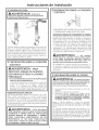
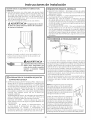
ALIMENTATION DE GAZ
. Un rouleau adh6sif pour branchement a gaz de 1/8 in.,
accessible pour des tests de calibrage du branchement,
doit _tre install6 immadiatement en amont du
branchement d'alimentation en gaz _ la s@cheuse.
Contactez I'entreprise de gaz la plus proche si vous avez
des questions sur I'installation du rouleau adh@sif pour
prise.
. Le branchement d'alimentation doit _tre un tuyau
rigide de 1/2in. et 6quip6 avec une valve de fermeture
accessible a 6 ft. de distance, et dans la m_me piece
que la s_cheuse.
Utilisez le compos6 pour tuyau ou le scotch Taflon
appropri_ pour le gaz naturel et LR
Vous devez utiliser avec cette s@cheuse un
branchement flexible en matal list6 comme
branchement ANSI Z21.24 / CSA6.!0. La Iongueur de
ce branchement ne devrait pas excader 3 ft.
Connectez le branchement flexible en matal 5 la
sacheuse et (3I'alimentation en gaz.
Ouvrez la valve de fermeture.
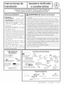
REBRANCHER LE GAZ
Branchement list6 ANSI Z2!.24 / CSA 6.10
24"
BRANCHEMENT
NEUF FLEXIBLE A,
GAZ EN METAL ENTREEA GAZ
DE LA SECHEUSE
/
RETOUR DE
L'APPAREIL
24" & 27"
FLARE
NPT ENTREE
DE L'APPAREIL 27"
SEULEMENT
45 ° COUDE
27" SEULEMENT
ADAPTATEUR
27" SEULEMENT
BRANCHEMENT NEUF
FLEXIBLE A GAZ EN
METAL
ADAPTATEUR
J NPT
1/8" POUR VERIFIER
LA PRESSION DU GAZ A
ENTRANT
VALVE DE FERMETURE
TAILLE DU BRANCHEMENT D'AU
MOINS 1/2"
PLANCHER
N'EST PAS FOURNI
Note: Le connecteur et les raccords sont congus pour 6tre
utilisas uniquement sur I'installation d'origine et ne doivent
pas 6tre rautilisas pour un autre appareil ou a un autre endroit.
Gardez fusae fin de I'adaptateur sans graisse, huile et un produit
d'6tanch6it6.
ATTENTION:Utiliser des adaptateurs, comme i!lustr@. Ecrous
connecteur dolt ne pas 6tre connect6 directement (]filetages.
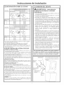
27"
APPLIQUEZLECOMPOSED'
ETANCHEtTEDESTUYAUTERIESA
L'ADAPTATEURETLEENTREEDUGAZ
DELA SECHEUSE
SERRERLA LIGNE DE BRANCHEMENT A
GAZ FLEXIBLE A L'ENTREEA GAZDE LA
SECHEUSE EN UTILISANT 2 CLES/_MOLETTE
24"
/_ APPLIQUEZ LECOMPOSE
D' ETANCHEITE DES
TUYAUTERIES A L' ENTREEA
GAZ DE LA SECHEUSE
24"
SERRERLA LIGNE DE
BRANCHEMENT A GAZ
FLEXIBLE A L'ENTREE A GAZ DE
LA SECHEUSE EN UTILISANT 2
CLES/_ MOLETTE
24" & 27"
APPLIQUEZ LE
COMPOSED' ETANCHEITE
DESTUYAUTERIES
SURTOUS LES FILETS
DESPARTIESM/_LE
24" & 27"
SERRER TOUS LES CONNECTEURS EN UTILISANT
2 CLt]S A MOLETTE. NE PAS SUR-SERREZ PAS LES
CONNECTEURS DE GAZ.
5
Page is loading ...
Page is loading ...
Page is loading ...
Page is loading ...
Page is loading ...
Page is loading ...

Instructions d'Installation
i_-IREPARATION
AVERTISSEMENT - MARQUEZ TOUSLES FILS AVANT LE DEBRANCHEMENT
LORSQUE VOUS EFFECTUEZ UN CONTROLE POUR REPARATION. LES ERREURS DE
BRANCHEMENT PEUVENT CAUSEES DES PROBLEMES DE FONCTIONEMENT APRES
REPARATION ET D'INSTALLATION.
Pour les pisces de rech(]nge et (]utres inform(]tions, veuillez reporter (]u Manuel de I'Utilis(]teur pour les num6ros de
t616phone du service (]prOsvente.
ENREGISTREZVOTRE NOUVEL APPAREIL POUR q)UE
VOUS RECEVIEZ DESINFORMATIONS IMPORTANTES
SUR LE PRODUIT.
Allez, SVP,sur notre site www.GffAppliances.com ou
envoyez par la poste votre Carte d'inscription du produit.
Pour des questions sur I'inst(]ll(]tion, composez:
800.626.2000 (E.U.)ou 800.56!.334/4 (CGnGdG)
12
Page is loading ...
Page is loading ...
Page is loading ...
Page is loading ...
Page is loading ...
Page is loading ...
Page is loading ...
Page is loading ...
Page is loading ...
Page is loading ...
Page is loading ...
Page is loading ...
-
 1
1
-
 2
2
-
 3
3
-
 4
4
-
 5
5
-
 6
6
-
 7
7
-
 8
8
-
 9
9
-
 10
10
-
 11
11
-
 12
12
-
 13
13
-
 14
14
-
 15
15
-
 16
16
-
 17
17
-
 18
18
-
 19
19
-
 20
20
-
 21
21
-
 22
22
-
 23
23
-
 24
24
-
 25
25
-
 26
26
-
 27
27
-
 28
28
-
 29
29
-
 30
30
-
 31
31
-
 32
32
-
 33
33
-
 34
34
-
 35
35
-
 36
36


Kenmore GUD24GSSJ0WW Installation guide
- Category
- Washing machines
- Type
- Installation guide
Ask a question and I''ll find the answer in the document
Finding information in a document is now easier with AI
in other languages
Related papers
Other documents
-
GE GUD27ESSJ1WW Installation guide
-
-
Whirlpool YLTE5243DQB Installation guide
-
-
-
GE WSM2780HWW User manual
-
-
-
Maytag YMET3800TW0 Installation guide
-
Hotpoint DBLR333EE1WW Installation guide