Page is loading ...

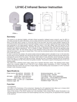
Summary
Specifications
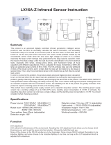
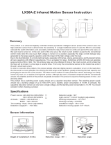
LX-PR-65S-Z Infrared Sensor Instruction
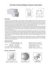
123mm
76mm
100mm
Detection range 22
10m
Detection angle
110°
Sensor information
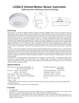
This product is an advanced digitally controlled infrared pyroelectric intelligent sensor product.This product uses one
high-resolution sensor that is almost twice the sensitivity of a single traditional sensor.It uses the MCU to accurately
calculate the switch information, and accurately controls the relay to be turned on at the zero point of the sine wave, so
that each load is turned on. At the zero point of the sine wave, the inrush current problem caused by the conventional
control mode when the sine wave high voltage is turned on is avoided, especially the large current damage relay
generated by the large-capacity capacitor under the impact of the high voltage under the load.
Due to the diversification of current electrical loads, especially LED lamps, energy-saving lamps, and fluorescent lamps
all have capacitors with different capacitances. This is a disaster for relays. Sometimes a 50W LED lamp can generate
surge currents of 80 to 120A. The 10A ordinary relay can only withstand 3 times of the inrush current, and it is likely that
the relay will be broken in a few days or several times. This is why the conventional sensor on the market has a short
life and a small load current.
In order to overcome this problem, this product adopts advanced digital precision calculation to turn on the load when
the sine wave is at zero potential, thus solving the load surge current problem, greatly enhancing the load capacity and
prolonging the service life of the product. The latest control method of mass production sensor technology can easily
control any load. It is a medium and high-end product. Although the cost is increased compared with the conventional
version, the reliability and life of the product are greatly increased. This product is equal to choosing peace of mind, and
choosing safety.
This product has a switching power supply version and a capacitor step-down version. The switching power supply
version has a working voltage of up to 100V-277V and a standby power consumption of <0.5W. In principle, the
capacitive step-down version can only have a single voltage, and the standby power consumption is >0.7W. You should
consider it when choosing a product.
Power source: 220-240VAC,50Hz/60Hz
100-130VAC,50Hz/60Hz
All loads 1200W 220-240VAC
800W 100-130VAC
Detection angle: 110º(adjustable)
Time setting: 10sec-12min (adjustable)
Detection range(22°C):
10m Max.
Working temperature: -10°C-+40°C
Working humidity: <93%RH
Light-control: 10LUX-2000LUX (adjustable)
Installation height: 1.8-2.5m
Detection motion speed: 0.6-1.5m/s

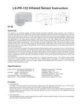
Adjust time setting of load work. Turn clockwise to increase it and turn anti-clockwise to
decrease it. The time setting is about 12min when turn to max, and the time setting is
about 10sec when turn to min .
10sec~12min
(1)Time setting
NOTE:When the light be auto off,it will take 4 second before the sensor is ready to detect
another movement,that is,only signal detected 4 seconds later can the light be auto-on.
It is mainly for the adjustment of the delay time from the moment the signal detected and light
auto-on till the light auto-off. You can define the delay time to your practical need. But you’d
better lower the delay time for the sake of energy saving, since the microwave sensor has the
function of continuous sensing, that is, any movement detected before the delay time
elapses will re-start the timer and the light will keep on only if there is human in the detection
range.
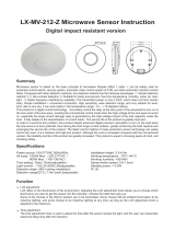
Knob adjustment
1. TIME adjuster: adjust the light delay
2. LUX adjuster: adjust level of light operation
TIME
Night Operation Day Operation
LUXTIME
-+
10sec~12min
Connection-wire diagram
L——brown
N——blue
L——red
Connect L and N with power
Connect L and N with load.
Sensor
Brown
Blue N
L
Load
LRed
Input
Output
LUX adjustment:
LUX refers to the illuminance of the environment. Adjusting the LUX adjustment knob allows you to choose which
illuminance you want to get the sensor into the induction. Choose the habit that suits you.
Some of the choices in the 20LUX solution are to be illuminated. Some choose 50LUX ambient illumination to be
inductive lighting, and some choose to be inductive lighting at any time, as long as the LUX adjustment knob is
adjusted to the maximum.
Function
Time adjustment:
The time adjustment knob is used to adjust the time after the sensor senses the light, and the user can reasonably
select the delay time after the induction.

1. Turn LUX knob clockwise to the maximum (SUN). Turn time knob anti-clockwise to the minimum.Turn
sensor knob clockwise to the maximum.
2. Power connected, the load controlled will start working and stop working 2±1 seconds later when there is
no continual signal detected.
3. Once detected, the load works and the indicator on and stops working 10 seconds later when there is no
continual signal detected.And if signal detected 4 seconds later, the load should start working and the
indicator on and stop working 10 seconds later when there is no continual signal detected.
4. Turns LUX knob anti-clockwise to the minimum. If it is tested under the circumstance above 10LUX, load
should not work after induction load stop working; but if you cover the detection window with opaque objects
(towel etc), the load works. Under the condition of no induction signals, the load should stop working within
10 sec.
Test
The load don’t work:
a. Please check the power and load connect is correct.
b. Check if the load is good.
c. Check if the show lamp accelerates its speed after detecting.
d. Check if the working light corresponds to the light-control.
The sensitivity is poor:
a. Please check if there is hinder in front of the detection window to effect receiving the signals.
b. Please check if the ambient temperature is too high.
c. Please check if the signals source is in the detection fields.
d. Please check if the installation height corresponds to the height showed in the instruction.
e. Please check if the moving orientation is correct.
The sensor can’t shut the load automatically:
a. Check if there are continual signals in the detection fields.
b. Check if the time setting is set to the longest.
c. Check if the power corresponds to the instruction.
d. Check if the temperature change obviously nears the sensor, such as air condition or central heating etc.
Avoid installing it near air temperature alteration zones such as air condition, central heating, etc.
Considering your safety, please don’t open the cover when you find the hitch after installation.
If there is difference between product and instruction, please refer to product mainly.
Some problem and solved way
Should be installed by electrician or experienced man.
Avoid installing it on the unrest objects.
There shouldn’t be hindrance and moving object in front of the detection window effecting detection.
Note
Adjust working light. Turn clockwise to increase it and turn anti-clockwise to decrease it.
When turn to mini, it will only work below the light-control about 10LUX, when turn to
max, it can work any light-control.
<10-2000LUX
(2)Light-control setting

Warning!
● Please confirm with prefessional installation.
● Please cut off power supply before installation and removal operations.
● Make sure that you have cut off the power for safety purposes.
● Improper operation caused losses, the manufacturer does not undertake any responsibility.
This manual is for the current content programming of this product, there are any changes
and modifications to the manufacturer without notice!
This instruction, without our permission, should not be copied for any other purposes.
/