Page is loading ...

Page 1Rev. 031020 1-888-651-3431
Motorcycle Wheel Chock
Instructions for
Part # BW-PRO-CHOCK
General Guidelines
• It is the user’s responsibility to read and follow all instructions.
• Keep these instructions with the product at all times and review before each use.
• It is the responsibility of this product’s owner to furnish the instructions to any person that borrows
or purchases the product.
• Inspect the product before use to ensure it is assembled properly and all parts are in safe working
order and free of defects.
• Never modify this product in any way.
• Fits tires from 15" - 22".
• All circumstances cannot be addressed in these instructions. Please use common sense and
practice general safety measures when using this product.
• Parts and/or instructions are subject to change without notice.
Part Description Quantity
A Base 1
B Vertical Arm 1
C Leg 2
D Wheel Cradle 1
E Wheel Stop 1
F Arm Bracket 1
Part Description Quantity
G Cradle Bracket 1
H M12x35 Turn Knob 2
I Pin with Clip 4
J M8x40 Socket Head Bolt 2
K M8 Fender Washer 2
L M8 Nut 2
A B C
D E F G
H I J K L
Parts
Tools Needed: 5mm hex key, 13mm wrench

Page 2Rev. 031020 1-888-651-3431
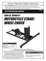
Assembly
Step 1. Slide the two legs (C) into the slots on the base (A). Each leg ts into its own slot, facing op-
posite directions so they can extend or contract as needed. Fit the turn knobs (H) into the top holes to
secure the legs at the proper distance. The distance can be adjusted to t a truck bed or trailer once
the chock is assembled.
Step 2. Fit the vertical arm (B) into
the base (A). Secure with a pin and
clip (I).
Step 3. Fit the arm bracket (F) onto
the vertical arm (B). Secure the
bracket at the appropriate height
with a pin and clip (I).
Step 4. Attach the wheel stop (E)
to the arm bracket (F) using a pin
and clip (I).
(1a)
(2a)
(3a)
(4a)
(2b)
(3b)
(4b)
(1b) (1c)

Page 3Rev. 031020 1-888-651-3431
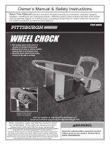
Step 5. Attach the cradle bracket (G) to the base (A) using the bolts (J), washers (K), and nuts (L).
Secure with a 5mm hex key and 13mm wrench.
Remove one leg from the inside of one chock. Remove the end cap of the inside leg of the other
chock. Make sure the slot for the removed leg and the other inside leg line up. Fit the leg into the slots
of both chocks, connecting them. Adjust and tighten as needed.
Step 6. Attach the wheel cradle (D) to the cradle bracket (G). Secure the cradle at the appropriate
position with a pin and clip (I).
(5a)
(6a) (6b)
(5b) Underside (5c)
Two-Chock Option

Page 4Rev. 031020 1-888-651-3431
Product Warranty and Liability
GENERAL PRODUCT WARRANTY: Products purchased from the Authorized Dealer (original place of purchase) or Merchant (“Dealer”)
will be free of defects in material and workmanship at the time of receipt, and will meet the specications stated at the place of pur-
chase transaction or online at the Dealer’s website, under normal use and service when correctly installed, operated and maintained.
This product warranty is eective for the period of time stated below, unless otherwise stated in the product instructions or depicted in
the product advertisement. All Authorized Dealer warranties are NON-TRANSFERABLE and cover only the original end purchaser. This
limited warranty does not cover products purchased through non-authorized dealers. Non-authorized dealer receipts are not accepted
for warranty verication.
***Warranty claims must be made directly to the original place of purchase.***
WARRANTY PERIOD: This warranty remains in force for one year from the date of the product’s accepted delivery. The Authorized
Dealer oers a one year manufacturer’s warranty for most products unless otherwise specied on the product advertisement.
WARRANTY SERVICE: The Authorized Dealer will replace any defective or malfunctioning part at no charge, including payment of the
shipping costs of parts or replacement product to and from the manufacturer. The purchaser is responsible for labor charges. If the
product does not meet specications as depicted in the advertisement, the Authorized Dealer will refund the full purchase price of the
product.
Questions regarding the warranty on a specic product and warranty claims should be directed to the Authorized Dealer with whom the
purchase transaction was made.
WARRANTY LIMITATIONS: The above warranty does not apply to products that are repaired, modied or altered by any party other
than the Authorized Dealer; are subjected to unusual physical stress or conditions (such as overloaded ramps or corrosion), natural
disaster, governmental actions, wars, strikes, labor disputes, riots, theft, vandalism, terrorism or any reason beyond reasonable control;
are damaged due to improper installation, misuse, abuse, accident or negligence in use, storage, transportation or handling, or tamper-
ing; or to products that are considered consumable items or items requiring repair or replacement due to normal wear and tear.
Product should be inspected prior to signing for delivery. Product damage incurred during shipping, unless noted on the Bill of Lading at
the time of delivery, renders this warranty void.
LIMITED LIABILITY: In no event shall THE AUTHORIZED DEALER be liable to the purchaser or any third party for any indirect, inciden-
tal, consequential, special, exemplary or punitive damages arising out of the use of the product, including, without limitation, property
damage, loss of value of the product or any third party products that are used in or with the product, or loss of use of the product or any
third party products that are used in or with the product.
Place the assembled chock in the trailer or truck bed. Fully extend the legs to t against the walls, then secure them
in place by tightening the turn knobs. Make sure the chock is stable and secure with cradle tilted forward before use.
The wheel cradle and wheel stop can be adjusted to t tires between 15" - 22". Adjustments will depend on the tire
width and style. When properly in place, the tire should be set in the wheel cradle even with or just above the chock
base. Always properly tie down your motorcycle before transport.
Installation
/