Page is loading ...

For maximum effectiveness and safety,
please read these instructions completely
before proceeding with installation.
Failure to read these instructions can result in an
incorrect installation.
MN-1081 • (021901) • ECR 9227
INSTALLATION GUIDE
Kit 60828HD
RAM 1500
Air Lift 1000 HD


TABLE OF CONTENTS
Introduction .......................................2
Notation Explanation ................................................2
Installing the Air Lift 1000 HD Kit ......................3
Hardware List .....................................................3
Tools List .........................................................3
Getting Started ....................................................3
Installing the Air Springs .............................5
Installing the Air Lines. . . . . . . . . . . . . . . . . . . . . . . . . . . . . . . 6
Before Operating ...................................8
Installation Checklist ................................................8
Maintenance and Use Guidelines ......................................8
Minimum and Maximum Air Pressure ...................................8
Limited Warranty and Return Policy ....................................8

2
MN-1081
Air Lift 1000 HD
Introduction
The purpose of this publication is to assist with the installation and maintenance of the
Air Lift 1000 HD air spring kit.
It is important to read and understand the entire installation guide before beginning
installation or performing any maintenance, service or repair. The information here
includes a hardware list, tools list, step-by-step installation information, maintenance
guidelines and a checklist for after completing the installation.
Air Lift Company reserves the right to make changes and improvements to its products
and publications at any time. Contact Air Lift Company at (800) 248-0892 or go online at
www.airliftcompany.com for the latest version of this manual.
NOTATION EXPLANATION
Hazard notations appear in various locations in this publication. Information which is
highlighted by one of these notations must be observed to help minimize risk of personal
injury or possible improper installation which may render the vehicle unsafe. The following
definitions explain the use of these notations as they appear throughout this guide.
INDICATES IMMEDIATE HAZARDS WHICH WILL RESULT IN SEVERE PERSONAL INJURY
OR DEATH.
INDICATES HAZARDS OR UNSAFE PRACTICES WHICH COULD RESULT IN SEVERE
PERSONAL INJURY OR DEATH.
INDICATES HAZARDS OR UNSAFE PRACTICES WHICH COULD RESULT IN DAMAGE TO
THE MACHINE OR MINOR PERSONAL INJURY.
DANGER
CAUTION
WARNING

3
MN-1081
Air Lift 1000 HD
Item Part # Description ............................................... Qty
A 48178 Air spring ............................................................... 2
B 09128 Air spring protector ............................................... 2
C 20937 Air line .................................................................15 ft
D 10466 Zip ties .................................................................. 6
E 21230 Valve cap ............................................................... 2
F 21233 5/16” Hex nut ........................................................ 4
G 21234 Rubber washer ...................................................... 2
H 18411 Star washer ........................................................... 2
I 18501 M8 Flat washer ..................................................... 2
J 21236 Tee fitting............................................................... 1
K 21455 Schrader valve ...................................................... 2
L 10638 Air line clamp ........................................................ 6
M 21730 Straight pump connector ...................................... 2
HARDWARE LIST TOOLS LIST
Description ...................................................... Qty
Standard and metric open-end/box wrenches ..........SET
Adjustable wrench .......................................................... 1
China or tire marker (white crayon) ................................ 1
Ratchet ........................................................................... 1
Pliers ............................................................................... 1
Standard & metric, regular & deep-well sockets ........ SET
5/16” drill bit (very sharp) ............................................... 1
Heavy-duty drill .............................................................. 1
Hose cutter, razor blade, or sharp knife ......................... 1
Hoist or Jack .................................................................. 1
Safety stands .................................................................. 2
Safety glasses ................................................................ 1
Air compressor or compressed air source ..................... 1
Spray bottle with dish soap/water solution .................... 1
Installing the Air Lift 1000 HD Kit
Missing or damaged parts? Call Air Lift customer
service at (800) 248-0892 for a replacement part.
STOP!
GETTING STARTED
1. Mark the upper and lower springs and spring seats with a china marker, tire marker
or white crayon to note its location (Fig. 1).
2. Remove the lower shock bolts from both shocks (Fig. 2).
g. 1
Mark spring
location in
reference to
upper and
lower spring
seat. Sample
of driver’s
(left) side
shown.
g. 2

4
MN-1081
Air Lift 1000 HD
3. Remove the brake line holder bolt from the Panhard (lateral bar) bracket behind the
passenger’s (right) side coil spring and pull line holder away from the bracket (Fig. 3).
Save the bolt for re-use.
4. Lift the vehicle up and support the frame with safety stands. Leave enough room to
drop the axle down low enough to remove the coil springs (Fig. 4).
5. Drop the axle down low enough so coil springs can be removed (axle hanging).
Remove one spring at a time for installing the air springs. If necessary, pull down on
the wheel or axle to create enough room for the springs to be removed.
6. With the spring removed, remove and discard the spring rubber isolator off the
middle of the coil spring (Fig. 5).
The rubber isolator at the top does not have to be removed.
g. 3
Remove
brake line
bolt and pull
line holder
away from the
bracket.
g. 4
g. 5
Leave top rubber
isolator on
spring.
Remove lower
rubber isolator
on the middle of
the spring.
NOTE

5
MN-1081
Air Lift 1000 HD
1. Cut the air line (C) in two equal lengths and install the straight pump connector (M)
and air line clamp (L) on one end of each air line. Remove the valve cap off the air
spring and screw the pump connector on the stem finger tight. Slide an air spring
protector (B) over each hose and onto the top of the air spring (A) (Fig. 6).
DO NOT USE ANY TOOLS TO TIGHTEN THE PUMP CONNECTOR OR DAMAGE TO
STEM WILL OCCUR.
2. Insert the air spring assembly into the top of the stock coil spring and push to the
bottom. Set the rubber upper spring seat on top of the spring assembly (if it fell out
of the upper spring seat when removing the coil spring) making sure the end of the
coil spring is positioned correctly in the mount (the end of the coil spring indexes into
the mount only one way).
There are small tabs on the rubber upper spring seat mount that go into holes in the upper
spring seat (Fig. 7).
NOTE
g. 6
A
B
C
L
M
g. 7
When installing
spring assembly,
make sure tabs
insert back into
the upper spring
seat holes that
align with them.
Installing the Air Springs
CAUTION

6
MN-1081
Air Lift 1000 HD
3. Insert the hose through the hole in the upper spring seat mount and reinstall the coil/air
spring assembly, making sure the mark (previously made in step one of getting started)
on the upper and lower portion of the coil spring aligns with the mark on the upper
and lower spring seats (Fig. 8). Slightly raise the axle up enough to seat the coil spring
into the upper and lower mounts and, as stated above, make sure the small tabs go
into the upper spring seat (Fig. 7). With the upper and lower spring seated, push the
protector up inside the upper rubber spring seat as far as possible. Repeat assembly
for the other side.
4. With both springs in position, raise the axle fully and reattach the lower shock bolts
(Fig. 2). Torque the lower shock bolts to 100 lb.-ft. (135Nm). Re-attach the passenger’s
(right) side brake line bracket and bolt previously removed and tighten securely (Fig. 3).
Remove the safety stands.
5. Using the zip ties (D) route the air lines above the frame and to the area back behind
the rear license plate. Above the coil springs, leave enough slack in the air lines for
suspension articulation.
A single-path air line installation is recommended for vehicles that typically have even weight
distribution (Fig. 9). If weight in the vehicle varies from side to side and unequal pressures
are needed to level the load, use a dual-path installation. For dual-path air line installations,
eliminate the tee fitting (J) and route separate air lines for both air springs (Fig. 10).
TO PREVENT THE AIR LINE FROM MELTING, MAINTAIN AT LEAST 6” (152MM) FROM
THE EXHAUST SYSTEM TO THE AIR LINE.
Installing the Air Lines
Single-path Air Line Routing
Dual-path Air Line Routing
g. 9 g. 10
g. 8
Align the marks
when installing
the spring
assemblies
CAUTION

7
MN-1081
Air Lift 1000 HD
1. If installing a single-path air line, choose a location for the tee fitting (J) on the wheel
well, license plate, or rear bumper. Determine and cut adequate length of air line (C)
to reach to the tee from left and right side air springs.
LEAVE SUFFICIENT AIR LINE SLACK TO PREVENT ANY STRAIN ON THE FITTING
DURING AXLE MOTIONS.
2. Use this procedure (Fig. 11) for all air line connections:
a. Slide the air line clamp (L) onto the air line (C).
b. Push the air line and air line clamp over the barbed stem so that the air line
covers all the barbs.
c. Compress the ears on the air line clamp with pliers and slide it forward to fully
cover the barbs.
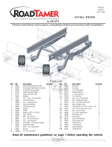
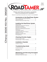
3. Select a location for the Schrader valve (K), ensuring that the valve will be protected
and accessible with an air hose (Fig. 12). Determine and cut adequate length of air
line (C) to reach from the tee to the Schrader valve or from the air springs to the
valve if using a dual-path installation.
4. Drill a 5/16” (8mm) hole for the Schrader valve (K) and mount as shown (Fig. 13).
Install the air line on the Schrader valve first. The rubber washer (G) serves as an
outside weather seal.
DO NOT INFLATE THE AIR SPRINGS BEFORE READING THE MAINTENANCE AND USE
GUIDELINES IN THIS INSTALLATION GUIDE AS WELL AS THE USER GUIDE INCLUDED
WITH THIS KIT.
Hex nut (F)
Schrader
valve (K)
Vehicle
body
or bumper
Flat
washer (I)
Star washer (H)
Rubber washer (G)
Nylon
air line (C)
Air line
clamp (L)
Drill 5/16”
(8mm) hole
Hex
nut (F)
Valve
cap (E)
g. 13
Installing the Air Lines
g. 11
From the
left
air spring
From the
right
air spring
To Schrader
valve
g. 12
A. Inside fuel tank filler door C. License plate or
B. Inside rear wheel wells rear bumper area
MICHIGAN
XXX-XXX
www.MICHIGAN.gov
A.
B.
C.
CAUTION
CAUTION

8
MN-1081
Air Lift 1000 HD
Before Operating
Clearance test — Inflate the air springs to 25-35 PSI (1.7-2.4BAR) and make sure
there is at least 1/2” (13mm) clearance from anything that might rub against each air
spring.
Leak test before road test — Inflate the air springs to 25-35 PSI (1.7-2.4BAR) and
use a soapy water solution to check all connections for leaks. All leaks must be
eliminated before the vehicle is road tested.
Heat test — Be sure there is sufficient clearance from heat sources, at least 6”
(152mm) for air springs and air lines. If a heat shield was included in the kit, install it.
If there is no heat shield, but one is required, call Air Lift customer service at
(800) 248-0892.
Road test — The vehicle should be road tested after the preceding tests. Inflate the
air springs so that the vehicle is level. Drive the vehicle 10 miles (16km) and recheck
for clearance, loose fasteners and air leaks.
Operating instructions — If professionally installed, the installer should review the
User Guide with the owner. Be sure to provide the owner with all of the paperwork
that came with the kit.
INSTALLATION CHECKLIST
Consult the included User Guide for information about fixing air leaks along with more
tips for maintenance and use before using the product.
MAINTENANCE AND USE GUIDELINES
1. Check air pressure weekly.
2. Always maintain normal ride height. Never inflate beyond 50 PSI (3.5BAR).
3. If the system develops an air leak, use a soapy water solution to check all air line
connections and the inflation valve core before deflating and removing the air spring.
FOR SAFETY AND TO PREVENT POSSIBLE DAMAGE TO THE VEHICLE, DO NOT EXCEED
MAXIMUM GROSS VEHICLE WEIGHT RATING (GVWR) OR PAYLOAD RATING, AS
INDICATED BY THE VEHICLE MANUFACTURER.
ALTHOUGH THE AIR SPRINGS ARE RATED AT A MAXIMUM INFLATION PRESSURE OF
50 PSI (3.5BAR), THE AIR PRESSURE ACTUALLY NEEDED IS DEPENDENT ON LOAD AND
GROSS VEHICLE WEIGHT RATING.
LIMITED WARRANTY AND RETURN POLICY
Air Lift Company provides a limited lifetime warranty to the original purchaser of its load support
products, that the products will be free from defects in workmanship and materials when used
on cars and trucks as specified by Air Lift Company and under normal operating conditions,
subject to the requirements and exclusions set forth in the full Limited Warranty and Return
Policy that is available at www.airliftcompany.com/warranty.
For additional warranty information contact Air Lift Company customer service.
Maximum Air PressureMinimum Recommended Pressure
50 PSI (3.5BAR)5 PSI (.34BAR)
CAUTION
CAUTION

9
MN-1081
Air Lift 1000 HD
Notes

Air Lift Company • 2727 Snow Road • Lansing, MI 48917 or PO Box 80167 • Lansing, MI 48908-0167
Toll Free (800) 248-0892 • Local (517) 322-2144 • Fax (517) 322-0240 • www.airliftcompany.com
Thank you for purchasing Air Lift products — the professional installer’s choice!
Need Help?
Contact our customer service department by calling
(800) 248-0892. For calls from outside the USA or
Canada, our local number is (517) 322-2144.
Register your warranty online at
www.airliftcompany.com/warranty
Printed in the USA
JJC-1018
California: WARNING: Cancer and Reproductive Harm – www.P65Warnings.ca.gov
/