Page is loading ...

Servimat M/L
09.04.2019
Pressure maintenance with degassing
GB
Operating manual
Original operating manual

Contents
2 — English
Servimat M/L — 28.01.2021
English
Servimat M/L
11.11.2019
Contents
1 Notes on the operating manual ............................................ 3
2 Liability and guarantee .......................................................... 3
3 Safety ........................................................................................ 3
3.1 Explanation of symbols .............................................................. 3
3.2 Personnel requirements ............................................................ 3
3.3 Personal protective equipment ................................................ 3
3.4 Intended use ................................................................................ 3
3.5 Inadmissible operating conditions .......................................... 4
3.6 Residual risks................................................................................ 4
4 Description of the device ....................................................... 4
4.1 Description ................................................................................... 4
4.2 Overview ....................................................................................... 4
4.3 Identification ............................................................................... 4
4.3.1 Type code ............................................................................ 5
4.4 Function ........................................................................................ 5
4.5 Scope of delivery ......................................................................... 6
4.6 Optional equipment and accessories ...................................... 6
5 Technical data ......................................................................... 6
5.1 Control unit .................................................................................. 6
5.2 Dimensions and connections .................................................... 7
5.3 Operation ..................................................................................... 7
5.4 Tanks ............................................................................................. 7
6 Installation ............................................................................... 7
6.1 Incoming inspection ................................................................... 8
6.2 Preparatory work ........................................................................ 8
6.3 Execution ...................................................................................... 8
6.3.1 Fitting the add-on components for the vacuum spray pipe
............................................................................... 8
6.3.2 Positioning ......................................................................... 8
6.3.3 Installation of add-on components for the tanks ........ 8
6.3.4 Tank installation ................................................................ 9
6.3.5 Fitting the thermal insulation ....................................... 10
6.3.6 Fitting the level sensor ................................................... 10
6.4 Electrical connection ................................................................ 10
6.4.1 Terminal plan, connection component ....................... 11
6.4.2 Terminal plan, operating unit ....................................... 12
6.4.3 RS-485 interface .............................................................. 13
6.5 Installation and commissioning certificate .......................... 13
7 Commissioning..................................................................... 13
7.1 Checking the requirements for commissioning ................... 13
7.2 Determining the P0 minimum operating pressure for the
controller .................................................................................... 13
7.3 Filling the device with water and venting ............................ 14
7.4 Vacuum test ............................................................................... 15
7.5 Filling the tanks with water ..................................................... 15
7.5.1 Filling with a hose............................................................ 15
7.5.2 Filling using Safe Control in the make-up pipe .......... 15
7.6 Starting Automatic mode ........................................................ 15
8 Operation............................................................................... 16
8.1 Operating modes ...................................................................... 16
8.1.1 Automatic mode .............................................................. 16
8.1.2 Manual mode ................................................................... 16
8.1.3 Stop mode ........................................................................ 16
8.2 Restarting ................................................................................... 16
9 Controller ............................................................................... 17
9.1 Operator panel ........................................................................... 17
9.2 Calibrating the touch screen ................................................... 17
9.3 Modifying the controller's start routine ................................ 17
9.3.1 Customer menu ............................................................... 18
9.3.2 Service menu .................................................................... 19
9.3.3 Default settings ................................................................ 19
9.3.4 Degassing programmes – overview ............................. 20
9.3.5 Setting degassing programmes .................................... 20
9.4 Messages .................................................................................... 21
10 Maintenance ......................................................................... 23
10.1 Exterior leak test ........................................................................ 23
10.2 Recurring inspection ................................................................. 23
10.3 Cleaning ...................................................................................... 23
10.3.1 Cleaning the dirt trap ....................................... 23
10.3.2 Cleaning the tanks ............................................ 24
10.4 Checking switching points ...................................................... 24
10.5 Maintenance certificate ........................................................... 24
10.6 Inspection ................................................................................... 25
10.6.1 Pressure-bearing components ....................... 25
10.6.2 Inspection prior to commissioning ................ 25
10.6.3 Inspection intervals .......................................... 25
11 Disassembly .......................................................................... 25
12 Annex ..................................................................................... 25
12.1 Reflex Customer Service ........................................................... 25
12.2 Conformity and standards ....................................................... 25
12.3 Guarantee ................................................................................... 25

Notes on the operating manual
Servimat M/L — 28.01.2021
English — 3
1 Notes on the operating manual
This operating manual is an important aid for ensuring the safe and reliable
functioning of the device.
The operating manual will help you to:
• avoid any risks to personnel.
• become acquainted with the device.
• achieve optimal functioning.
• identify and rectify faults in good time.
• avoid any faults due to improper operation.
• cut down on repair costs and reduce the number of downtimes.
• improve the reliability and increase the service life of the device.
• avoid causing harm to the environment.
Reflex Winkelmann GmbH accepts no liability for any damage resulting from
failure to observe the information in this operating manual. In addition to the
requirements set out in this operating manual, national statutory regulations
and provisions in the country of installation must also be complied with
(concerning accident prevention, environment protection, safe and professional
work practices, etc.).
This operating manual describes the device with basic equipment and interfaces
for optional equipment with additional functions. For optional equipment and
accessories, see chapter 4.6 "Optional equipment and accessories" on page 6 .
Notice!
Every person installing this equipment or performing any other work at
the equipment is required to carefully read this operating manual prior
to commencing work and to comply with its instructions. The manual is
to be provided to the product operator and must be stored near the
product for access at any time.
2 Liability and guarantee
The device has been built according to the state of the art and recognised safety
rules. Nevertheless, its use can pose a risk to life and limb of personnel or third
persons as well as cause damage to the system or other property.
It is not permitted to make any modifications at the device, such as to the
hydraulic system or the circuitry.
The manufacturer shall not be liable nor shall any warranty be honoured if the
cause of any claim results from one or more of the following causes:
• Improper use of the device.
• Unprofessional commissioning, operation, service, maintenance, repair or
installation of the device.
• Failure to observe the safety information in this operating manual.
• Operation of the device with defective or improperly installed
safety/protective equipment.
• Failure to perform maintenance and inspection work according to
schedule.
• Use of unapproved spare parts or accessories.
Prerequisite for any warranty claims is the professional installation and
commissioning of the device.
Note!
Arrange for Reflex Customer Service to carry out commissioning and
annual maintenance, see chapter 12.1 "Reflex Customer Service" on
page 25 .
3 Safety
3.1 Explanation of symbols
The following symbols and signal words are used in this operating manual.
DANGER
Danger of death and/or serious damage to health
• The sign, in combination with the signal word 'Danger', indicates imminent
danger; failure to observe the safety information will result in death or
severe (irreversible) injuries.
WARNING
Serious damage to health
• The sign, in combination with the signal word 'Warning', indicates
imminent danger; failure to observe the safety information can result in
death or severe (irreversible) injuries.
CAUTION
Damage to health
• The sign, in combination with the signal word 'Caution', indicates danger;
failure to observe the safety information can result in minor (reversible)
injuries.
ATTENTION
Damage to property
• The sign, in combination with the signal word 'Attention', indicates a
situation where damage to the product itself or objects within its vicinity
can occur.
Note!
This symbol, in combination with the signal word 'Note', indicates
useful tips and recommendations for efficient handling of the product.
3.2 Personnel requirements
Only specialist personnel or specifically trained personnel may install and
operate the equipment.
The electric connections and the wiring of the device must be executed by a
specialist in accordance with all applicable national and local regulations.
3.3 Personal protective equipment
Use the prescribed personal protective equipment as required (e.g. ear
protection, eye protection, safety shoes, helmet, protective clothing, protective
gloves) when working on the system.
Information on personal protective equipment requirements is set out in the
relevant national regulations of the respective country of operation.
3.4 Intended use
The device is used in facility systems for stationary heating and cooling circuits.
The devices may be used only in systems that are sealed against corrosion and
with the following water types:
• Non-corrosive.
• Chemically non-aggressive.
• Non-toxic.
Minimise the entry of atmospheric oxygen throughout the facility system and
into the make-up water.
Note!
Ensure the quality of the make-up water as specified by national
regulations.
– For example, VDI 2035 or SIA 384-1.
Note!
• To ensure fault-free operation of the system over the long-term,
glycols whose inhibitors prevent corrosion phenomena must
always be used for systems operating with water/glycol mixtures.
It must also be ensured that no foam is formed due to the
substances in the water. Otherwise this could endanger the entire
function of the vacuum spray pipe degassing as this can lead to
sedimentation in the vent pipe and therefore leaks.
• The specifications of the respective manufacturer are always
decisive for the specific properties and mixing ratio of the
water/glycol mixtures.
• Types of glycol must not be mixed and the concentration is
generally to be checked every year (see manufacturer
information).

Description of the device
4 — English
Servimat M/L — 28.01.2021
3.5 Inadmissible operating conditions
The device is not suitable for the following applications:
• Outdoor operation.
• For use with mineral oils.
• For use with flammable media.
• For use with distilled water.
Note!
It is not permitted to make any modifications to the hydraulic system or
the circuitry.
3.6 Residual risks
This device has been manufactured to the current state of the art. However,
some residual risk cannot be excluded.
CAUTION
Risk of burns on hot surfaces
Hot surfaces in heating systems can cause burns to the skin.
• Wear protective gloves.
• Please place appropriate warning signs in the vicinity of the device.
CAUTION
Risk of injury due to pressurised liquid
If installation, removal or maintenance work is not carried out correctly, there is a
risk of burns and other injuries at the connection points, if pressurised hot water
or hot steam suddenly escapes.
• Ensure proper installation, removal or maintenance work.
• Ensure that the system is de-pressurised before performing installation,
removal or maintenance work at the connection points.
CAUTION
Risk of injury due to heavy device weight
The device weight may cause physical injury or accidents.
• If necessary, work with a second person during assembly or disassembly.
CAUTION
Risk of injury when upon coming into contact with glycol containing water
Contact with glycol containing water in plant systems for cooling circuits can
result in irritation of the skin and eyes.
–Use personal protective equipment (safety clothing, gloves and goggles,
for example).
4 Description of the device
4.1 Description
The Servimat is a pump-controlled pressure maintaining, make-up and
degassing station for heating and cooling water systems. The Servimat is
essentially a control unit with pump, vacuum spray pipe and at least one
expansion vessel. The expansion vessel is fitted with a membrane to divide the
vessel into an air space and a water space. preventing the ingress of atmospheric
oxygen into the expansion water.
4.2 Overview
1
"DV" degassing valve
9
"FD" feed and drain cock
2
"PI" vacuum gauge
10
"VT" vacuum spray pipe
3
Control Touch controller
11
Insufficient water switch
4
Inlet to the expansion vessel
12
Connection from the expansion
vessel
5
Gas-rich water inlet
13
3-way motorized ball valve
6
Make-up connection
14
Degassed water outlet
7
2-way motorized ball valve (in
total 3x)
15
“PU” horizontal pump
8
“ST” dirt trap
16
“VE” pressure compensation
elbow
4.3 Identification
The nameplate provides information about the manufacturer, the year of
manufacture, the manufacturing number and the technical data.
Information on the type plate
Meaning
Type
Device name
Serial No.
Serial number
min. / max. allowable pressure P
Minimum/maximum permissible
pressure
max. continuous operating temperature
Maximum temperature for
continuous operation
min. / max. allowable temperature / flow
temperature TS
Minimum / maximum permissible
temperature / TS flow
temperature
Year built
Year of manufacture
min. operating pressure set up on shop floor
Factory set minimum operating
pressure
at site
Set minimum operating pressure
max. pressure saftey valve factory - aline
Factory set actuating pressure of
the safety valve
at site
Set actuating pressure of the
safety valve

Description of the device
Servimat M/L — 28.01.2021
English — 5
4.3.1 Type code
No.
Type code (example)
1
Device name
2
"VG" primary tank
Servimat M VG 500 VF 500
3
Nominal volume
1 2 3 4 5
4
Secondary tank
5
Nominal volume
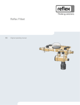
4.4 Function
1
Secondary tank (optional)
2
Primary tank
3
Vacuum spray pipe
WC
Make-up pipe
DC
Degassing line
• Gas-rich water from the system
• Degassed water to the system
EC
Expansion pipe
• Pipe to the expansion vessel
• Pipe from the expansion vessel
The device is a pressure maintaining station for heating and cooling water
systems. It is used for maintaining pressure, making-up and degassing the water
in heating and cooling systems. The device comprises a control unit consisting of
a controller with hydraulic system, vacuum spray pipe and at least one expansion
vessel.
Expansion vessel:
One primary tank and multiple optional secondary tanks may be connected. A
membrane separates the tanks into an air and a water space, preventing the
penetration of atmospheric oxygen into the expansion water. The "VE" pressure
compensation elbow connects the air space with the atmosphere. The primary
tank is hydraulically flexibly connected to the control unit. The function of the
"LIS" level measuring using a pressure pick-up is thus ensured.
Control unit:
The control unit comprises a control module and a hydraulic module.
• Control module
Comprising the Control Touch controller and the power connection unit.
All pressure maintenance, degassing and make-up processes within the
hydraulic module are monitored and controlled by the Control Touch
controller.
• Hydraulic module
The hydraulic module comprises the pump “PU”, the overflow valve
“PV/RKH1” and the make-up valve “WV/MKH1”.
The "PIS" pressure sensor records the pressure and the "LIS" pressure pick-up
registers the level; both values are indicated in the Control Touch display.
Interfaces enable the use of additional Control Touch functions see chapter 6.4.3
"RS-485 interface" on page 13 .
The device fulfils three functions:
Maintain pressure:
• The pressure in the facility system rises when the water is heated. When
the pressure set at the controller is exceeded, the "PV/RKH1" pressure relief
valve opens and drains water from the system into the primary tank, using
the "EC" expansion pipe. The pressure within the system drops. The
pressure in the facility system drops when the water cools. When the
pressure drops below the set value, the "PU" pump is activated and uses
the "EC" expansion pipe to transport water from the primary tank back into
the system. The pressure in the facility system rises. The controller ensures
that the pressure is maintained, further supported by the stabilisation
provided by the "MAG" pressure expansion vessel.
Degassing:
Two "EC" expansion pipes are required to degas the system water. One pipe is
intended for gas-rich water from the system, while one return pipe returns
the degassed water to the system. During the degassing action, the "PU"
pump and the "PV/RKH1" pressure relief valve are in operation. The pump
creates a vacuum in the spray pipe. • Gas-rich water is conveyed via
the degassing line connection from the facility system to the vacuum spray
pipe and degassed. Details see chapter "Sequence of a degassing cycle in
the vacuum spray pipe" on page 5 . This process can be applied in two
different variants (continuous and interval degassing).
Make-up with water for the facility system.
• When the water level in the primary tank falls below the minimum, the
"WV/MKH1" make-up valve opens and make-up into the tank continues
until the set level is again reached. During the make-up process, the
number of requests, the time and the make-up time within a cycle are
monitored. Using a FQIRA+ contact water meter, the system monitors each
individual make-up quantity and the overall make-up quantity.
The Servimat provides the following safety features:
• Optimisation of all pressure maintenance, degassing and make-up
sequences.
• No direct intake of air thanks to a regulation of the pressure
maintenance with automatic make-up.
• No circulation issues caused by free bubbles in the circuit water.
• Reduced corrosion damage due to oxygen removal from fill and
make-up water.
Sequence of a degassing cycle in the vacuum spray pipe
1
Create vacuum in the spray pipe
3
Discharge
2
Injection
4
Idling time
The degassing operation uses timer-controlled cycles. A cycle comprises the
following phases:
1. Create vacuum in the spray pipe.
The pump starts and conveys water from the vacuum spray pipe. The
pump transports more water from the spray pipe than can be transported
via the connection lines of the water make-up. A vacuum is created.
2. Injection
Opening of the “PV” overflow valves in the “DC” degassing line routes gas-
rich water into the spray pipe. It is atomised by nozzles in the spray pipe.
The atomised water is degassed in the vacuum of the vacuum spray pipe
because of the large surface area resulting from the atomisation. The
degassed water is returned to the facility system via the vacuum pump.
The pressure relief valve means that the pump is set to a constant working
pressure. The working pressure depends on the respective facility system.

Technical data
6 — English
Servimat M/L — 28.01.2021
3. Discharge
The pump shuts down. The pressure in the facility system causes more
water to be injected into the vacuum spray pipe and degassed. The water
level in the vacuum spray pipe rises. The gases released in the vacuum
spray pipe are released into the ambient atmosphere via the degassing
valves.
4. Idling time
When the gas has been discharged, the device will remain idling until the
next cycle is started.
Degassing programmes
The device controller regulates the degassing process. The controller monitors
the operating states and outputs them to the display.
The controller provides 2 different degassing programmes for selection and
adjustment:
• Continuous degassing
For continued degassing over several hours or days in a sequence of
degassing cycles without idling periods. This degassing programme must
be selected after commissioning and repairs.
• Interval degassing
This comprises a limited number of degassing cycles. There is an idling
time between the intervals. This degassing programme must be selected
for continuous operation.
Make-up variants
The filling level in the tank is measured using the LIS Levelcontrol. If the level
falls below the pre-set minimum level, then at a specified level, make-up water is
fed in a controlled manner into the tank.
a umso besser
Servimat M/L connection diagram
1
Bladder expansion vessel
2
Gas-rich water inlet
3
Make-up pipe
4
Make-up valve
5
Control ball valve (RKH)
6
Vacuum spray pipe
7
Feed and drain cock
8
Motorized ball valve (MKH) to the tank
9
3-way motorized ball valve
Hydraulic connection between tank, vacuum spray pipe and pump
(system)
10
Pump
11
Degassed water outlet
12
Pipe to the pressure expansion vessel
13
Pipe from the pressure expansion vessel
4.5 Scope of delivery
The scope of delivery is described in the shipping document and the content is
shown on the packing.
Immediately after receipt of the goods, please check the shipment for
completeness and damage. Please notify us immediately of any transport
damage.
Basic pressure maintenance equipment:
• The device on a pallet.
–Control unit
–Corrugated sheet hose with union angle (enclosed with control unit)
• “DV” degassing valve of the spray pipe, carton packed.
–Primary tank with accessories packed on the tank mounting.
• "VE" ventilation
• Degassing valve for the “DV” tank
• Reducing coupling
• "LIS" pressure pick-up
–Plastic sleeve with operating manual
4.6 Optional equipment and accessories
The following optional equipment and accessories are available for this device:
• Heat insulation for the primary tank
• Secondary tanks
–Accessories are packed on the tank mounting
• "VE" ventilation
• "DV" degassing valve
• Reducing coupling
• Additional equipment with unsupervised-operation BOB-pipe for “TAZ+”
temperature limiter
• Fillset for make-up with water.
–Fillset with integrated system isolator, water meter, dirt trap, and
locking mechanisms for the "WC" make-up pipe.
• Fillset Impulse with FQIRA+ contact water meter for make-up with water.
• Fillsoft for softening the make-up water from the potable water supply
system.
–The Fillsoft is installed between the Fillset and the device. The device
controller evaluates the make-up quantities and signals the required
replacement of the softening cartridges.
• Enhancements for the device controller:
–I/O module for standard communication.
–Communication module for external operation of the controller
–Master-Slave-Connect for master controllers for maximum 10
devices.
–Combined switching to increase capacity and parallel switching of 2
hydraulically directly connected systems
–Bus modules:
• Lonworks Digital
• Lonworks
• Profibus DP
• Ethernet
• Diaphragm rupture monitor.
Note!
Separate operating instructions are supplied with accessories.
5 Technical data
5.1 Control unit
Note!
The following values apply for all control units:
–Permissible flow temperature:
–Permissible operating temperature:
–Permissible ambient temperature:
120 °C
70 °C
0 °C – 45 °C

Installation
Servimat M/L — 28.01.2021
English — 7
Type
Power output
(kW)
Power supply
(V / Hz , A)
Degree of
protection
Number of RS-485
interfaces
I/O module
Electrical voltage
control unit
(V, A)
Noise level
(dB)
Weight
(kg)
Servimat M
1.1
230 / 50, 5
IP 54
1
No
230, 2
55
37
Servimat L
1.1
230 / 50, 5
IP 54
1
No
230, 2
55
53
5.2 Dimensions and connections
Type
Weight
(kg)
Height
(mm)
Width
(mm)
Depth
(mm)
Device connection
Degassing system
connection
Make-up
connection
Servimat M
36
1215
685
440
Internal thread 1 "
Internal thread 1 "
Internal thread ½ "
Servimat L
42
1215
600
525
Internal thread 1 "
Internal thread 1 "
Internal thread ½ "
5.3 Operation
Type
System volume
(100% water)
(m³)
System volume
(50% water 50% glycol)
(m³)
Working pressure
(bar)
Permissible operating gauge
pressure
(bar)
Operating temperature
(°C)
Servimat M
220
–
0.5 – 4.5
8
>0 – 70
Servimat L
220
–
0.5 – 7.2
10
>0 – 70
Standard values for the maximum "Va" system volume to be degassed under
extreme conditions during commissioning at a nitrogen reduction from 18 mg/l
to 10 mg/l.
1
Continuous degassing "t" [h]
2
System volume "Va" [m3]
5.4 Tanks
Primary tank
Secondary tank
Note!
Optional heat insulation is available for primary tanks, see chapter 4.6
"Optional equipment and accessories" on page 6 .
Type
Ø “D”
(mm)
Weight
(kg)
Connection
(inches)
H
(mm)
h
(mm)
6 bar - 200
634
37
G1
1060
146
6 bar - 300
634
54
G1
1360
146
6 bar - 400
740
65
G1
1345
133
Type
Ø “D”
(mm)
Weight
(kg)
Connection
(inches)
H
(mm)
h
(mm)
6 bar - 500
740
78
G1
1560
133
6 bar - 600
740
94
G1
1810
133
6 bar - 800
740
149
G1
2275
133
6 bar -
1000/740
740
156
G1
2685
133
6 bar -
1000/1000
1000
320
G1
2130
350
6 bar - 1500
1200
465
G1
2130
350
6 bar - 2000
1200
565
G1
2590
350
6 bar - 3000
1500
795
G1
2590
380
6 bar - 4000
1500
1080
G1
3160
380
6 bar - 5000
1500
1115
G1
3695
380
6 Installation
DANGER
Risk of serious injury or death due to electric shock.
If live parts are touched, there is risk of life-threatening injuries.
• Ensure that the system is voltage-free before installing the device.
• Ensure that the system is secured and cannot be reactivated by other
persons.
• Ensure that installation work for the electric connection of the device is
carried out by an electrician, and in compliance with electrical engineering
regulations.
CAUTION
Risk of injury due to pressurised liquid
If installation, removal or maintenance work is not carried out correctly, there is a
risk of burns and other injuries at the connection points, if pressurised hot water
or hot steam suddenly escapes.
• Ensure proper installation, removal or maintenance work.
• Ensure that the system is de-pressurised before performing installation,
removal or maintenance work at the connection points.
CAUTION
Risk of burns on hot surfaces
Hot surfaces in heating systems can cause burns to the skin.
• Wear protective gloves.
• Please place appropriate warning signs in the vicinity of the device.

Installation
8 — English
Servimat M/L — 28.01.2021
CAUTION
Risk of injury due to falls or bumps
Bruising from falls or bumps on system components during installation.
• Wear personal protective equipment (helmet, protective clothing, gloves,
safety boots).
Note!
Confirm that installation and start-up have been carried out correctly
using the installation, start-up and maintenance certificate. This action
is a prerequisite for the making of warranty claims.
–Have the Reflex Customer Service carry out commissioning and
the annual maintenance.
6.1 Incoming inspection
Prior to shipping, this device was carefully inspected and packed. Damages
during transport cannot be excluded.
Proceed as follows:
1. Upon receipt of the goods, check the shipment for
• completeness and
• possible transport damage.
2. Document any damage.
3. Contact the forwarding agent to register your complaint.
6.2 Preparatory work
Condition of the delivered device:
• Check all screw connections of the device for tight seating. Tighten the
screws as necessary.
Preparing the device installation:
• No access by unauthorised personnel.
• Frost-free, well-ventilated room.
–Room temperature 0 °C to 45 °C (32 °F to 113 °F).
• Level, stable flooring.
–Ensure sufficient bearing strength of the flooring before filling the
tanks.
–Ensure that the control unit and the tanks are installed on the same
level.
• Filling and dewatering option.
–Provide a DN 15 filling connection according to DIN 1988 - 100 and
En 1717.
–Provide an optional cold water inlet.
–Prepare a drain for the drain water.
• Electric connection 230 V~, 50/60 Hz, 16 A with upstream ELCB: Tripping
current 0.03 A.
• Use only approved transport and lifting equipment.
–The load fastening points at the tanks must be used only as
installation resources.
Note!
Comply with the Reflex planning directive.
–During planning, take into account that the working range of the
device must be between the "pa" supply pressure and the "pe"
final pressure in the working range of the pressure maintenance
system.
6.3 Execution
ATTENTION
Damage due to improper installation
Additional device stresses may arise due to the connection of pipes or system
equipment.
• Ensure that pipes are connected from the device to the system without
them being stressed or strained.
• If necessary, provide support structures for the pipes or equipment.
For installation, proceed as follows:
• Position the device.
• Complete the primary tank and the optional secondary tanks.
• Create the water-side connections of the control unit to the system.
• Create the interfaces according to the terminal plan.
• Install the water connections between optional secondary tanks to each
other and to the primary tank.
Notice!
For installation, note the operability of the valves and the inlet options
of the connecting lines.
6.3.1 Fitting the add-on components for the vacuum spray pipe
Fit the "DV" degassing valve with pre-assembled check valve on the "VT" vacuum
spray pipe.
For optimum reliability, we recommend braided sealing tape (PTFE) or pipe
sealing cord (polyamide ww. PTFE) as a seal.
Check all screw fittings of the device for proper seating.
6.3.2 Positioning
Specify the position of the control unit and primary tank:
• Servimat:
The control unit can be installed on either side or in front of the primary
tank. The distance of the control unit to the primary tank results from the
connection set supplied.
6.3.3 Installation of add-on components for the tanks
The add-on components are packed in plastic bags and attached to the base of
the tanks.
• Pressure compensation elbow (1).
• Reflex Exvoid with pre-fitted check valve (2)
• "LIS" pressure pick-up
For add-on components, proceed as follows:
1. Install the Reflex Exvoid (2) at the connection of the corresponding tank.
For optimum reliability, we recommend braided sealing tape (PTFE) or pipe
sealing cord (polyamide ww. PTFE) as a seal.
2. Remove the protective cap from the degassing valve.
3. Use the compression fitting to install the pressure compensation elbow (1)
for ventilation at the tanks.
Note!
Install the "LIS" pressure pick-up only after finalising the installation of
the primary tank, see chapter 6.3.6 "Fitting the level sensor" on page 10 .
Note!
To ensure fault-free operation, do not seal off the ventilation.

Installation
Servimat M/L — 28.01.2021
English — 9
6.3.4 Tank installation
ATTENTION
Damage due to improper installation
Additional device stresses may arise due to the connection of pipes or system
equipment.
• Ensure that pipes are connected from the device to the system without
them being stressed or strained.
• If necessary, provide support structures for the pipes or equipment.
ATTENTION
Device damage resulting from dry running of the pump
If the pump is incorrectly connected, there is a risk of dry-running.
• Ensure that the connections for the overflow collector and the pump are
not interchanged.
• Ensure correct connection of the pump to the primary tank.
(All data in mm)
Comply with the following notes regarding the installation of the primary tank
and the secondary tanks.
• All flange openings at the tanks are viewing and maintenance openings.
Install the primary tank and the secondary tanks, if provided, with
sufficient spaces at the sides and the top.
• Install the tanks on a level surface.
• Ensure rectangular and free-standing position of the tanks.
• If you use secondary tanks in addition to the primary tank, ensure that all
tanks are of the same type and dimensions.
• Do not attach the tanks to the flooring to ensure the functioning of the
"LIS" level sensor.
• Install the control unit on the same level as the tanks.
1
Adhesive label
3
"Pump" connection set
2
"Overflow collector" connection set
4
Secondary tank connection
set
• Align the primary tank.
–The distance of the primary tank to the control unit must match the
length of the connection set.
• Connect the connection set (2) and (3) with the screw fittings and gaskets
to the connections at the lower tank flange of the primary tank.
–Ensure that you connect the connection set for the overflow collector
to the connection (2) below the label (1).
• Interchanging the connections may cause the pump to run dry.
–For tanks up to 740 mm Ø:
• Connect the connection set (2) and (3) to the two free 1-inch
barrel nipples at the tank flange.
• Connect the connection set (4) of the secondary tank to the T-
joint at the outlet of the tank flange.
–For tanks from 1000 mm Ø:
• Connect the connection set (2) to the 1-inch barrel nipple of
the tank flange.
• Connect the connection sets (3) and (4) to the T-joint at the 1-inch barrel
nipple of the tank flange.
Note!
If necessary, install the supplied connection set (4) at the optional
secondary tank. Connect the connection set (4) with a user-supplied
flexible pipeline to the primary tank.
6.3.4.1 Connection to the facility system
CAUTION
Hot water vapour can cause burns to skin and eyes.
Hot steam can escape from the safety valve. The hot steam will cause scalding of
the skin and eyes.
• Ensure that the blow-off line of the safety valve is routed so that injuries
are not possible.
ATTENTION
Damage due to improper installation
Additional device stresses may arise due to the connection of pipes or system
equipment.
• Ensure that pipes are connected from the device to the system without
them being stressed or strained.
• If necessary, provide support structures for the pipes or equipment.
6.3.4.2 Degassing line to the system
The device requires two "DC" degassing lines to the system. One degassing line is
intended for gas-rich water from the system, and the other one serves to return
the degassed water to the system. Shut-off devices for both degassing lines have
been pre-installed at the device. The connections of the degassing lines must be
made within the main flow volume of the facility system.
Device installation in a heating system – Pressure maintenance with diaphragm-
type expansion vessel

Installation
10 — English
Servimat M/L — 28.01.2021
1
Optional equipment and accessories see chapter 4.6 "Optional
equipment and accessories" on page 6
2
Heat generator
3
Servimat
4
Primary tank connection set
5
Primary tank
6
Reflex rapid-action coupling R 1 x 1
7
Secondary tank
EC
Degassing line
• Gas-rich water from the system
• Degassed water to the system
LIS
Level sensor
WC
Make-up pipe
MAG
Expansion vessel
If required, install a bladder expansion vessel MAG ≥ 140 litres (Reflex N, for
example). It reduces the switching frequency and can be also used in the
individual protection of the heat generators. The p0 setting of the bladder
expansion vessel (MAG) should be identical to the p0 setting of the controller.
According to DIN / EN 12828, the installation of shut-off devices between the
appliance and the heat generator is required for heating systems. Otherwise
secure locking mechanisms must be fitted.
Installation detail of the "DC" degassing line
Connect the "DC" degassing lines as shown below.
• Ensure that particulate dirt cannot enter and thus create an overload of the
"ST" dirt trap.
• Connect the degassing line for gas-rich water upstream of the degassing
line for degassed water in system direction of flow.
• The water temperature must be in the range 0 °C – 70 °C. The return line
side should be preferred for heating systems. This ensures the permissible
temperature range for degassing.
6.3.5 Fitting the thermal insulation
Install the optional thermal insulation (2) around the primary tank (1) and close
the insulation with the zip fastener.
Note!
For heating systems, insulate the primary tank and the "EC" expansion
lines against heat loss.
–Thermal insulation is not required for either the primary tank top
or the secondary tank.
Note!
On-site, install thermal insulation when condensate forms.
6.3.6 Fitting the level sensor
ATTENTION
Damage to the pressure load cell due to unprofessional installation
Incorrect installation may result in damage to the "LIS" level sensor,
malfunctioning and incorrect measurements from the pressure load cell.
• Comply with the instructions regarding the installation of the pressure
load cell.
The "LIS" level sensor uses a pressure load cell. This pressure pick-up is to be
installed after the primary tank has been placed at its final position, see
chapter 6.3.4 "Tank installation" on page 9 . Comply with the following
instructions:
• Remove the transport securing device (squared timber) at the vessel base
of the primary tank.
• Replace this transport securing device with the pressure load cell.
–In the case of a tank volume of 1000 l (Ø 1000 mm) or more, use the
supplied screws to attach the pressure load cell at the vessel base of
the primary tank.
• Avoid shock-type loading of the pressure load cell by, for example,
subsequent alignment of the vessel.
• Use flexible hoses to connect the primary tank and the first secondary tank.
–Use only the supplied connection sets, see chapter 6.3.4 "Tank
installation" on page 9 .
• Perform a null balancing of the filling level when the primary tank is
aligned and fully emptied, see chapter 9.3.1 "Customer menu" on page 18 .
Standard values for level measurements:
Primary tank
Measuring range
200 l
0 – 4 bar
300 – 500 l
0 – 10 bar
600 – 1000 l
0 – 25 bar
1500 – 2000 l
0 – 60 bar
3000 – 5000 l
0 – 100 bar
6.4 Electrical connection
DANGER
Risk of serious injury or death due to electric shock.
If live parts are touched, there is risk of life-threatening injuries.
• Ensure that the system is voltage-free before installing the device.
• Ensure that the system is secured and cannot be reactivated by other
persons.
• Ensure that installation work for the electric connection of the device is
carried out by an electrician, and in compliance with electrical engineering
regulations.

Installation
Servimat M/L — 28.01.2021
English — 11
For the electrical connection, you must differentiate between a connection
component and an operating component.
1
Connection unit
2
Covers of the operating unit (folding)
• RS-485 interfaces
• Pressure output
3
Operating unit (Control Touch controller)
4
Cable bushings
5
Covers of the connection unit (folding)
• Supply and fusing
• Floating contacts
• Aggregate connection
The following descriptions apply to standard systems and are limited to the
necessary user-provided connections.
1. Shut down the system and secure it against unintentional reactivation.
2. Remove the covers.
DANGER – electric shock! Risk of serious injury or death due to electric
shock. Some parts of the device's circuit board may still be live with 230 V
even after the device has been physically isolated from the power supply
by pulling out of the mains plug. Before you remove the covers, completely
isolate the device controller from the power supply. Verify that the main
circuit board is voltage-free.
3. Insert a suitable screwed cable gland for the cable bushings at the rear of
the connection component. M16 or M20, for example.
4. Thread all cables to be connected through the cable glands.
5. Connect all cables as shown in the terminal diagrams.
–Connection unit, see chapter 6.4.1 "Terminal plan, connection
component" on page 11 .
–Operating unit, see chapter 6.4.2 "Terminal plan, operating unit" on
page 12 .
–When providing fusing for the appliance, note its connected load, see
chapter 5 "Technical data" on page 6 .
6. Install the cover.
7. Connect the mains plug to the 230 V power supply.
8. Activate the system.
The electrical connection is completed.
6.4.1 Terminal plan, connection component
1
Pressure
3
Fuses
2
Level
Terminal
number
Signal
Function
Wiring
Supply
X0/1
L
Supply 230 V, maximal 16 A
User supplied
X0/2
N
X0/3
PE
X0/1
L1
Supply 400 V, maximal 20 A
User supplied
X0/2
L2
X0/3
L3
X0/4
N
X0/5
PE
Terminal
number
Signal
Function
Wiring
Circuit board
1
PE
Voltage supply
Factory-
provided
2
N
3
L
4
Y1
“Safe Control” motorized ball
valve for make-up (MKH1) WV
Factory-
provided
5
N
6
PE
7
Y2
Motorized ball valve to the tank
(MKH2)
Factory-
provided
8
N
9
PE

Installation
12 — English
Servimat M/L — 28.01.2021
Terminal
number
Signal
Function
Wiring
10
Y3
3-way motorized ball valve
Factory-
provided
11
N
12
PE
13
Dry-run protection message
(floating)
User supplied
14
15
M1
PU 1 pump
Factory-
provided
16
N
17
PE
18
M2
---
---
19
N
20
PE
21
FB1
Pump 1 voltage monitoring
Factory-
provided
22a
FB2a
Pump 2 voltage monitoring
Factory-
provided
22b
FB2b
External make-up request
together with 22a
Factory-
provided
23
NC
Group message (floating)
User supplied
24
COM
25
NO
27
M1
Flat plug for supply, pump 1
Factory-
provided
31
M2
Flat plug for supply, pump 2
Factory-
provided
35
+18 V (blue)
Analogue input, LIS level
measuring
at the primary tank
User supplied
36
GND
37
AE (brown)
38
PE (shield)
39
+18 V (blue)
Analogue input, "PIS" pressure
measuring
at the primary tank
User, optional
40
GND
41
AE (brown)
42
PE (shield)
43
+24 V
Digital inputs
User, optional
44
E1
E1: Contact water meter
Factory-
provided
45
E2
Insufficient water switch E2
(LSL)
---
51
GND
---
---
52
+24 V (supply)
53
0 – 10 V
(correcting
variable)
54
0 – 10 V
(feedback)
55
GND
Pressure relief valve (control
ball valve RKH1)
Factory-
provided
56
+24 V (supply)
57
0 – 10 V
(correcting
variable)
58
0 – 10 V
(feedback)
6.4.2 Terminal plan, operating unit
1
RS-485 interfaces
2
I/O interface
3
I/O interface (reserve)
4
Micro SD card
5
10 V supply
6
Analogue outputs for Pressure and Level
7
Battery compartment
8
Bus module supply voltage
9
RS–485 connection
10
RS–485 connection
Terminal number
Signal
Function
Wiring
1
A
RS-485 interface
S1 networking
User
supplied
2
B
3
GND S1
4
A
RS-485 interface
S2 modules: Expansion or
communication module
User
supplied
5
B
6
GND S2
7
+5 V
I/O interface: Interface to the
main board
Factory
8
R × D
9
T × D
10
GND IO1
11
+5 V
I/O interface: Interface to the
main board
(reserve)
---
12
R × D
13
T × D
14
GND IO2
15
10 V~
10 V supply
Factory
16
17
FE
18
Y2PE
(shielding)
Analogue outputs: Pressure
and Level
Standard 4 – 20 mA
User
supplied
19
Pressure
20
GNDA
21
Level
22
GNDA

Commissioning
Servimat M/L — 28.01.2021
English — 13
6.4.3 RS-485 interface
Use the S1 and S2 RS-485 interfaces to retrieve all controller data and to enable
the communication with control centres or other devices.
• S1 interface
–A maximum 10 devices can be used in a master-slave linked circuit
via the this interface.
• S2 interface
–"PIS" pressure and "LIS" level.
–Operating modes of the "PU" pumps.
–Operating state of the control ball valve (RKH1) in the pressure relief
pipe.
– “Safe Control” operating state (MKH1) of the make-up.
–Values of the "FQIRA +" contact water meter.
–All messages, see chapter 9.4 "Messages" on page 21 .
–All entries in the fault memory.
The following accessories are available for interface communication.
–Bus modules
• Lonworks Digital
• Lonworks
• Profibus-DP
• Ethernet
• Optional I/O module, see chapter 6.4.3 "RS-485 interface" on page 13
.
Note!
If required, please contact the Reflex Customer Service for the protocol
of the RS-485 interface, details of the connections and information
about the accessories offered.
6.4.3.1 Connecting the RS-485 interface
Main circuit board of the Control Touch controller.
1
Connection terminals for RS-485 connection
2
Dip switch 1
Proceed as follows:
1. Use a screened cable to connect the RS-485 interface to the main circuit
board.
• S 1
–Terminal 1 (A+)
–Terminal 2(B-)
–Terminal 3(GND)
2. Connect the cable screen at one side.
• Terminal 18
3. Activate the terminator on the main circuit board.
• Dip switch 1
Note!
Activate the terminator when the device is at the beginning or the end
of the RS-485 network.
6.5 Installation and commissioning certificate
Data shown on the type plate:
P0
Type:
PSV
Manufacturing number:
This device has been installed and commissioned in accordance with the
instructions provided in the operating manual. The settings in the controller
match the local conditions.
Note!
When any factory-set values of the device are changed, you must enter
this information in the Maintenance certificate, see chapter 10.5
"Maintenance certificate " on page 24 .
For the installation
Place, date
Company
Signature
For the commissioning
Place, date
Company
Signature
7 Commissioning
CAUTION
Risk of burns on hot surfaces
Hot surfaces in heating systems can cause burns to the skin.
• Wear protective gloves.
• Please place appropriate warning signs in the vicinity of the device.
Note!
Confirm that installation and start-up have been carried out correctly
using the installation, start-up and maintenance certificate. This action
is a prerequisite for the making of warranty claims.
–Have the Reflex Customer Service carry out commissioning and
the annual maintenance.
7.1 Checking the requirements for commissioning
The device will be ready for initial commissioning when the tasks described in
the "Installation" chapter have been completed. The system designer or an
assigned expert is responsible for carrying out the commissioning. Commission
the storage tank according to the information in the corresponding installation
manual. Note the following information on initial commissioning:
• The control unit is connected to the primary tank and the secondary tanks,
if provided.
• The water connections of the tanks to the facility system are established.
• The tanks are not filled with water.
• The valves for emptying the tanks are open.
• The water-side connection of the device to the make-up supply has been
created and is operational.
• The connection pipes of the device have been purged and cleaned of
welding residue and dirt before commissioning.
• The entire facility system is filled with water and all gases have been
vented in order to ensure a circulation through the entire system.
• The electrical connection has been created according to applicable
national and local regulations.
7.2 Determining the P0 minimum operating pressure for the
controller
The "p0" minimum operating pressure is determined by the location of the
pressure maintaining device. The controller calculates the switching points for
the "PV" control ball valve and the "PU" pumps from the minimum operating
pressure.

Commissioning
14 — English
Servimat M/L — 28.01.2021
Description
Calculation
pst
Static pressure
= static head (hst)/10
p0
Minimum operating pressure
= pst + 0.2 bar
pa
Supply pressure (pump "ON")
= p0 + 0.3 bar
Static pressure range (control ball
valve RKH1 "CLOSED" / Pump
"OFF")
= p0 + 0.5 bar
pe
Final pressure (control ball valve
RKH1 “ON”)
≤ pSv - 0.5 bar (for pSv ≤ 5.0 bar)
≤ pSv x 0.9 (for pSv > 5.0 bar)
pSv
Safety valve actuating pressure
= p0 + 1.2 bar (for pSv ≤ 5.0 bar)
= 1.1 x p0 + 0.8 bar
(for pSv > 5.0 bar)
1
Suction pressure maintenance
• Device on the suction side of the system's circulating pump
2
Final pressure maintenance
• Device on the discharge side of the system's circulating pump
The "P0" minimum operating pressure is calculated as follows:
Calculation
Description
pst
= hst/10
hst in metres
pD
0.0 bar
for safety temperatures ≤ 100 °C
(212° F)
0.5 bar
for safety temperatures = 110°C
(230° F)
dp
60 - 100 % of the differential
pressure of the circulating pump
Depending on the hydraulics
P0
≥ pst + pD + 0.2 bar* (suction
pressure maintenance)
Enter the calculated value in the start
routine of the controller, see
chapter 9.3 "Modifying the controller's
start routine" on page 17 .
≥ pst + pD + dp + 0.2 bar* (final
pressure maintenance)
* Addition of 0.2 bar recommended, no addition in extreme cases
Calculation example for "P0" minimum operating pressure:
Heating system: Static height 18 m, run-on temperature 70 °C (158° F), safety
temperature 100 °C (212° F).
Example calculation for suction pressure maintenance:
P0 = pst + pD + 0.2 bar*
pst = hst/10
pst=18 m/10
pst = 1.8 bar
pD = 0.0 bar at a safety temperature of 100 °C (212° F)
P0 = 1.8 bar + 0 bar + 0.2 bar
P0 = 2.0 bar
Note!
–The initial and final pressure of the following components must
not overlap with the actuating pressure of the safety valve.
• Control ball valve RKH1
• Pumps
–The actuating pressure must not fall below the minimum value of
the actuating pressure of the safety valve.
Note!
Avoid dropping below the minimum operating pressure. Vacuum,
vaporisation and the formation of vapour bubbles are thus excluded.
7.3 Filling the device with water and venting
CAUTION
Risk of burns
Escaping hot medium can cause burns.
• Maintain a sufficient distance from the escaping medium.
• Wear suitable personal protective equipment (safety gloves and goggles).
1
"PI" vacuum gauge
5
"PU" pump
2
"DV" degassing valve
WC
Make-up pipe
3
"FD" feed and drain cock
DC
Degassing lines
4
"AV" venting screw
EC
Expansion pipe
1. Use the facility system to fill the device.
–After you have opened the "DC" ball valve, the vacuum spray pipe
will autonomously fill if the facility system provides sufficient water.
2. Optional
–Use the feed and drain cock to fill water into the device (3).
–Connect a hose at the feed and drain cock (3) of the "VT" vacuum
spray pipe.
3. Fill the vacuum spray pipe with water.
–Air escapes via the degassing valve (2) and the water pressure can be
read at the vacuum gauge (1).

Commissioning
Servimat M/L — 28.01.2021
English — 15
Vent the pump:
4. Turn the venting screw (1) until air or a water/air mixture escapes.
5. If required, use a screwdriver to rotate the pump at the fan wheel of the
pump motor.
CAUTION – Risk of injury due to pump start-up! Hand injury due to a
pump start-up. Switch the pump to a zero-volts state before turning the
pump motor at the fan wheel with a screwdriver.
CAUTION – Device damage. Pump damage due to a pump start-up. Switch
the pump to a zero-volts state before turning the pump motor at the fan
wheel with a screwdriver.
–Water/air mixtures are removed from the pump.
6. Re-tighten the venting screw when only water escapes.
7. Close the feed and drain cock.
Filling and venting is concluded.
Note!
The "PU" pump must not be switched on when the device is filled with
water.
Note!
Do not fully unscrew the venting screw. Wait until air-free water
appears. Repeat the venting process until the "PU" pump is fully vented.
7.4 Vacuum test
Carefully perform the vacuum test to ensure the proper functioning of the
device.
Proceed as follows:
1. Switch to Manual mode.
• For more information about Manual mode, see chapter 8.1.2 "Manual
mode" on page 16 .
2. Close RKH1 (control ball valve) from the system feed line in controller
“Manual mode”.
3. Close MKH2 (motorised ball valve) to the tank in controller “Manual mode”.
4. Close the “Safe Control” make-up valve in the make-up pipe.
5. Open the 3-way motorized ball valve in the direction of the pump/spray
pipe.
6. Generate a vacuum in controller manual mode.
7. After 10 minutes, recheck the "PI“ vacuum gauge. The pressure must not
change. If the pressure has increased, check the device for leaks.
• All screw connections at the "VT“ vacuum spray pipe.
• The "DV" degassing valve at the "VT" vacuum spray pipe.
• The venting screw at the "PU" pump.
8. After successful conclusion of the vacuum test, open the ball valve (2).
9. If the controller displays the "Insufficient water" error message,
acknowledge the message via button "OK".
Note!
The obtainable vacuum corresponds to the saturation pressure at the
existing water temperature.
–At 10 °C, a vacuum of approximately. -1 bar can be obtained.
Note!
Repeat steps 5 to 6 until no further pressure rise is observed.
7.5 Filling the tanks with water
The following information applies to the devices:
• Control unit and primary tank.
• Control unit and primary tank and one secondary tank.
• Control unit and primary tank and more than one secondary tanks.
Facility system
System temperature
Filling level of primary tank
Heating system
≥ 50 °C (122° F)
Approx. 30 %
Cooling system
< 50 °C (122° F)
Approx. 50 %
7.5.1 Filling with a hose
Preferably use a water hose to fill the primary tank with water when the
automatic make-up device is not yet connected.
• Use a vented water hose filled with water.
• Connect the water hose to the external water supply and the "FD" feed and
drain cock (1) at the primary tank.
• Check whether the shut-off valves between control unit and primary tank
are open (supplied pre-wired in open position).
• Fill the primary tank with water until the filling level has been reached.
7.5.2 Filling using Safe Control in the make-up pipe
1. Use the "Manual mode" button to switch to "Manual" mode.
2. Open the “WV make-up valve” and “MKH2” via the corresponding buttons
until the specified filling level is reached.
–Continuously monitor this process.
–If a high-water alarm is generated, the make-up valve “WV make-up
valve” is automatically closed.
7.6 Starting Automatic mode
Notice!
The "ST" dirt trap in the "DC" degassing line must be cleaned after the
expiry of the continuous degassing time at the latest, see chapter 10.3.1
"Cleaning the dirt trap" on page 23 .
Note!
The commissioning process is now concluded.

Operation
16 — English
Servimat M/L — 28.01.2021
8 Operation
8.1 Operating modes
8.1.1 Automatic mode
i
After successful initial commissioning, start automatic operation of the device.
The controller monitors the following functions:
• Maintain pressure
• Compensate expansion volume
• Degas
• Automatic make-up
To start the Automatic mode, proceed as follows:
1. Press "AUTO“.
–The pumps and pressure relief valves are regulated so that the
pressure remains constant to within ± 0.2 bar.
–Faults are displayed and evaluated.
Automatic mode is activated.
Select a degassing programme for Automatic mode. The Customer menu
provides two different degassing programmes for selection, see chapter 9.3.4
"Degassing programmes – overview" on page 20 .
• Continuous degassing.
• Interval degassing.
For selection of degassing programmes, see chapter 9.3.5 "Setting degassing
programmes" on page 20 .
The controller displays the selected degassing programme in the message line.
8.1.2 Manual mode
The manual mode is intended for test and maintenance tasks.
Manual mode allows you to select the following functions and to perform a test
run:
• "PU" pump.
• The pressure relief valve (opening of RKH1 and MKH2).
• The “WV” Safe Control for the make-up.
• The 3-way motorized ball valve “MKH3”
You have the option to simultaneously switch multiple functions and to test
them in parallel. Switch the function on and off by touching the corresponding
button.
• The button is highlighted green: The function is switched off.
• Press the desired button.
• The button is highlighted blue: The function is switched on.
Proceed as follows:
1. Press "Manual mode“.
2. Select the desired function:
• “PU” = Pump
• “RKH1+MKH2” = Pressure relief valve
• “WV1” = Safe Control make-up valve
• “MKH3” = Opening/closing of tank/spray pipe to the system
The change in the filling level and the tank pressure are indicated on the display.
Note!
Manual operation can not be performed if safety-relevant parameters
are exceeded.
–Switching is blocked if safety-relevant settings are exceeded.
8.1.3 Stop mode
Except for the display of information, the device is non-functional in Stop mode.
Function monitoring is stopped.
The following functions are deactivated:
• The pump is switched off.
• The 2-way motorized ball valve in the pressure relief pipe is closed.
• The 2-way motorized ball valve to the tank is closed.
• The 3-way motorized ball valve in the degassing line is closed to the spray
pipe.
To start Stop mode operation, proceed as follows:
• Touch "STOP".
Note!
The system returns an alarm if the Stop mode is activated for more than
4 hours.
–If "Volt free contact?" in the Customer menu is set to "Yes", the
system outputs the alarm to the group alarm contact.
8.2 Restarting
CAUTION
Risk of injury due to pump start-up
Hand injuries may occur when the pump starts up if you turn the pump motor at
the impeller using a screwdriver.
• Switch the pump to a zero-volts state before turning the pump at the fan
wheel with a screwdriver.
ATTENTION
Device damage due to pump start-up
Pump damage may occur when the pump starts up if you turn the pump motor
at the impeller using a screwdriver.
• Switch the pump to a zero-volts state before turning the pump at the fan
wheel with a screwdriver.
After an extended standstill time (the device is de-energised or in Stop mode),
the pumps may jam. For this reason, use a screwdriver to rotate the pumps at the
fan wheel of the pump motors before restarting.
Note!
A jamming of the pumps is prevented during operation thanks to forced
starting action (after 24 hours).

Controller
Servimat M/L — 28.01.2021
English — 17
9 Controller
9.1 Operator panel
1
Message line
8
Display value
2
"▼"/ "▲" buttons
• Set digits.
9
"Manual mode" button
• For function tests.
3
""/"" buttons
• Select digits.
10
"Stop mode" button
• For commissioning.
4
"OK" button
• Confirm/acknowledge
input.
• Browse in the menu.
11
"Automatic mode" button
• For continuous operation.
5
"Up" and "Down" scroll bar
• "Scroll" in the menu.
12
"Set-up menu" button
• For setting parameters.
• Fault memory.
• Parameter memory.
• Display settings.
• Primary tank information.
• Software version
information.
6
"Scroll back" button
• Cancel.
• Page back to the main
menu.
7
"Display help texts" button
• Opens help texts.
13
"Info menu" button
• Displays general
information.
9.2 Calibrating the touch screen
You can calibrate the touch screen when touching the desired buttons does not
work satisfactorily.
1. Switch the device off at the main switch.
2. Touch and hold the touch field with your finger.
3. Switch on the main switch while touching the touch field.
–When starting the program, the controller automatically switches to
the "Update/Diagnostics" function.
4. Touch the "Touch calibration" button.
5. Touch the displayed crosses on the touch screen after each other.
6. Switch the device off and on again at the main switch.
The touch screen is fully calibrated.
9.3 Modifying the controller's start routine
Note!
For handling the operator panel see chapter 9.1 "Operator panel" on
page 17
The start routine is used to set the required parameters for the device initial
commissioning. It commences with the first activation of the controller and can
be run only once. Parameter changes or checks are possible after the start
routine in the customer menu is exited, see chapter 9.3.1 "Customer menu" on
page 18 .
A three-digit PM code is assigned to the setting options.
Step
PM code
Description
1
Start of the start routine
2
001
Select the language
3
Remember: Prior to installation and commissioning, read
the operating manual!
4
005
Set the "PO" minimum operating pressure, see chapter 7.2
"Determining the P0 minimum operating pressure for the
controller" on page 13 .
5
002
Set the time
6
003
Set the date
7
121
Select the primary tank nominal volume
8
Null balancing: The primary tank must be empty!
The system checks whether the signal from the level sensor
matches the selected primary tank
9
End of the start routine. The stop mode is active.
The system automatically displays the first page of the start routine when you
switch on the device for the first time.
1. Press "OK“.
–The start routine moves to the next page.
2. Select the required language and conform your entry with "OK".
3. Follow the instruction and confirm with the “OK" button.
Note!
Always read the operating instructions prior to starting the system!

Controller
18 — English
Servimat M/L — 28.01.2021
4. Select the calculated minimum operating pressure and conform your entry
with "OK".
–For calculating the minimum operating pressure, see chapter 7.2
"Determining the P0 minimum operating pressure for the controller"
on page 13 .
5. Set the time.
–Use the "Left" and "Right" buttons to select the display value.
–Use the "Up" and "Down" buttons to change the display value.
–Confirm your entries with "OK".
–The time of an alarm will be stored in the fault memory of the
controller.
6. Set the date.
–Use the "Left" and "Right" buttons to select the display value.
–Use the "Up" and "Down" buttons to change the display value.
–Confirm your entries with "OK".
–The date of an alarm will be stored in the fault memory of the
controller.
7. Select the size of the primary tank.
–Use the "Up" and "Down" buttons to change the display value.
–Confirm your entries with "OK".
–For the primary tank data, see the name plate or see chapter 5
"Technical data" on page 6 .
–The controller checks whether the level measuring signal matches
the dimensional data of the primary tank. The primary tank must be
fully emptied, see see chapter 6.3.6 "Fitting the level sensor" on
page 10 .
8. Press "OK“.
–Null balancing is executed.
–If null balancing is not successfully completed, you cannot
commission the device. In this case, please contact Customer Service,
see chapter 12.1 "Reflex Customer Service" on page 25
9. Once null balancing has concluded successfully, you can end the start
routine by pressing the “OK" button.
Note!
After successful conclusion of the start routine, you are in Stop mode. Do
not yet switch to Automatic mode.
9.3.1 Customer menu
9.3.1.1 Customer menu – overview
Use the Customer menu to correct or determine system-specific values. In the
course of initial commissioning, the factory settings must be adjusted for the
system-specific conditions.
Note!
For a description of the operation, see chapter 9.1 "Operator panel" on
page 17 .
A three-digit PM code is assigned to the setting options
PM code
Description
001
Select the language
002
Set the time
003
Set the date
Execute null balancing
–The primary tank must be empty
–The system checks whether the signal from the level sensor
matches the selected primary tank.
005
Set the P0 minimum operating pressure, see chapter 7.2
"Determining the P0 minimum operating pressure for the controller"
on page 13 .
Degassing >
012
• Degassing programme
• No degassing
• Continuous degassing
• Interval degassing
013
• Continuous degassing time
Make-up >
023
• Maximum make-up time …min
024
• Maximum make-up cycles … /2 h
027
• With water meter "Yes/'No"
–If "Yes", continue with 028
–If "No", continue with 007
028
• Make-up quantity (Reset) "Yes/No"
–If "Yes", reset to "0"

Controller
Servimat M/L — 28.01.2021
English — 19
PM code
Description
029
• Maximum make-up quantity ... l
030
• Softening "Yes/'No"
–If "Yes", continue with 031
–If "No", continue with 007
007
Maintenance interval… months
008
Floating contact
• Message selection >
• Message selection: only messages marked with "√“ are
output.
• All messages: All messages are output.
015
Change remote data "Yes/No”
Fault memory > History of all messages
Parameter memory > History of parameter input
Display settings > Brightness, screen saver
009
• Brightness … %
010
• Screen saver brightness … %
011
• Screen saver delay …min
018
• Secure access "Yes/No"
Information >
• Tank
• Volume
• Weight
• Diameter
Position motorized ball valve 1
• Software version
9.3.1.2 Setting the customer menu - "Time" example
The setting of system-specific values is explained below using the setting of the
time as example.
To adjust the system-specific values, proceed as follows:
1. Press "Settings“.
–The controller switches to the setting area.
2. Press "Customer >".
–The controller opens the Customer menu.
3. Press the required area.
–The controller switches to the selected area.
–Use the scroll bar to navigate through the list.
4. Set the system-specific values for the individual areas.
–Use the "Left" and "Right" buttons to select the display value.
–Use the "Up" and "Down" buttons to change the display value.
–Confirm your entries with "OK".
Press "i“ to display a help text for the selected area.
Press "X“ to cancel your input without saving the new settings. The
controller automatically opens again the list.
9.3.2 Service menu
This menu is protected with a password. It can be accessed only by the Reflex
Customer Service. A partial summary of the settings stored in the Service menu is
proved in the Chapter Default settings, see chapter 9.3.3 "Default settings" on
page 19 .
9.3.3 Default settings
The device controller is shipped with the following default settings. Use the
Customer menu to adjust these values to local conditions. In specific cases, it is
possible to further adjust the values in the Service menu.
Customer menu
Parameter
Setting
Remarks
Language
EN
Display language
Minimum operating
pressure P0
1.5 bar
Only Magcontrol
Safety valve, pressure
3.0 bar
Pressure value for the safety
valve of the heat generator in the
system to trip
Next maintenance
12 months
Time left to the next due
maintenance
Volt-free contact
YES
All messages from the Messages
list are displayed
Make-up
Maximum make-up
quantity
0 Litres
Only if controller with "With
water meter yes"
Maximum make-up time
20 minutes
Magcontrol
Maximum make-up
cycles
3 cycles within 2
hours
Magcontrol
Degassing
Degassing programme
Continuous
degassing
Continuous degassing
time
24 hours
Softening (Only if "With
softening yes")
Lock make-up
No
In the case of soft water residual
capacity = 0
Hardness reduction
8°dH
= Target – Actual
Maximum make-up
quantity
0 Litres
Attainable make-up quantity
Soft water capacity
0 Litres
Attainable water capacity
Cartridge replacement
18 months
Replace cartridge

Controller
20 — English
Servimat M/L — 28.01.2021
9.3.4 Degassing programmes – overview
i
You can choose between 2 degassing programs:
Continuous degassing
• Usage:
–For device commissioning.
–For degassing of the water after a device or facility system repair.
• Activation:
–An automatic activation occurs after completion of the start routine
during initial commissioning.
• Times:
–The time can be set in the Customer menu.
–The default setting is 24 hours. Subsequently, the system
automatically switches to Interval degassing.
In continuous degassing, the degassing cycles are sequentially performed for 24
hours.
Continuous degassing is pre-set in the customer menu as the default setting.
Interval degassing
• Usage:
–For continuous operation of the device.
• Activation:
–Automatic activation occurs after the ending of continuous
degassing.
• Times:
–8 degassing cycles per interval is set in the Service menu.
–After 8 intervals there is an idling time of 24 hours.
–The times for interval degassing are stored in the Service menu.
–Daily start of interval degassing is at 8:00 a.m.
Note!
Manual activation of the degassing program takes place in the customer
menu.
9.3.5 Setting degassing programmes
1. Press "Settings“.
–The controller switches to the setting area.
2. Press "Customer >".
–The controller opens the Customer menu.
3. Press "Degassing >".
–The controller switches to the selected area.
–Use the scroll bar to navigate through the list.
4. Press "(012) Degassing programme“.
–The controller opens the list of degassing programmes.
5. Press the desired button.
–"Continuous degassing" is selected in this example.
No degassing and interval degassing are deselected.
–Confirm your selection with "OK".
–Degassing is deactivated.
6. Press "(013) Time, continuous degassing“.
7. Set the time for continuous degassing.
–Use the "Left" and "Right" buttons to select the display value.
–Use the "Up" and "Down" buttons to change the display value.
–Confirm your entries with "OK".
Press "i“ to display a help text for the selected area.
Press "X“ to cancel your input without saving the new settings. The
controller automatically opens again the list.
/