Page is loading ...

ISSUED: SEP. 2014
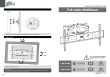
200x200
400x200/400x400
600x400/800x400
/300x300
AS0348T
70kg
(154lbs)
RATED
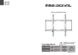
70kg
(154lbs)
RATED
Video Wall Mount
INSTALLATION MANUAL
CAUT IO N: DO NOT EXCEED
RATED LISTED WEIGHT. SERIOUS
INJURY OR PROPERTY DAMAGE
MAY OCCUR!
200x200
400x200/400x400
600x400
/300x300
AS0346T
70"
MAX
9. Lock the Pop-out Module with the Plastic Locking Pieces
Maintenance
• Check that the bracket is secure and safe to use at regular intervals(at least every three months).
• Please contact your distributor if you have any questions.
8. Fixing the Brackets Position with the Antiskid Blocks
Install the both antiskid blocks as close to the adapter brackets as possible.
Tighten screws on the antiskid blocks using a proper screwdriver to prevent display from moving.
D

2
Component Checklist
IMPORTANT: Ensure that you have received all parts according to the component checklist prior to installation.
If any parts are missing or faulty, telephone your local distributor for a replacement.
Package M
Package W
ST6.3x55 (x6)
W-A
concrete anchor
W-B
(x6)
D6 washer (x6)
W-C
1
NOTE: Read the entire instruction manual before you start installation and assembly.
WARNING
M5x14
M-A
(x4) M6x14
M-B
(x4)
washer
M-F
(x4)
M8x20
M-C
(x4)
big
M-H
spacer (x4)
M6x30
M-D
(x4)
M8x30
M-E
(x4) small spacer (x8)
M-G
• Do not begin the installation until you have read and understood all the instructions
and warnings contained in this installation sheet. If you have any questions
regarding any of the instructions or warnings, please contact your local distributor.
• This mounting bracket was designed to be installed and utilised ONLY as
specified in this manual. Improper installation of this product may cause damage
or serious injury.
• This product should only be installed by someone with good mechanical ability
who has basic building experience and fully understands this manual.
• Make sure that the supporting surface will safely support the combined weight of
the equipment and all attached hardware and components.
• Always use an assistant or mechanical lifting equipment to safely lift and position
the equipment.
• Tighten screws firmly, but do not over tighten. Over tightening can cause damage
to the items, This greatly reduces their holding power.
• This product is intended for indoor use only. Using this product outdoors could
lead to product failure and personal injury.
wall plate
A
(x1) pop-out module
B
(x1)
adapter bracket (x2)
C
antiskid block (x2)
D
plastic locking piece (x2)
E

4
3
1. For Solid Brick and Concrete Wall Mounting
Drill pilot holes
2
X X
√
Screw the wall
plate onto
the wall
60mm
(2.4")
60mm
(2.4")
ø 10mm
(ø 3/8")
Mark the
exact location of
mounting holes
1
Installers must verify that the supporting surface will safely support the combined weight of
the equipment and all attached hardware and components.
WARNING
W-C
W-A
W-BW-B
2. For Video Wall Installation (Mounting space as shown below)
3. Installing the Pop-out Module
X
X
Y+5mm
Y+5mm
X=Length of display Y=Height of display
Hang the pop-out module onto the
wall plate. Secure it by tightening
both screws.
Please take off the caps before installation.

4. Installing the Adapter Brackets
65
4-2. For Bump-out or Recessed Back Screens
TV
TV
TV
Tighten all screws but do not over tighten.
· Position the adapter brackets as close as possible to the center of the display.
· Screw the adapter brackets onto the display.
Note: Choose the appropriate screws, washers and spacers (if necessary) according to the type of screen.
or or or
M-C
M-F
M-G
M-C M-D/M-E/
M-F
M-G
M-D/M-E
M-F
M-H
M-D/M-E
M-F
M-G
M-H
TV
TV
TV
4-1 For Flat Back Screens
M-A
M-B
M-C
M-F
5. Hooking the Display onto the Pop-out Module
Note: Before hooking the display, make sure the knobs are rotated to the unlock position.
· Lift the display carefully and hook the display onto the pop-out module. Rotate the knobs to the
lock position to secure the display.
· Use the padlock to prevent the display from being stolen.( Padlock is not included)
Top of the display

8
7
Left
Right
Left
Right
Left
Right
Left
Right
Left
Right
Left
Right
Handles for tilt adjustment.
Screws for micro-adjustment
of up and down.
Knobs for micro-adjustment
of in and out.
6. Adjustment
Push the display to left or right to enable fast alignment.

Left
Right
Left
Right
10
9
Left
Right
Left
Right
wall wall wall
Push the display inward and then release it, the display will be pop-out.
Kickstands provide tilt access for easy cables management and maintenance.
7. Level the Displays
wall
Adjust the display to keep level in vertical and horizontal directions.
3
1
4
2
Note: Install/adjust
the displays by the
numerical order
given.
1.2mm
1.2mm
Note: Use the plastic locking
piece to measure and keep a
1.2 mm gap between displays.
E
/