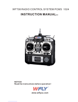
AIRTRONICS RD6000 SPORT User manual
- Category
- Remote controlled toys
- Type
- User manual
This manual is also suitable for

1
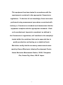
This equipment has been tested in accordance with the
requirements contained in the appropriate Commission
regulations. To the best of our knowledge, these tests were
performed using measurement procedures consistent with
industry or Commission standards and demonstrate that the
equipment complies with the appropriate standards. Each
unit manufactured, imported or marketed, as defined in
the Commission’s regulations, will comform to the sample(s)
tested within the variations that can be expected due to
quality production and testing on a statistical basis.
We further certify that the necessary measurments were
made by Kansai Electronic Industry Development Center,
Ikoma Emission Measrement Station, 10830, Takayama-
Cho, Ikoma-City, Nara, 630-01 Japan.

2
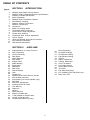
SECTION I INTRODUCTION
RD6000 Super Radio Control System
RD6000 Super Transmitter/Receiver Specifications
Academy of Model Aeronautics
Initial Preparation
RD6000 Super Transmitter Features
NiCd Battery Charging
Airborne System Connections
Airborne Components
Connectors
Audio Low Voltage Alarm
Transmitter Battery Removal
Control Stick Length Adjustment
Throttle High Warning
Transmitter Stick Tension Adjustment
Trainer System
Using the RD6000 Super Micro-Processor
Aero Features Description
Heli Features Description
SECTION II AIRPLANE
Implementation of Control Function
Servo Reversing
Control Centering
Data Reset
Model Selection
Stop Watch
Integral Timer
Model Naming
Exponential
Modulation
Data Copy
Switch Reverse
Click
Throttle Cut
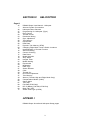
RD6000 Sport Users Manual- Aircraft
Aircraft Menu Structure
Programming for Aircraft (Model Type)
Dual Rate
End Point Adjustments
Landing Gear End Points
Trim Memory
Flaperons
Alarms
Delta (Elevons)
Aileron to Rudder Mix
V-Tail (Rudder to Elevator Mix)
Throttle to Elevator Mix
Compensation Mixers (C-Mix)
TABLE OF CONTENTS
4
4
5
5
6
7
7
8
8
8
9
9
9
10
11
12
13
14
15
15
16
17
18
19
20
21
22
24
25
27
28
29
30
31
32
34
35
36
37
38
40
41
42
43
44
58
Page #
Elev-Flap Mixing
Rud-Aileron Mixing
Rud-Elevator Mixing
Flap-Elevator Mixing
Spoiron
Aileron Differential
Landing Differential
Crow Left Aileron
Crow Right Aileron
Option Menu Screen
Trim Step
Fail Safe (PCM Only)
B-F-S (Battery Fail Safe)PCM Only
Basic ON / OFF
60
61
61
62
62
63
64
65
65
66
67
68
69
69

3
SECTION IV HELICOPTER
RD6000 Super User Manual - Helicopter
Airborne System Connections
Helicopter Menu Structure
Programming for Helicopter (Type)
Pitch Curves
Throttle Curves
Revolution Mixing
Gyro Adjustment
Trim Memory
Exponential
Dual Rate
Dynamic Trim Memory (DTM)
Changing Flight Mode 1 and 2 Switch Locations
Implementation of Control Function
Servo Reversing
Control Centering
Data Reset
Model Selection
Stop Watch
Integral Timer
Model Naming
Exponential
Modulation
Data Copy
Switch Reverse
Click
Throttle Cut
End Point Adjustment
Trim Memory
Alarms ( Throttle High and Flight Mode Only)
Compensation Mixers (C-Mix)
Option Menu
Trim Step
Fail Safe (PCM Only)
B-F-S (Battery Fail Safe) PCM Only
Basic ON / OFF
Swash Plate Type (CCPM)
APPEND I
RD6000 Super Aircraft and Helicopter Setup pages
45
7
46
47
49
52
54
55
56
22
56
57
60
15
15
16
17
18
19
20
21
22
24
25
27
28
29
35
37
40
58
66
67
68
69
69
71
Page #

4
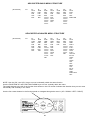
RD6000 Transmitter Specifications:
Transmitter Type:
Dimensions:
Weight:
Power Output:
Frequencies:
Modulation:
Power Supply:
Current Drain:
Temperature Range:
Pulse Width:
Model Memory:
RD6000 Sport Receiver Specifications:
6 Channel, Dual Stick with propriety Microprocessor.
W: 7.5” X H: 8.0” X D: 2.5”
1 lb. 11 oz
600 mWatts
72 MHz
PPM/FM or PPM/FM Reverce
9.6 Volt, 700 mAh NiCd
180 MA
0 to160 degrees F
1.5 ms (nominal)
8
Receiver Type:
Receiver Sensitivity:
Dimensions:
Weight:
Receiver Power Supply:
92777Z PPM/FM 7 Channel, Super Narrow Band with Universal “Z” Connectors
1.5 microvolts
L: 2.25”, W: 0.6”, H: 0.82”
1.2 ounces
Four Cell, 4.8 Volt, 700 mAh NiCd
The following additional receivers are compatable if part number 99399Z Adaptor is used.
92745 PPM/FM 4 Channel, Micro Super Narrow Band Receiver
92765 PPM/FM 6 Channel, Super Narrow Band Receiver
RD6000 SPORT RADIO CONTROL SYSTEM
Thank you for selecting the Airtronics RD6000 Super Radio System. In designing the RD6000 Super we
have made every effort to provide you with a radio that will allow you to extract the maximum performance
from your powered aircraft, sailplane, or helicopter, while at the same time simplifying the task of setting up
and adjusting your model. These instructions are written in great detail to help you understand what all of
you RD6000 Super capabilities are. Because of the many features of the RD6000 Super, this manual is
quite long. Don’t be intimidated! To actually use the system, you may only need to read the INTRODUC-
TION section, the Common Functions section, and study the section that applies to your type of aircraft.
Each type of aircraft, i.e., fixed wing and helicopter has its own self-contained section describing each
applicable feature and its implementation. However, helicopter flyers may find it advantages to read all
sections of the manual to become more acquainted with the operation of the RD6000 Super unit. Note that
the labels for fixed wing switch functions are in red letters and helicopter switch functions are in white
letters.
Again, we appreciate your selection of an Airtronics Radio Control System and wish you many hours of
flying enjoyment.
SECTION I

5
ACADEMY OF MODEL AERONAUTICS
5151 East Memorial Drive
Muncie, Indiana 47302
The Academy of Model Aeronautics (AMA) is a national organization representing modelers in the United States. We
urge you to examine the benefits of membership, including liability protection in the event of certain injuries. The
Academy has adopted simple and sane rules which are especially pertinent for radio controlled flight as the OFFICIAL
AMA NATIONAL MODEL AIRCRAFT SAFETY CODE, which we have partially reprinted below:
I will not fly my model aircraft in sanctioned events, airshows or model flying demonstrations until it has been proven
to be airworthy by having been previously, successfully flight tested.
I will not fly my model higher than approximately 400 feet within 3 miles of an airport without notifying the airport
operator. I will give the right-of-way and avoid flying in the proximity of full-scale aircraft. Where necessary, an
observer shall be utilized to supervise flying to avoid having models fly in the proximity of full-scale aircraft.
Where established, I will abide by the safety rules for the flying site I use, and I will not willfully and deliberately fly my
models in a careless, reckless and/or dangerous manner.
I will have completed a successful radio equipment ground range check before the first flight of a new or repaired
model.
I will not fly my model aircraft in the presence of spectators until I become a qualified flyer, unless assisted by and
experienced helper.
I will perform my initial turn after take off away from the pit or spectator areas, unless beyond my control.
I will operate my model using only radio control frequencies currently allowed by the Federal Communications
Commission. (See chart below) Only properly licensed amateurs are authorized to operate equipment on amateur
band frequencies.
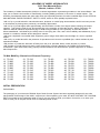
72 MHz BAND by Channel and Channel Frequency
11 72.010
12 72.030
13 72.050
14 72.070
15 72.090
16 72.110
17 72.130
18 72.150
19 72.170
20 72.190
21 72.210
22 72.230
23 72.250
24 72.270
25 72.290
26 72.310
27 72.330
28 72.350
29 72.370
30 72.390
31 72.410
32 72.430
33 72.450
34 72.470
35 72.490
36 72.510
37 72.530
38 72.550
39 72.570
40 72.590
41 72.610
42 72.630
43 72.650
44 72.670
45 72.690
46 72.710
47 72.730
48 72.750
49 72.770
50 72.790
51 72.810
52 72.830
53 72.850
54 72.870
55 72.890
56 72.910
57 72.930
58 72.950
59 72.970
60 72.990
INITIAL PREPARATION
PACKAGING:
The packaging of your Airtronics RD6000 Super Radio Control System has been especially designed for the safe
transportation and storage of the radio’s components. After unpacking your radio, DO NOT DISCARD THE CONTAIN-
ERS! You should set the packaging aside for use if you ever need to send your radio in for service, or to store your
radio in case you do not plan to use it for an extended period of time.

6
RD6000 SUPER TRANSMITTERS FEATURES
The RD6000 Super narrow band PPM/FM computer radio control system is designed for the use by power model,
sailplane, and helicopter pilots who demand a quality product. The RD6000 Super is packed with all of the capabilities
that the beginner as well as the more advanced modelers demand for all three types of flying. It has the features
available to get the most out of any type of model.
Program Features for all types of models (BASIC turned ON)
8 Model Memory
Stop Watch
Digital Trims
Servo Reversing on all channels
Dual Rate on Elevator and Aileron channels
(Plus Rudder on Helicopter)
Large Screen Liquid Display (LCD)
End Point Adjustment on all channels
Aircraft Advanced Features (BASIC turned OFF)
All of the features listed under the program with the BASIC turned ON are also included in this Advanced Features
section.
Expoential Aileron Differential
Trim Memeoy Landing Differential
Trim Authority (STEP) for digital trims Crow
Model Naming (3 Letters) Dual Rate Alarm
Failsafe / Hold (PCM Rx only) Menu Options
Receiver Battery Failsafe (PCM Rx only) Flap to Elevator Mix
Low Battery Alarm Throttle to Elevator Mix
Integtal System Timer Rudder to Aileron Mix
Data Copy Aileron to Rudder Mix
Flaperon Mix Rudder to Elevator Mix
Spoiron Mix Elevator to Flap Mix
Elevon Mix Switch Reverse
V-Tail Mix 2 Comensation Mixers
Throttle Cut 4 Modulation Modes
Click Delta Mix
Helicoter Features (BASIC) Helicopter Features (Advanced) includes Basic
Stop Watch Exponential
Servo Reversing Fail Safe (PCM Rx Only)
Dual Rate Elev, Ail and Rud Throttle Cut
Servo Centering Model Naming (3 Letters)
End Point Adjustment 2 C-Mixers
Throttle Curve (5 Point) in all Flight modes Integral System Timer
Revo Mix (3 Point) in all Flight Modes Trim Step
4 Flight Modes Switch Reversing
Gyro Senseativaty Adjustment in all Flight Modes Data Copy
Pitch Curve (5 Point) in all Flight Modes 4 Modulation Modes
Model Select Click
Model Type Battery Fail Safe (PCM Rx only)
Data Reset Dynamic Trim Memory
Bacic ON Swash Plate Type
Basic OFF
Option Menu
Model Type selection
Center Adjustment on EL, AL, TH, RU, and P-F
Data Reset
LCD Transmitter Voltage Meter
High Capacity Transmitter/Receiver NiCd
Batteries
Adjustable Stick Tension and Length
Low Battery, High Throttle and Power Alarms

7
7/B
6
5
4
3
2
1
92777/72 FM
B
A
N
D
Dual Conversion
BY
Narrow Band Receiver
24
NiCd
Battery
Switch Harness
Charge
Connector
92777 Receiver
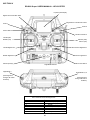
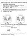
AERO HELI
Flap
Retract Gear
Rudder
Throttle
Aileron
Elevator
Collective Pitch
Gyro
Rudder
(Tail Rotor)
Throttle
Aileron
(L/R Cyclic)
Elevator
(F/A Cyclic)
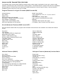
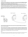
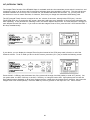
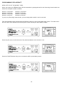
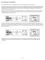
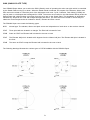
The above diagram shows how to connect the components of your RD6000 Sport system together. At this point your
objective is to get the system operating on your workbench. Once connected you must then refer to the corresponding
diagram for your system, i.e., either AERO or HELI showing the transmitter control stick function.
NiCd BATTERY CHARGING INFORMATION:
In order to protect the charging circuit in your RD6000 Super transmitter, a diode has been installed to protect it from
some of the high discharge rate “cycler’s” on the market. We recommend that you charge the transmitter battery
(while installed) with the supplied ATX charger, Part # 95033.
Should you wish to “cycle” or discharge the transmitter battery, you must first remove it from the transmitter. This
allows you to bypass the protective diode.
The following two Airtronics service items will allow you to “cycle” your RD6000 Super transmitter battery. See your
local dealer for these items.
(1) #99704 Transmitter Charging Plug with Cable for use with your cycling device (black wire w/white tracer is
positive.
(1) #97051 Transmitter Battery Cycling Adapter Cable.
Above items will also work with Airtronics Quasar, Radiant, and Vanguard transmitter batteries. Airtronics does NOT
recommend the use of any fast or quick chargers.
AIRBORNE SYSTEM CONNECTIONS

8
AIRBORNE COMPONENTS
While your systems batteries are charging, you can familiarize yourself with the airborne portion of your radio. The
airborne portion of the radio refers to any components which are mounted in your plane or helicopter and carried aloft
when you fly. The airborne components consist of the receiver, which receives the signals from the transmitter,
decodes them, and relays the commands to the servos; the servos which are simply electronically controlled motors
used to move the controls of the plane; the NiCd battery pack which provides power for the receiver and servos to
operate; and the switch harness which allows you to turn the airborne package on and off.
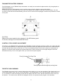
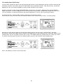
CONNECTORS
Your RD6000 Super unit is equipped the new universal AIRTRONICS “Z” connectors which are color coded blue, and
are electrically compatible with the receivers of other radio control system manufacturers. The connectors are rugged
but should be handled with care. Note that these connectors are not compatible with older AIRTRONICS R/C
equipment unless Adapter p/n 99399Z is used!
“Z” CONNECTOR
(-)Negative
(+)Positive
Signal
AUDIO LOW VOLTAGE ALARM
Your RD6000 Super transmitter is equipped with an Audio Alarm which will sound whenever the transmitter batteries
drop below 9.5 volts during transmitter operation. If the alarm sounds while you are flying, land immediately and
don’t operate the transmitter until it has been charged for 12 hours. The transmitter should normally operate 120 to
150 minutes before the alarm sounds. If the alarm sounds even after the batteries have been on charge for the
required time it indicates that there is a problem with either the battery pack or the transmitter, and you should contact
AIRTRONICS about service.

9
TRANSMITTER BATTERY REMOVAL
The NiCd battery in your RD6000 Super transmitter can easily be removed and replaced with a fully charged pack to
extend operating time.
Additional packs are sold separately as an accessory item under the Airtronics part number 95010.
To remove the pack, push down on the two ears of the battery door located on the rear of the transmitter. The door
can then be removed and the NiCd battery pack can now be removed and unplugged. Reverse the procedure to install
a new pack.
CAUTION:
Observe the correct polarity when plugging in the NiCd battery pack.
If incorrect, damage to the transmitter will occur!
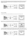
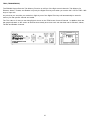
CONTROL STICK LENGTH ADJUSTMENT
The sticks in your RD6000 Super transmitter are adjustable in length and spring tension to allow you to tailor their feel
to your personal preference. To adjust stick length, hold Part B with your fingers and unscrew Part A counterclockwise
to loosen the two pieces. Now screw Part A in or out to the desired position and lock it in place by screwing Part B
against it. It is best to leave at least four threads inside Part A when screwed out to its longest length for the best
mechanical security. Do not over tighten when you screw the two parts together.
THROTTLE HIGH WARNING
The RD6000 Super has a built in warning feature that will not allow you to use the transmitter if the throttle stick is not
in the lowest position when you turn on the transmitter. If the throttle stick is not in the low position, when you turn it
on, you will hear a continuous beeping sound and the display will read TH-HI! Pull the throttle stick down to the full
low position. The normal menu will then be displayed and you can operate and/or program the transmitter.
Part (A) Loosen End Cap First
Part (B) Adjust Stick Length by turning here

10
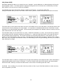
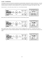
TRANSMITTER STICK TENSION ADJUSTMENT
To adjust the spring tension of the transmitter sticks you need to remove the back of the transmitter case. First
remove the antenna and the NiCd battery pack from the transmitter. Now remove the eight screws that hold the case
back in place, four in the main case, two in the LCD back cover and two on the handle.
Once the screws are removed swing the back of the case away from the transmitter being careful of the trainer plug
wiring.
There are four locations for the stick tension adjustment screws installed because the stick controlling the throttle is
reattached and has no tension adjustment. The #1 and #3 screws adjust the tension for the vertical motion of each
stick. The #2 and #4 screws adjust the tension for the horizontal motion of each stick. To make the tension adjustment
use a small phillips type screwdriver to turn the adjustment screws. Turning the screw clockwise will increase the stick
tension, turning it counterclockwise will decrease the tension. Once you have completed your stick adjustments,
replace the case back and install the NiCd battery pack and antenna. Be careful to line the battery charging port pins
when replacing the back cover.
WARNING:
Any other modifications made to the transmitter other than adjusting stick tension will void any and all warranties
covered be Airtronics Inc.
Screw Locations
1
2
3
4

11
TRAINER SYSTEM
The Trainer system in the RD6000 Super transmitter allows you to connect any two Airtronics RD6000 Super together
for the purpose of training a new pilot. You can also connect the RD6000 Super to either an RD6000 Super, RD6000,
RD6000 Sport, VG 400, VG 600, Radiant or Vanguard PPM unit. The Trainer cord to use is the ATX Part # 97100.
The RD6000 Super is NOT compatible with Infinity 660 or Quasar units.
In actual use, one of the two transmitters will serve as the Master and the second transmitter will serve as the Trainer.
The Master transmitter is held by the instructing pilot, AND IS THE TRANSMITTER THAT MUST MATCH THE
RECEIVER FREQUENCY INSTALLED IN THE MODEL! The trainer transmitter is held by the learning pilot, and does
not need to be on the same frequency as the model. The frequency of the Trainer transmitter is unimportant because
the switch of the trainer transmitter is
NOT turned on during instructional flying. Normally during training, the
instructor takes the model off and flies it to a reasonable altitude. While the Master/Trainer switch on the Instructors
transmitter is left in its OFF position, the Master transmitter will have full control of the model. When the instructor is
ready to begin training, he presses and holds the spring loaded switch on his transmitter which transfers control to the
student.
(As long as the instructor holds his Trainer switch in the ON position, the model will respond to the commands of the
Trainer transmitter sticks allowing the pupil to fly the model. It is not necessary for the student to hold the trainer
switch on the Trainer transmitter.)
When the instructor ceases to stop training, or if he feels that the student is in a situation that endangers the model, the
instructor can release the spring loaded switch and control of the model will immediately return to the Master transmitter.
To use the Trainer system, you must plug the appropriate Trainer cable into the back of both the Master and the Trainer
transmitters. Turn on the Master transmitter and the Model. The cable will energize the encoder section of the Trainer
transmitter. Once you have verified that both the Master and the Trainer transmitters will control the model when the
spring loaded switch in the appropriate position you are ready to start training.
NOTE:
Both transmitters must be programmed identically for the trainer system to function properly. All servos must operate in
the same direction, centering, end points, and other settings such as type of Modulation must be identical.
Trainer Switch
(Spring Loaded)
Master Transmitter
Trainer Transmitter

12
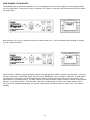
USING THE RD6000 Super MICROPROCESSOR
Airtronics has invested a large amount of design effort to ensure that the powerful capabilities of the RD6000 Super
are as simple as possible to use. This manual has been written to offer the user complete instructions for either fixed
wing aircraft or helicopter models. The manual is divided into three sections. One for introduction and another for
aircraft (both powered and sailplane), and one for helicopters. You only need to read the introduction section and the
one that applies to your type of model. In most cases all of the programming of a setup is accomplished through the
use of the input keys on the RD6000 Super transmitter. The function(s) of these are shown below.
Note: Pressing the INC+/YES and DEC-/NO keys simultaneously will clear a setting and return it to the default value.
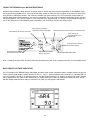
BAR GRAPH VOLTAGE INDICATOR
As a convenience the RD6000 Super transmitter provides a Bar Graph transmitter battery voltage indicator at the top
of the Liquid Crystal Display screen labeled “E” and “F”. The “F” symbol indicates FULL and the “E” indicates EMPTY.
You can consider it similar to a visible gas gauge. The Bar Graph indicator is in addition to the normal battery voltage
that is displayed on the main screen when ever you select either AIR or HELI by pushing the END key twice. When
the Bar Graph reads less than half you should not fly until you recharge the transmitter.
Press this key to move up in a menu
Press this key to increase a value or to indicate YES
Press this key to
decrease a value or to
indicate NO
Press this key to return to
the previous screen
Select Flight Mode (Helicopter)
Press this key to move
down in the menu
Press this key to select a
channel and move to the left
Press this key to select a
channel and move to the Right

13
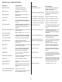
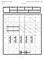
RD6000 Super AERO FEATURES
FEATURES
STW (Stopwatch)
REV (Reverse)
D/R (Dual Rate)
CNT (Center)
TRM (Trim)
EXP (Exponential)
EPA (End Point Adjustment)
M-SL (Model Select)
MOD (Modulation)
TYP (Type of Model)
INT (Integral Timer)
RST (Reset)
CLK (Click)
NAM (Name)
SW-R (Switch Reverse)
CPY (Copy)
FLAPE (Flaperons)
DELTA (Elevons)
V-TAIL (Rudder and Elevator)
D/A-A (Dual Rate Alarm)
DESCRIPTION
Used as a stopwatch or to
countdown to a preset time.
Reverses the servo operating
direction.
Adjusts servo throw. Available on
Elev and Ail.
Changes servo neutral position.
The LCD provides an indicator of
the value, as well as the direction of
the trim.
Changes the linear movement of the
servo to the relation of the stick
movement. Can be set Positive or
Negative.
Limits the total movement of a servo
in each direction.
Select models 1, 2, 3, 4, 5, 6, 7, 8.
Transmitting Modulation PPM/FM,
PPM/Reverse FM, PCM1, PCM2.
Model Type Aircraft or Helicopter.
Used to show how long the
transmitter has been in use. Can be
reset to zero.
Clears all setup data in any model to
factory default settings.
A beep sound can be heard every
time you press a transmitter key.
Options Active or Inoperative.
You can use up to 3 characters to
name your model.
You can reverse to default direction
of all control switches.
Copy one model to another.
Activates 2 channels to be used for
Ailerons.
Ailerons operate as ailerons and as
well as Elevators. Used for flying
wings.
Used for V-Tail models.
Alerts you when a Dual Rate switch
is on. Options On or Off.
T-CUT (Throttle Cut)
C-MIX (Compensation Mixing)
E>F (Elevator to Flap Mixing)
R>A (Rudder to Aileron Mixing)
R>E (Ruder to Elevator Mixing)
F>E (Flap to Elevator Mixing)
SPOIR (Spoilerons)
AI-DIF (Aileron Differential)
L-DIF (Landing Differential)
CR:LA (Crow Left Aileron)
CR:RA (Crow Right Aileron)
OPT (Option Menu)
Step (Trim Step)
FAIL (Fail Safe)
B-F-S ( Battery Fail Safe)
BASIC ( ON/OFF )
You can set the point where the
throttle can be cut using the
throttle cut-off button.
Ability to mix a master channel to
another slave channel with a C-
Mix Switch.
Ability to mix Elevator to Flap.
Ability to mix Rudder to Ailerons.
Ability to mix Ruder to Elevator.
Ability to mix Flap to Elevator.
For sailplanes. Both aileron will act
as spoilers as the throttle stick is
used.
Changes the total amount of throw
up and down to both aileron
servos independently to help stop
a bad yaw.
Allows Aileron control to remain
effective when Crow or Spoilers
are used (Sailplane)
Crow is used to slow the sailplane
down. Ailerons go up when flaps
go down. Lt and
Right Ailerons are adjustable
Advanced program allows you to
turn off or on function displays.
Sets the amount of movement a
servo will move with one beep of
the trim.
You can preset a default control
input when aircraft loses it’s signal
from the transmitter. Only works
with a PCM receiver.
Will bring the throttle servo to idle
when the airborne battery reaches
a predetermaned low voltage. Only
works with a PCM receiver.
Turn Basic menu on or off
FEATURES DESCRIPTION

14
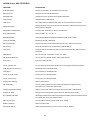
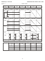
RD6000 Super HELI FEATURES
FEATURES
STW (Stopwatch)
REV (Reverse)
D/R (Dual Rate)
CNT (Center)
TRM (Trim)
EXP (Exponential)
EPA (End Point Adjustment)
M-SL (Model Select)
MOD (Modulation)
TYP (Type of Model)
INT (Integral Timer)
RST (Reset)
CLK (Click)
NAM (Name)
SW-R (Switch Reverse)
CPY (Copy)
T-CUT (Throttle Cut)
DTM (Dynamic Trim Memory)
GYR (Gyro)
CV-P# (Throttle Curve)
CV-P# (Pitch Curve)
RV (Revolution Mixing)
FAIL (Fail Safe)
C-MIX (Compensation Mixing)
STEP (Trim Step)
B-F-S (Battery Fail Safe)
SWH (Cyclic Type)
BASIC ( ON/OFF)
OPT (Option Menu)
DESCRIPTION
Used as a stopwatch or to countdown to a preset time.
Reverses the servo operating direction.
Adjusts servo throw. On Elev, Ail and (Rud in Heli Mode)
Changes servo neutral position.
The LCD provides an indicator of the value, as well as the direction of the trim.
Changes the linear movement of the servo to the relation of the stick movement. Can
be set Positive or Negative.
Limits the total movement of a servo in each direction.
Select models 1, 2, 3, 4, 5, 6, 7, 8.
Transmitting Modulation PPM/FM, PPM/Reverse FM, PCM1, PCM2.
Model Type Aircraft or Helicopter.
Used to show how long the transmitter has been in use. Can be reset to zero.
Clears all setup data in any model to factory default settings.
A beep sound can be heard every time you press a transmitter key. Options Active or
Inoperative.
You can use up to 3 characters to name your model.
You can reverse to default direction of all control switches.
Copy one model to another.
You can set the point where the throttle can be cut using the throttle cut off button.
Memorizes trims in each flight mode.
Gyro sensitivity for each flight mode
To setup a curve in all flight modes.
To setup a curve in all flight modes.
Tail rotor offset mixing
You can preset a default control input when aircraft loses it’s signal from the
transmitter. Only works with a PCM receiver.
Ability to mix a master channel to another slave channel with a C-MIX switch.
Sets the amount of movement a servo will move with one beep of the trim.
Will bring the throttle servo to idle when the airborne battery reaches a predetermaned
low voltage. Only works with a PCM receiver.
5 Cyclic Options (Normal, CP3F, CP3B, CP4F, CP4B)
Basic menu ON or Off
Advanced program allows you to turn off or on function displays.

15
SECTION II COMMON FUNCTIONS
The following functions are common and are applicable to both Aircraft and Helicopter sections of this manual. The
Liquid Crystal Display shows an Aero model selected; however, a similar screen will be displayed when a Helicopter
type model is selected.
NOTE: Switches labeled with red lettering are for aircraft and white lettering is used for helicopter.
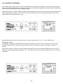
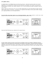
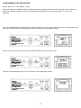
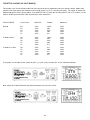
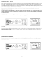
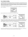
IMPLEMENTATION OF CONTROL FUNCTIONS
In this section you will learn how to implement the control functions and tailor the servo movement and centering for
each control. Pressing the END key on the front panel several times will bring you to the following screen, i.e., the
initial screen that indicates the current model type and number, PPM modulation and the transmitter NiCd battery
pack voltage.
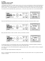
Press the (CH +) key to obtain the STW screen. The Elevator channel will appear on the upper part of the screen. The
model number and aero will be present on the left side and the stop watch will indicate zero since no time has been
programmed.
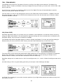
REV (SERVO REVERSING)
The RD6000 Super allows you to electronically REVERSE the direction of rotation for each of the servos in use. This
allows you to hook up your control linkages and pushrods in the most mechanically desirable manner without regard
to the direction of servo movement. After installing your linkages check to see if any of the controls move in the wrong
direction when you move the controls. If so proceed as follows for reversing the elevator channel. Reverse for all other
channels are done the same way.
Press the FUNCTION down key to arrive at the following screen:
If the Elevator servo moves in the wrong direction, press the INC +/YES key. To move to the Elevator D/R (Dual Rate)
screen, press the FUNCTION down key.

16
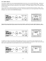
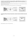
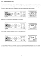
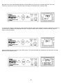
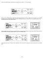
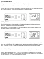
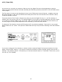
CNT (CONTROL CENTERING)
Your RD6000 Super allows you to fine-tune the CENTER or neutral position of all flight control servos. After hooking
up your controls and mechanically centering all linkages to the approximate positions, press the FUNCTION down key
to arrive at the following screen for the Elevator control.
(Note that the Aileron, Throttle, Rudder and Flap centering operates in the same manner when you select that channel
on the upper part of the screen. You can move across to the CNT function of each channel as well as some of the
other functions by pressing the (CH+ ) key.
By pressing the INC+/YES or DEC-/NO keys you can vary the value from 0 to + or - 100%. Default is 0%
IMPORTANT NOTE:
It is desirable to adjust the control linkages as close as possible to the correct center positions, then use the CNT
(CENTER) commands to “Fine-tune” the exact position of the control surface when the transmitter control is in
neutral.
Using a large amount of electronic centering adjustments will decrease the total throw available for that channel. In
particular, centering adjustments greater than + or - 50% will tend to make the extreme stick position on one end less
responsive!

17
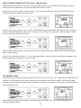
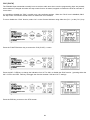
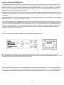
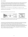
If you want to “UNDO” all of your programmed parameters at one time, you can use the RST function. However, be
certain that is what you want to do, since this function will reset all settings to the factory default settings. The RST
function will only affect the specific model that you have selected. ALL OTHER Models in memory are unaffected by
the RST function.
Press the END key to select the initial AR 1 screen that indicates the Transmitter NiCd pack battery voltage. Now,
press the CH + to access the STW (Stopwatch) screen. This screen allows you to move up and down as well as left
and right on the screen in the RD-6000 Super program.
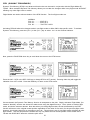
RST (DATA RESET)
To RESET ALL DATA for this model to default settings press the (CH +) key and the screen will flash YES. Now,
press the INC +/YES key and the screen will indicate OK! All paramameters on this specific model number have now
been reset to default values. Press the END key twice to return to the STW screen.
Press the CH + key several times to move across the CH indicator portion of the screen until it reads “etc”. Now,
press the FUNCTION down key three times to move down in the menu until you reach the RST (Data Reset) screen.
i

18
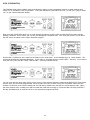
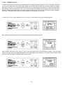
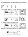
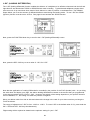
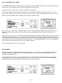
TYP (MODEL TYPE)
To select the type of model you wish to program, press the (CH+) key to scroll to “etc”. Next press the FUNCTION key
to select TYP. Now press the (CH+) key to select the next model type, either HELI or AERO. THe screen will flash
YES with the type of model indicated on the LCD display. To confirm your selection, press the INC+/YES key and the
screen will indicate OK!
Press the END key three times to return to the inital screen that will then show your model number/type and
transmitter battery voltage.
HOW TO SELECT MODEL SET-UPS: M-SL (Model Select)
The RD6000 Super has built in memory to store four model setups in any combination of model types. To use or
modify one of the model setups you first must select M-SL in the etc menu.
Assume that you want to select a second model. To do so, press the END key to bring up the initial screen that
indicates transmitter voltage and model number.
Press the (CH +) key to scroll to “etc”. Use the FUNCTION down key to select MSL. Next press the INC +/YES key
and the screen will flash MSL to indicate you can select a second model. Press the INC +/YES key again to select
the next or following model such as AR2.
Press the END key three times to return to the initial screen which will show the model number and the transmitter
battery voltage reading.
NOTE: if the model type is incorrect, i.e., HELI rather than AERO, continue with the model selection procedure. The
model type can then be selected on the TYP screen.

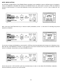
19
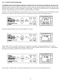
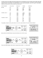
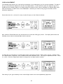
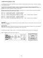
STW (STOPWATCH)
The RD6000 Super offers a built-in timer and allows the pilot to use the stopwatch function in either elapsed time
mode or in a countdown mode of operation. To use the stopwatch, press either the (CH -) or the (CH +) key to select
“etc” on the Channel indicator display.
Now press the FUNCTION down key to scroll through the various screen’s until you find the STW screen with the
flashing >indicator. This is where you can set your stopwatch countdown time. The STW (set) screen is just above
the INT screen as shown on the Menu Structure, page 31.
Use the INC +/YES key to set a value for the Start of your count down; as an example set it at 10.00 minutes. The
screen will look like the following illustration. If you want to decrease the time, use the DEC - /NO key. If you want to
clear the time, press the INC +/YES and the DEC - /NO keys simultaneously.
You can now start the stop watch when you are on any of the channel indicator screens that displays the STW screen
and the time you previously programmed. Press the INC+/YES key to start or stop the countdown. When the time
reaches 10 seconds, a tone will be heard and one will also be heard every second as it counts down to zero. When
the timer reaches zero, a steady tone will be heard and it will start counting up. Press the INC+/YES key and DEC-/
NO key simultaneously to reset the timer to your previously programmed time.
etc
etc
etc

20
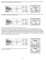
INT (INTEGRAL TIMER)
The Integral Timer function of the RD6000 Super is activated each time the transmitter power switch is turned on, and
continues to time up to 99 hours and 59 seconds at all times when the transmitter is turned on. This time will give an
excellent indication of how many hours of actual use you RD6000 transmitter has accrued. Or, you may wish to re-
set the timer to zero at certain intervals, for instance, each time you charge the transmitter NiCd battery pack.
The INT (Integral Timer) function is located in the “etc” column of the menu, directly below STW (set). Use the
FUNCTION down key to access the INT screen. Note that it will have some indication of how long the transmitter has
been operating. It may look like the following screen, but with a different time shown. The time will show a change for
each elapsed second and minute. If you want to reset the Integral Timer to Zero, press the INC +/YES and the DEC -/
NO keys simultaneously.
If you desire, you can display the Integral Timer function instead of the STW (stop watch) function on all of the
Channel screens. To do so while you are in the INT screen, press the (CH +) key to obtain the following screen.
Press the INC +/YES key and the bottom line of the screen will change from INH (inhibit) to read ACT (active). You
can press either the DEC -/NO key or the INC +/YES key to change it back to INH. Most pilots prefer to have the
Stop watch function displayed on all of their Channel screens, rather than the Integral Timer, therefore, they leave the
Integral Timer DSP at INH (inhibit). Press the END key twice to get back to the top of the “etc” menu column.
Page is loading ...
Page is loading ...
Page is loading ...
Page is loading ...
Page is loading ...
Page is loading ...
Page is loading ...
Page is loading ...
Page is loading ...
Page is loading ...
Page is loading ...
Page is loading ...
Page is loading ...
Page is loading ...
Page is loading ...
Page is loading ...
Page is loading ...
Page is loading ...
Page is loading ...
Page is loading ...
Page is loading ...
Page is loading ...
Page is loading ...
Page is loading ...
Page is loading ...
Page is loading ...
Page is loading ...
Page is loading ...
Page is loading ...
Page is loading ...
Page is loading ...
Page is loading ...
Page is loading ...
Page is loading ...
Page is loading ...
Page is loading ...
Page is loading ...
Page is loading ...
Page is loading ...
Page is loading ...
Page is loading ...
Page is loading ...
Page is loading ...
Page is loading ...
Page is loading ...
Page is loading ...
Page is loading ...
Page is loading ...
Page is loading ...
Page is loading ...
Page is loading ...
Page is loading ...
Page is loading ...
Page is loading ...
Page is loading ...
-
 1
1
-
 2
2
-
 3
3
-
 4
4
-
 5
5
-
 6
6
-
 7
7
-
 8
8
-
 9
9
-
 10
10
-
 11
11
-
 12
12
-
 13
13
-
 14
14
-
 15
15
-
 16
16
-
 17
17
-
 18
18
-
 19
19
-
 20
20
-
 21
21
-
 22
22
-
 23
23
-
 24
24
-
 25
25
-
 26
26
-
 27
27
-
 28
28
-
 29
29
-
 30
30
-
 31
31
-
 32
32
-
 33
33
-
 34
34
-
 35
35
-
 36
36
-
 37
37
-
 38
38
-
 39
39
-
 40
40
-
 41
41
-
 42
42
-
 43
43
-
 44
44
-
 45
45
-
 46
46
-
 47
47
-
 48
48
-
 49
49
-
 50
50
-
 51
51
-
 52
52
-
 53
53
-
 54
54
-
 55
55
-
 56
56
-
 57
57
-
 58
58
-
 59
59
-
 60
60
-
 61
61
-
 62
62
-
 63
63
-
 64
64
-
 65
65
-
 66
66
-
 67
67
-
 68
68
-
 69
69
-
 70
70
-
 71
71
-
 72
72
-
 73
73
-
 74
74
-
 75
75


AIRTRONICS RD6000 SPORT User manual
- Category
- Remote controlled toys
- Type
- User manual
- This manual is also suitable for
Ask a question and I''ll find the answer in the document
Finding information in a document is now easier with AI
Related papers
-
AIRTRONICS RD6000 SPORT Owner's manual
-
-
-
-
-
-
-
-
-