Page is loading ...

Series CN7200, CN7600, CN7800, CN7500
Microprocessor Based Temperature Process Control
Specifications - Installation and Operating Instructions
Bulletin E-90-OCN
OMEGA ENGINEERING, INC.
1 - 888 - TC - OMEGA USA & Canada
1 - 203 - 359 - 1660 INTERNATIONAL
E-90-OCN:Layout 1 8/31/10 3:05 PM Page 1

Series CN7200, CN7600, CN7800, CN7500
Microprocessor Based Temperature Process Control
Specifications - Installation and Operating Instructions
Bulletin E-90-OCN
OMEGA ENGINEERING, INC.
1 - 888 - TC - OMEGA USA & Canada
1 - 203 - 359 - 1660 INTERNATIONAL
E-90-OCN:Layout 1 8/31/10 3:05 PM Page 1

Page 2
TABLE OF CONTENTS
Model Number Identification . . . . . . . . . . . . . . . . . . . . . . . . . . . . . . . . . . . . 3
Getting Started . . . . . . . . . . . . . . . . . . . . . . . . . . . . . . . . . . . . . . . . . . . . . . 3
Installation. . . . . . . . . . . . . . . . . . . . . . . . . . . . . . . . . . . . . . . . . . . . . . . . . . 4
Panel Cutout Dimensions . . . . . . . . . . . . . . . . . . . . . . . . . . . . . . . . . . . . . . . . . . 4
Mounting . . . . . . . . . . . . . . . . . . . . . . . . . . . . . . . . . . . . . . . . . . . . . . 5
Wiring Diagrams . . . . . . . . . . . . . . . . . . . . . . . . . . . . . . . . . . . . . . . . . . . . . . . 6-7
Front Panel Key Functions . . . . . . . . . . . . . . . . . . . . . . . . . . . . . . . . . . . . . 8
Security Features . . . . . . . . . . . . . . . . . . . . . . . . . . . . . . . . . . . . . . . . . . . . 8
Control Operation Description . . . . . . . . . . . . . . . . . . . . . . . . . . . . . . . . 9-10
Programming and Operation for Ramp and Soak Feature . . . . . . . . . . 11-13
Programming and Operation for PID Function. . . . . . . . . . . . . . . . . . . . . . 14
Description of Menu Structure . . . . . . . . . . . . . . . . . . . . . . . . . . . . . . . . . 15
Operation Menu. . . . . . . . . . . . . . . . . . . . . . . . . . . . . . . . . . . . . . . . . . 15-16
Regulation Menu . . . . . . . . . . . . . . . . . . . . . . . . . . . . . . . . . . . . . . . . . 17-19
Initial Setting Menu . . . . . . . . . . . . . . . . . . . . . . . . . . . . . . . . . . . . . . . 20-22
Alarm Output Description . . . . . . . . . . . . . . . . . . . . . . . . . . . . . . . . . . . . . 23
Communication Register List. . . . . . . . . . . . . . . . . . . . . . . . . . . . . . . . 24-25
Diagnostic Error Messages . . . . . . . . . . . . . . . . . . . . . . . . . . . . . . . . . . . . 26
Specifications . . . . . . . . . . . . . . . . . . . . . . . . . . . . . . . . . . . . . . . . . . . . . . 29
Input Sensor Ranges . . . . . . . . . . . . . . . . . . . . . . . . . . . . . . . . . . . . . . . . 30
Precautions. . . . . . . . . . . . . . . . . . . . . . . . . . . . . . . . . . . . . . . . . . . . . . . . 31
E-90-OCN:Layout 1 8/31/10 3:05 PM Page 2

Page 3
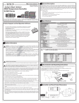
MODEL NUMBER IDENTIFICATION
GETTING STARTED
1. Install the control as described on page 4.
2. Wire your control following the instructions on pages 6-7. Please read the
Precautions section located at the end of this manual before wiring the control.
3. For best results when programming changes are necessary, make all changes
to the Initial Setting mode (Pages 20-22) before making changes to the
Regulation Mode (Pages 17-19) or Operation Mode (Pages 15-16). If any error
messages occur, check the Diagnostic Error Message Section (Page 26) for
assistance.
CN75
OUTPUT 2
3 = Relay
OUTPUT 1
2 = Voltage Pulse
3 = Relay
5 = Current
CN78
OUTPUT 2
3 = Relay
OUTPUT 1
2 = Voltage Pulse
3 = Relay
5 = Current
CN76
OUTPUT 2
3 = Relay
OUTPUT 1
2 = Voltage Pulse
3 = Relay
5 = Current
6 = Linear Voltage
CN72
OUTPUT 2
3 = Relay
OUTPUT 1
2 = Voltage Pulse
3 = Relay
5 = Current
6 = Linear Voltage
E-90-OCN:Layout 1 8/31/10 3:05 PM Page 3

Page 4
INSTALLATION
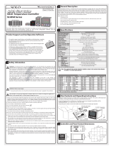
Mount the instrument in a location that will not be subject to excessive temperature,
shock, or vibration. All models are designed for mounting in an enclosed panel.
Select the position desired for the instrument on the panel. Prepare the panel by
cutting and deburring the required opening per the panel cut out dimensions listed
below. Follow the mounting instructions listed on page 5. Lastly, wire the controller
per the appropriate wiring diagram listed on page 6.
PANEL CUTOUT DIMENSIONS
E-90-OCN:Layout 1 8/31/10 3:05 PM Page 4

Page 5
MOUNTING METHOD
Step 1: From the front of the panel, slide the controller housing through
the cut out. The housing gasket should be against the housing
flange before installing.
Step 2: Insert the mounting brackets into the mounting grooves on the
top and bottom of the controller (CN78, CN76, and CN72). For the CN75,
slide the mounting collar over the housing from the rear of the panel.
Step 3: Push the mounting brackets forward until the bracket stops at
the panel wall.
Step 4: Insert and tighten the screws on the bracket to secure the
controller in place. (The screw torque should be 0.8 kgf-cm).
Mounting Bracket Installation
CN78/CN72/CN76 Mounting Method
CN75 Mounting Method
E-90-OCN:Layout 1 8/31/10 3:05 PM Page 5

Page 6
WIRING
Do not run thermocouple or other class 2 wiring in the same conduit as power leads.
Use only the type of thermocouple or RTD probe for which the control has been
programmed. Maintain separation between wiring of sensor, auxiliary in or out, and
other wiring. See the Initial Setting Menu for input selection.
For thermocouple input always use extension leads of the same type designated for
your thermocouple.
For supply connections use No. 16 AWG or larger wires rated for at least 75˚ C. Use
conductors only. All line voltage output circuits must have a common disconnect and
be connected to the same pole of the disconnect.
Input wiring for thermocouple, current, and RTD; and output wiring for current 14
VDC is rated CLASS 2.
Control wiring as show below:
Terminal Identification
CN75
CN78
E-90-OCN:Layout 1 8/31/10 3:05 PM Page 6

Page 7
Terminal Identification (Continued)
CN72 CN76
Wiring for 4 to 20 mA Transmitter Inputs
TRANSMITTER
POWER
SUPPLY
A-277
250 OHM
PRECISION
RESISTOR
1
2
3
4
5
6
7
8
9
10
11
12
13
14
10
Note: CN78 terminal layout used in above example. Use appropriate terminal
layout for selected controller.
E-90-OCN:Layout 1 8/31/10 3:05 PM Page 7

Page 8
FRONT KEY FUNCTIONS
Key functions are as follows:
INDEX: Pressing the INDEX key advances the display to the next menu
item.
UP ARROW: Increments a value or changes a menu item. If pressed
during the Operation Mode, the set point value will be increased.
DOWN ARROW: Decrements a value or changes a menu item. If pressed
during the Operation Mode, the set point value will be decreased.
ENTER: Stores the value or item change. If not pressed, the previously
stored value or item will be retained. When pressed during the Operation
Mode, the controller switches to the Regulation Mode. If held for more
than 3 seconds during the Operation Mode, the controller switches to
the Initial Setting Mode. If pressed during the Regulation Mode or
Initial Setting Mode, the controller will return to the Operation Mode.
SECURITY FEATURES
This series of controllers have two built in security lock settings to prevent
unauthorized personnel from changing parameter settings. These parameters are set
in the Operation Mode.
The LoC1 setting affects all parameters in the controller. If LoC1 setting is enabled,
the operator will have to unlock the controller to make any changes to the controller’s
parameters.
The LoC2 setting affects all parameters except the set point. If LoC2 setting is
enabled, the only parameter that the operator will be able to change is the set point.
In order to change any other parameters, the operator will have to unlock the control
before making a change.
In order to unlock the control, the operator must depress the ENTER and INDEX key
simultaneously.
E-90-OCN:Layout 1 8/31/10 3:05 PM Page 8

Page 9
CONTROL OPERATION DESCRIPTION
The HOME display is the normal display while the control is operating. If no errors or
functions are active, the HOME display will indicate the Process Variable (the
temperature, pressure, flow, %RH, etc.) that is being measured on the top display
and the Set Variable on the bottom display.
Items that can change the HOME display are the Ramp and Soak function and any
error messages. Descriptions of these special displays follow.
If the Ramp and Soak feature is active, then bottom display will show the current
execution pattern and current execution step. The UP and DOWN arrows can be
pressed to change the bottom display to show the Set Point (SP) of the current
execution step or the Time Remaining (r-ti) of the current execution step. After
changing the bottom display to either the Time Remaining or the Set Point, the
ENTER key must be pressed to display the values.
Error Messages are shown on page 26.
E-90-OCN:Layout 1 8/31/10 3:05 PM Page 9

Page 10
Heating, Cooling or Dual Loop Control
Temperature Control can be achieved by either heating or cooling. In the B series
controllers, heating and cooling can be operated simultaneously using Dual Loop
Output Control to maintain a temperature set point. When Dual Loop Output Control
is used, control outputs must be connecting to the heating and cooling devices.
Please refer to the following for the operation of each setting.
Control Modes are selected by changing the S-HC parameter in the Initial Setting
Mode.
Select HEAt, for heating or reverse acting control for output 1. If selected, output 2
will become alarm 3.
Select CooL, for cooling or direct acting control for output 1. If selected, output 2 will
become alarm 3.
Select H1C2 or C1H2 for Dual Loop Output Control for output 1 and 2. If H1C2 is
selected, output 1 would be fore heating or reverse acting control and output 2
would be for cooling or direct acting control. If C1H2 is selected, output 1 would be
for cooling or direct acting control and output 2 would be for heating or reverse
acting control.
Setting the control mode to PID when the controller is set for Dual Loop Output
Control Activates the Proportional Band Coefficient (CoEF) parameter and the Dead
Band (dead) parameter.
The Proportional Band Coefficient (CoEF) sets the Proportional band value for Output
2 based on the Proportional band of output 1. The Proportional Band of Output 2
would be equal to the Proportional Band (Pn) of Output 1 multiplied by the
Proportional Band Coefficient (CoEF). The Integral Time (in) and the Derivative Time
(dn) will be the same for both Outputs.
The Dead Band (dEAd) parameter sets an area in which the heating and cooling
outputs are operating at 0% on. The Dead Band is centered on the Set Point in Dual
Loop Output Control mode. Please see the Dead Band illustrated on page 19.
E-90-OCN:Layout 1 8/31/10 3:05 PM Page 10

Page 11
RAMP/SOAK PROGRAMMING AND OPERATION
The ramp/soak feature offers a great deal of flexibility by allowing changes in the set
point to be made over a predetermined period of time.
Theory of Operation
This series of controls offer a very simple approach to programming a ramp function.
Rather than requiring the operation to calculate an approach rate (usually in degrees
per minutes), the series does the calculation internally. Thus, the operator only needs
to program the target set point and the time desired to reach that point. When the
ramp segment is executed by the control, it calculates the ramp required to move
the process from the starting value (current PV) to the desired value (programmed
SP) in the time allowed.
Soaks (or dwells) are ramp segments where the target set point is the same as the
beginning process value. This allows for multistage ramps without wasting
intermediate soak steps. Care must be taken, however, that the process does
actually reach the soak value before the soak time starts. If not, the next segment will
calculate a slope from the starting PV to the target SP. Depending on your process
requirements, this difference may be important. Make sure to test any program for
desired results before running production material.
Do not operate auto-tuning while a ramp function is operating. The ramp
function will prevent self tune from operating properly. Make sure that all
tuning is set up before operating ramp/soak.
E-90-OCN:Layout 1 8/31/10 3:05 PM Page 11

Page 12
Program Setup
All of the programming for the Ramp/Soak function is done in the Initial Setting
Mode. You may wish to work out your program on paper before going into the
programmer menu sequence.
In the Initial Setting Mode, go to the Control Mode (CtrL) parameter. Set the
parameter to ProG. Press INDEX to the Pattern Editing parameter (PAtn). Use the
arrows to select the desired pattern to edit. By setting the Pattern Editing parameter
to off, pressing the INDEX key brings up the next parameter in the Initial Setting
mode. The Ramp and Soak function is supported by 8 different patterns (pattern
numbers 0 to 7). Each pattern contains 8 steps (step numbers 0 to 7) for set point
and execution times, one link pattern (Linn) parameter, one cycle parameter (CyCn),
and one actual step parameter (PSYn).
The default of step 0 in pattern 0 is a soak function. The control should be
programmed to reach the Set Point (SV) temperature, X, after the execution time, T.
The unit will control the process temperature (PV) to reach temperature X and the
keep the temperature at temperature X. The execution time T is determined by the
execution time (ti00) for step number 0. The target set point (SP00) for step number
0 should equal the Set Point (SV) temperature.
After the first step, program SP01 and ti01 through SP07 and ti07 for the first
pattern. The target set point value (SP0n) is in actual units just like your Set Point
(SV). If the control is set for temperature, then the target set point displays are in
temperature. If the control is programmed for some other engineering unit, the target
set point displays will be set in that unit. The target execution time (ti0n) is in units of
time, (hh.mm). The step parameters will be followed by the Actual Step parameter,
Cycle parameter, and the Link parameter for each pattern.
The Actual Step parameter (PSYn) sets the last executable step for the current
pattern. For example, if the Actual Step parameter is set to 2 for pattern 0, then the
program will only run steps 0, 1, and 2 for pattern 0.
The Cycle parameter (CyCn) determines how many times the current pattern is
repeated. For example, if the Cycle parameter for pattern 0 is set to 2, the steps in
pattern 0 will be repeated twice before moving on to the next pattern.
The Link parameter (Linn) assigns the next pattern for the program to execute. For
example, if the Link parameter is set to 3 for pattern 0, the program will skip patterns
1 and 2 and start executing pattern 3 after pattern 0 is complete. If the Link
parameter is set to oFF, the program will stop after executing the current pattern and
the temperature will be maintained at the set point of the last step executed.
E-90-OCN:Layout 1 8/31/10 3:05 PM Page 12

Page 13
Execution
The execution of the ramp and soak feature is initiated through the Run/Stop
parameter, (r-S) in the Operation Mode. The Run/Stop parameter has four possible
values.
If the Run/Stop parameter is set to rUn, the program will start to execute in order
from step 0 of the start pattern.
If the Run/Stop parameter is set to Program Stop (PStP), the program will stop and
maintain the temperature of the last set point before the program was halted. When
the Run/Stop parameter is restarted, the program will restart and execute from step
0 of the start pattern. The start pattern selection (Ptrn) is only available when the
Run/Stop parameter is set to Program Stop.
If the Run/Stop parameter is set to Program Hold (PHod), the program will be
paused and the temperature will be maintained at the set point temperature that was
active prior to the program hold. Once the Run/Stop parameter is set back to run,
the program will follow the step before the hold and start to execute through the rest
of the program.
Display
During ramp and soak program control, the SV default display is P-XX, where P
indicates the current execution pattern and XX indicates the display item to Set Point
Value (SP) or Residual Time (r-ti). The Set Point Value will display the temperature set
point of the current execution step in the SV display. The Residual Time will display
the remaining time of the current execution step in the SV display. After selecting the
Set Point Value or Residual Time, the ENTER key must be pressed to accept the
display change.
E-90-OCN:Layout 1 8/31/10 3:05 PM Page 13

Page 14
PROGRAMMING AND OPERATION FOR PID
Theory of Operation
The PID method of control is based on the individual tuning of proportional band
values, integral time values, and derivative time values to help a unit automatically
compensate for changes in a control system. The proportional band is the range
around the set point in which the control’s proportioning takes place. The control
increases or decreases the output proportionately to the process temperature’s
deviation from the set point. The integral time eliminates undershoot and overshoot
of the set point by adjusting the proportioning control based on the amount of
deviation from the set point during steady state operation. The derivative time
eliminates undershoot and overshoot by adjusting the proportioning control based
on the rate of rise or fall of the process temperature. The integral deviation offset
correction (ioFn) improves the speed in which the process value reaches the set
point value. If this parameter is set to zero, the output will be zero when the process
value is equal to the set point value. If the integral time parameter is used only to
eliminate steady state error, it may take a long time to reach the set point because it
needs time to accumulate the error. This parameter defines the default output level
on start up. When the integral time is set at 0, then the proportional derivative offset
correction (PdofF) would replace the integral deviation offset correction, but serves
the same function.
Program Set Up
In order to use the PID function in the B series controllers, the Control Mode will have
to be set to PID in the Initial Setting Menu. After changing the Control Mode, the PID
parameters can be accessed in the Regulation Menu. The PID parameters can either
be programmed manually or they can be set by the controller using the auto tune
function. The auto tune will use trial and error to tune the PID parameters to give the
control the most precise control. Since the time to accurately tune the control may
differ depending on the process, the controller can also be manually tuned to known
PID values prior to running auto tune. The Run/Stop parameter must be set to run
in order to start auto tuning.
The controller has four user-defined profiles (PID0 to PID3) of PID values along with
an auto selection function (PID4). Each set of PID values includes a set point value
(Svn), proportional band (Pn), integral time (in), derivative time (dn), and integral
deviation setting (iofn). If PID4 is selected, the controller will pick which set of user
defined parameters to use based on how close the set point value of the profile is to
the current process value.
E-90-OCN:Layout 1 8/31/10 3:05 PM Page 14

Page 15
DESCRIPTION OF MENU STRUCTURE
The programming for the controller is broken down into three menus (Operation,
Regulation, and Initial Setting). Upon normal operation, control will be in the
Operation Menu.
OPERATION MENU
Pressing the INDEX key will cycle through the below menu items. The parameter will
be displayed in the top display, while its value will be displayed in the bottom display,
except for the set point which is displayed in the bottom display on the Home
Display. The UP and DOWN arrows change the values of the parameters. The
ENTER key must be pressed after any changes.
Adjust the set point value - Can be any numerical value
between the upper and lower limit of the temperature range.
Select Run - Stop Output Control.
Activates outputs and Starts Ramp/Soak.
De-activates outputs and Stops Ramp/Soak.
Halts Ramp/Soak program, outputs remain active. Only
available during ramp/soak operation. Program restarts at
Step 0 of Start Pattern.
Pauses Ramp/Soak program, outputs remain active. Only
available during ramp/soak operation. Program restarts at step
prior to program being held.
Set Start pattern for Ramp/Soak. Only available when r - S set
to PStP.
Number of digits to the right of the decimal. Decimal Point
Position can be set for all Inputs except for B, S, and R type
thermocouples.
Alarm 1 High Set Point. May not appear depending on ALA1
setting in Initial Setting Menu.
1234
r-S
rUn
StoP
PStP
PHod
Ptrn
SP
AL1H
E-90-OCN:Layout 1 8/31/10 3:05 PM Page 15

Page 16
Alarm 1 Low Set Point. May not appear depending on ALA1
setting in Initial Setting Menu.
Alarm 2 High Set Point. May not appear depending on ALA2
setting in Initial Setting Menu.
Alarm 2 Low Set Point. May not appear depending on ALA2
setting in Initial Setting Menu.
Alarm 3 High Set Point. May not appear depending on ALA3
setting in Initial Setting Menu.
Alarm 3 Low Set Point. May not appear depending on ALA3
setting in Initial Setting Menu.
Set front panel security lock.
Lock all settings.
Lock all settings except the set point.
Display the % output value for output 1. In manual mode, this
value can be changed using the up and down arrows.
Display the % output value for output 2. In manual mode, this
value can be changed using the up and down arrows.
AL1L
AL2H
AL2L
AL3H
AL3L
LoC
L0C1
L0C2
oUt1
oUt2
E-90-OCN:Layout 1 8/31/10 3:05 PM Page 16

Page 17
REGULATION MENU
Press the ENTER key while at the Home Display in order to access the Regulation
Menu. Pressing the INDEX key will cycle through the below menu items. The
parameter will be displayed in the top display, while its value will be displayed in the
bottom display. The UP and DOWN arrows change the values of the parameters.
The ENTER key must be pressed after any changes.
Auto Tune. The controller will evaluate the process and select
the PID values to maintain good control. Only available when
the control mode is set to PID.
Start learning the process. After the process has been learned
the menu will revert to oFF.
Disables Auto Tune.
Selection of PID profile. The controller can store up to 4 PID
profiles. The top display will show the PID profile and the
bottom display will show the target set value for that profile.
When Pid4 is selected, the controller will automatically select
which PID profile to use based on the target set values. Only
available when control mode is set to PID. See Programming
and Operation of PID function for more information.
(n = 0 to 4)
Target Set Value associated with each PID Profile.
(n = 0 to 3).
Proportional Band Setting associated with each PID
Profile. (n =0 to 3).
Integral time (reset time) associated with each PID
Profile. (n = 0 to 3).
Derivative time (rate time) associated with each PID
Profile. (n = 0 - 3).
Integral Deviation Offset Correction associated with
each PID Profile. (n = 0 to 4)
AT
on
oFF
Pidn
Svn
Pn
in
dn
ioFn
E-90-OCN:Layout 1 8/31/10 3:05 PM Page 17

Page 18
PD Offset Correction Setting. only available when control
mode is set to PID and integral time = 0. See Programming
and Operation of PID function for moving information.
Heating Hysteresis (Differential) Setting. Sets the value for the
amount of difference between the turn off point (set point) and
the turn on point. Figure A shows the output behavior for a
heating (reverse acting) application. Only available when
control mode set to on/off control.
Cooling Hysteresis (Differential) Setting. Sets the value for the
amount of difference between the turn off point (set point) and
the turn on point. Figure A shows the output behavior for a
cooling (direct acting) application. Only available when control
mode set to on/off control.
Figure A: Output behavior for Heating/Cooling On/Off Applications
Heating Control Cycle Setting. Defines the duration for one
output period or cycle for output 1. Only available when control
mode is set to PID or ProG and Output 1 is set for heating.
Cooling Control Cycle Setting. Defines the duration for one
output period or cycle for output 1. Only available when control
mode is set to PID or ProG and Output 1 is set for cooling.
Control Cycle setting for output 2. Defines the duration for one
output period or cycle for output 2. Only available when control
mode is set to PID and Dual Loop Output Control.
PdoF
HtS
CtS
HtPd
CLPd
HCPd
E-90-OCN:Layout 1 8/31/10 3:05 PM Page 18

Page 19
Proportional Band Coefficient. Sets the value of the
proportional band for output 2. The proportional band of
output 2 is equal to the proportional band of output 1
multiplied by the proportional band coefficient. This parameter
is only available when the control mode is set to PID and Dual
Loop Output Control.
Dead Band. The zone centered on the set point in which the
control is thought to be at the desired set level. The outputs
will be turned off at this point unless there is an integral
deviation offset or the dead band is negative. This parameter
is only shown when the control is set to Dual Loop Output
Control.
Figure B: Output Operation during dual loop control
Process Temperature Offset. This feature allows the
input value to be changed to agree with an external
reference or to compensate for sensor error.
Analog Output High Limit: Sets the actual upper limit of the
analog output when the control’s output is operating at 100%.
Only available for analog output models.
Analog Output Low Limit. Sets the actual lower limit of the
analog output when the control’s output is operating at 0%.
Only available for analog output models.
Output operation of ON/OFF control during dual loop output control.
PID control Dead Band is positive.
PID control, Dead Band is negative.
CoEF
dEAd
tPoF
Crh
CrLo
E-90-OCN:Layout 1 8/31/10 3:05 PM Page 19
/