Page is loading ...
cover 8/92 − Ref. ST-800 072 PRINTED IN USA
Read and follow these instructions and all
safety blocks carefully.
Have only trained and qualified persons
install, operate, or service this unit.
Call your distributor if you do not understand
the directions.
Give this manual to the operator.
For help, call your distributor
or: MILLER ELECTRIC Mfg. Co., P.O. Box
1079, Appleton, WI 54912 414-734-9821
OWNER’S
MANUAL
May 1993 Form: OM-162 322
Effective With Serial No. KD428932
Convection-Cooled, Voltage Conversion Transformer
Converts Input Power To 200/220 Volts For Use With C2 Robot Control
Uses Three-Phase, 50/60 Hz AC Input Power
7 kVA Output At 100% Duty Cycle
Overload Protection
Power Pilot Light And Lifting Eyes Provided
7 KVA Controller Transformer

OM-162 322 − 5/93
TABLE OF CONTENTS
SECTION 1 − SAFETY INFORMATION 1. . . . . . . . . . . . . . . . . . . . . . . . . . . . . . . . . . . . . . . . . . . . . . . . . . . .
SECTION 2 − SPECIFICATIONS
2-1. Duty Cycle 2. . . . . . . . . . . . . . . . . . . . . . . . . . . . . . . . . . . . . . . . . . . . . . . . . . . . . . . . . . . . . . . . . . . .
SECTION 3 − INSTALLATION
3-1. Typical Controller Transformer Connections 2. . . . . . . . . . . . . . . . . . . . . . . . . . . . . . . . . . . . . . .
3-2. Selecting A Location And Moving Transformer 2. . . . . . . . . . . . . . . . . . . . . . . . . . . . . . . . . . . . .
3-3. Output Connections To Robot Control And Controller Transformer 4. . . . . . . . . . . . . . . . . . . .
3-4. Input Connections To Controller Transformer 7. . . . . . . . . . . . . . . . . . . . . . . . . . . . . . . . . . . . . .
SECTION 4 − OPERATING, MAINTAINING & TROUBLESHOOTING
4-1. Operating Controller Transformer 10. . . . . . . . . . . . . . . . . . . . . . . . . . . . . . . . . . . . . . . . . . . . . . . .
4-2. Routine Maintenance 10. . . . . . . . . . . . . . . . . . . . . . . . . . . . . . . . . . . . . . . . . . . . . . . . . . . . . . . . . . .
4-3. Troubleshooting 11. . . . . . . . . . . . . . . . . . . . . . . . . . . . . . . . . . . . . . . . . . . . . . . . . . . . . . . . . . . . . . .
SECTION 5 − PARTS LIST 11. . . . . . . . . . . . . . . . . . . . . . . . . . . . . . . . . . . . . . . . . . . . . . . . . . . . . . . . . . . . . . .

OM-162 322 Page 1
SECTION 1 − SAFETY INFORMATION
mod1.1 2/93
Read all safety messages throughout this manual.
Obey all safety messages to avoid injury.
Learn the meaning of WARNING and CAUTION.
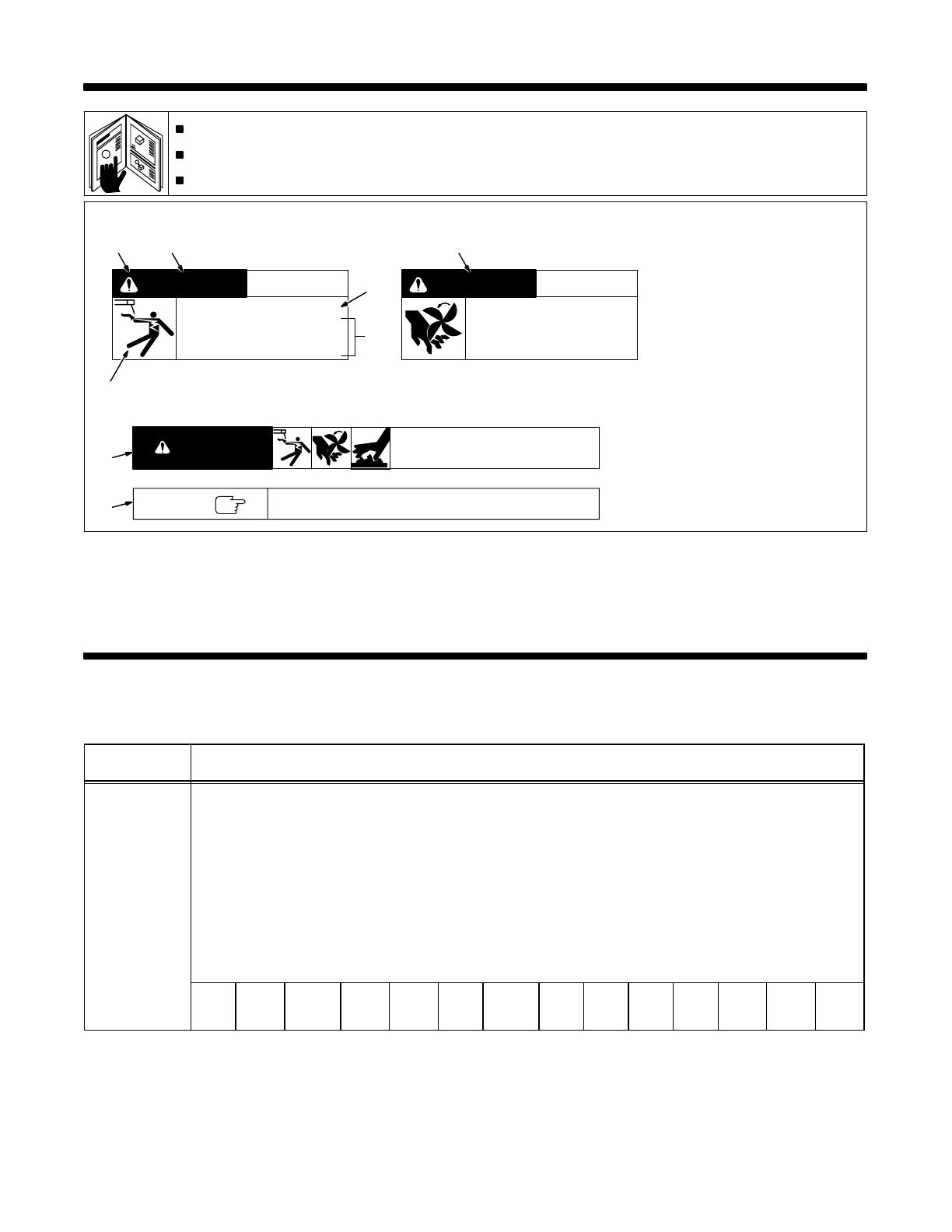
1 Safety Alert Symbol
2 Signal Word
WARNING means possible death
or serious injury can happen.
CAUTION means possible minor
injury or equipment damage can
happen.
3 Statement Of Hazard And Re-
sult
4 Safety Instructions To Avoid
Hazard
5 Hazard Symbol (If Available)
6 Safety Banner
Read safety blocks for each sym-
bol shown.
7 NOTE
Special instructions for best oper-
ation − not related to safety.
2
NOTE
ELECTRIC SHOCK can kill.
• Do not touch live electrical parts.
• Disconnect input power before
installing or servicing.
WARNING
READ SAFETY BLOCKS at start of
Section 3-1 before proceeding.
WARNING
5
4
6
7
1 2
CAUTION
MOVING PARTS can injure.
• Keep away from moving parts.
• Keep all panels and covers closed
when operating.
3
Turn Off switch when using high frequency.
Figure 1-1. Safety Information
SECTION 2 − SPECIFICATIONS
Table 2-1. Transformer
Specification
Description
Type Of Output Three-Phase, 7 kVA, 200/220 Volts AC, 50/60 Hz
Rated Output 7 kVA At 100% Duty Cycle (See Section 2-1)
Type Of Input
Power
Three-Phase; 50/60 Hz; 190, 200, 207.5, 220, 230, 240, 287.5, 380, 400, 415, 440, 460, 480, Or 575 Volts AC
Overall
Dimensions
See Figure 3-3
Weight Net: 220 lb (100 kg)
Input Amperes At
Rated Output
190 V
21 A
200 V
20 A
207.5 V
19 A
220 V
18 A
230 V
18 A
240 V
17 A
287.5 V
14 A
380 V
11 A
400 V
10 A
415 V
10 A
440 V
9 A
460 V
9 A
480 V
8 A
575 V
7 A
OM-162 322 Page 2
2-1. Duty Cycle
CAUTION
EXCEEDING DUTY CYCLE RATINGS will damage unit.
• Do not exceed indicated duty cycles.
warn7.1 2/92
Duty cycle is how long the unit can operate within a ten minute period without causing overheating or damage. This unit
is rated at 100% duty cycle allowing continuous operation at rated load.
SECTION 3 − INSTALLATION
3-1. Typical Controller Transformer Connections
ST-800 085
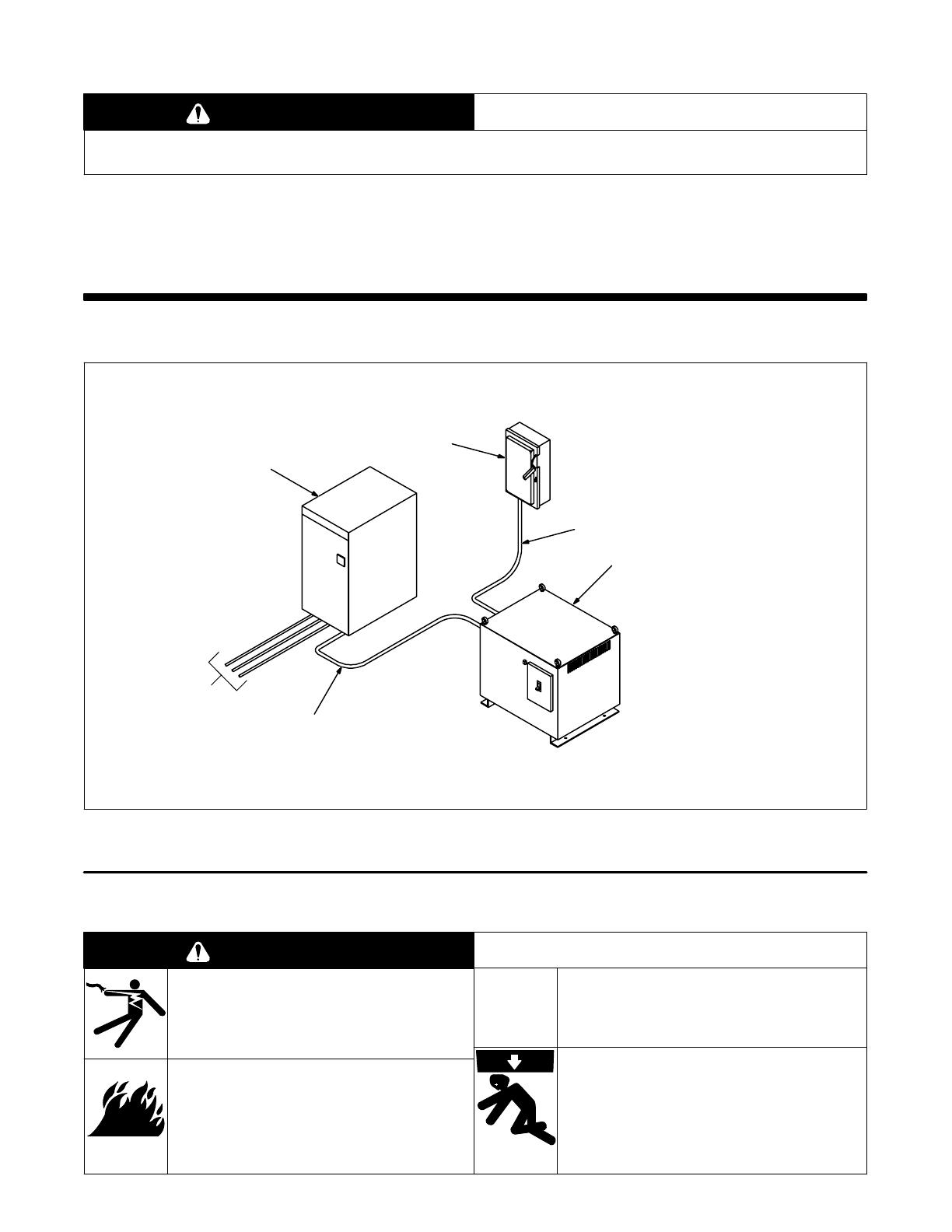
1 Robot Control
2 Line Disconnect Device (Line
Disconnect Switch Shown)
3 Input Power Cable
4 Controller Transformer
5 Output Power Cable
1
Interconnecting
Control Cords
To Robot
5
4
3
2
Figure 3-1. Typical Controller Transformer Connections
3-2. Selecting A Location And Moving Transformer
ELECTRIC SHOCK can kill.
• Do not touch live electrical parts.
• Turn Off transformer, and disconnect input power
conductors from deenergized supply line BEFORE
moving transformer.
FIRE OR EXPLOSION can result from
placing unit on, over, or near com-
bustible surfaces.
• Do not locate unit on, over, or near combustible
surfaces.
• Do not install unit near flammables.
BLOCKED AIRFLOW causes over-
heating and possible damage to unit.
• Do not block or filter airflow.
Warranty is void if any type of filter is used.
FALLING EQUIPMENT can cause
serious personal injury and equipment
damage.
• Use lifting eyes to lift unit only, NOT running gear,
gas cylinders, or any other accessories.
• Use equipment of adequate capacity to lift the unit.
WARNING
swarn11.1* 3/93

OM-162 322 Page 3
Ref. ST-800 073
1 18 in (460 mm) Open Space
On Sides And Bottom For
Good Airflow
2 Lifting Eyes
Use lifting eyes to move unit.
3 Lifting Forks
If using lifting forks, extend forks out
opposite end of unit.
4 Rating Label
Locate unit near correct input pow-
er supply.
Left
Bottom
Right
1
2
Moving With Lifting Eyes Moving With Lifting Forks
OR
3
4
Figure 3-2. Location and Movement Of Transformer
To anchor controller transformer to a foundation or mounting surface, see
Installation section in robot Owner’s Manual.
NOTE
Ref. ST-800 072
B
A
C
Inches Millimeters
A 19 483
B 17-1/2 445
C 21-3/4 552
D 7/8 22
E 19-3/4 502
F 18 457
G 2-7/8 73
H 10 254
J 15-3/4 400
K 11/16 Dia 17 Dia
4 Holes 4 Holes
D
E
F
G
HJ
K
Figure 3-3. Overall Dimensions And Base Mounting Hole Layout
OM-162 322 Page 4
3-3. Output Connections To Robot Control And Controller Transformer
ELECTRIC SHOCK can kill.
• Do not touch live electrical parts.
• Install a fusible line disconnect device in the input
circuit to the transformer.
• Connect output conductors to Robot Control and
controller transformer before connecting to the
three-phase input power.
• Turn Off controller transformer and Robot Control,
and disconnect input power before making any
output connections.
• Have only qualified persons install unit.
• Installation must meet National Electrical Code and
all other codes.
STATIC ELECTRICITY can damage
parts on circuit boards.
• Put on grounded wrist strap BEFORE making
connections inside Robot Control.
WARNING
swarn3.1* 2/93 / fwarn5.1* 9/91
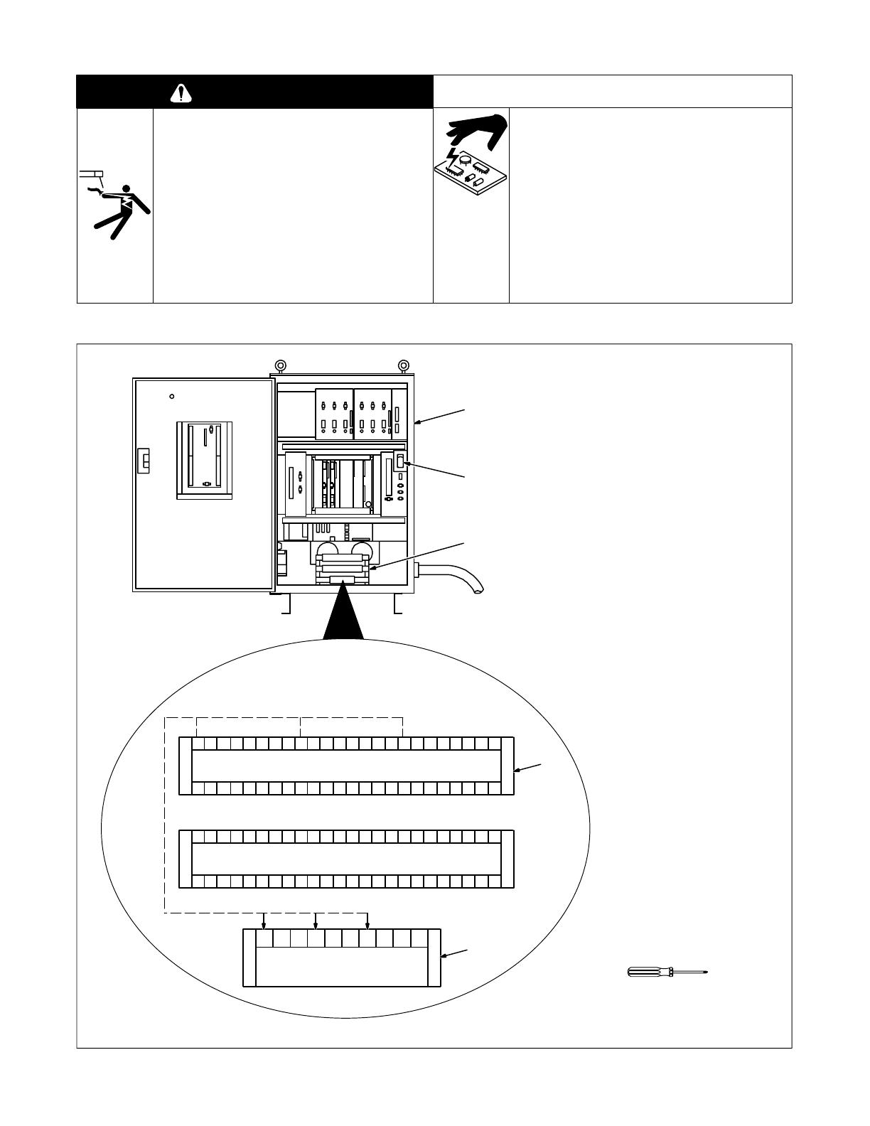
A. Disconnecting Transformer Within Robot Control
ST-156 787-A / Ref. S-0246
Open Robot Control cabinet door,
and turn power switch handle to Re-
set/Open position (see robot Own-
er’s Manual).
1 Robot Control
2 Main Transformer TF10
3 Top U-V-W Terminal Block
4 R-S-T Terminal Block
Disconnect three leads connected
to upper half of terminals U, V, and
W.
Reconnect three leads to upper half
of terminals R, S, and T.
5 Breaker NFB1
Go on to Figure 3-5.
1
Tools Needed:
UUUUUUU UVVV VVVV VWWWWWWWW
123456 7 12 34567 12 34567
UUUUUUU UVVV VVVV VWWWWWWWW
8 9 10 11 13 14 15
R R1 R2 S S1 S2 T T1 T2 Sh
12 8 9 10 11 13 14 1512 8 9 10 11 13 14 1512
4
3
5
2
Figure 3-4. Disconnecting Transformer Within Robot Control
OM-162 322 Page 5
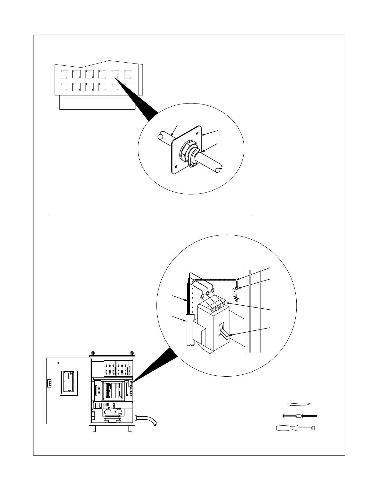
B. Connecting Output Cable To Robot Control
Select conductor size and length
using Table 3-2. Conductor
insulation must comply with
national, state, and local electrical
codes. Use lugs of proper
amperage capacity and correct
hole size.
1 Cover Plate
Use this location for routing output
cord into control.
2 Strain Relief Connector
3 Output Cable
Determine cord insulating jacket
diameter, and cut off
stepped-portion from strain relief
for appropriate size opening to fit
over cord. Insert conductors
through strain relief.
4 Breaker NFB1
5 Line Terminals
6 Ground Terminal
7 Grounding Conductor
8 Output Conductors
Connect output conductors to line
terminals and grounding conductor
to ground terminal.
Close Robot Control cabinet door.
7 mm
Ref. S-0782 / ST-153 666 / ST-156 787-A / S-0819
1
Tools Needed:
2
3
6
5
4
7
3
8
Right Side Of
Robot Control
Figure 3-5. Connecting Output Cable To Robot Control
OM-162 322 Page 6
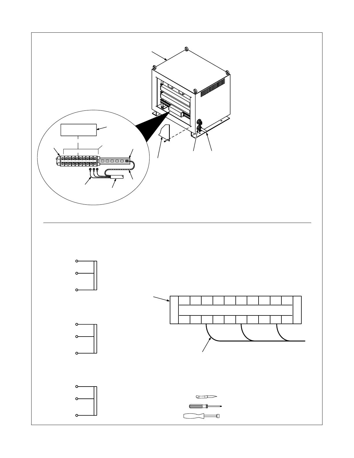
C. Connecting Output Cable To Controller Transformer
1 Controller Transformer
2 Rear Panel
Remove rear panel.
3 Strain Relief Connector
4 Output Cable From Robot
Control
Determine cord insulating jacket
diameter, and cut off
stepped-portion from strain relief
for appropriate size opening to fit
over cord. Insert conductors
through strain relief.
5 Output Terminal Block
6 Clear Cover
Remove cover from terminal block.
7 Line Terminals
8 Ground Terminal
9 Grounding Conductor
10 Output Conductors
Connect output conductors to lower
half of line terminals using diagram
below. Connect grounding
conductor to ground terminal.
Reinstall cover over terminal block.
Reinstall rear cover or go on to
Section 3-4.
Tools Needed:
10 mm
ST-800 077-A / Ref. S-0817
10
R2
R1
R
220V
200V
0V
S2
S1
S
220V
200V
0V
T2
T1
T
220V
200V
0V
R R1 R2 S S1 S2 T T1 T2 Sh
Output Terminal
Connection Diagram
Example Of Output Conductor
Connection For 220 Volts Output
5
1
6
7
8
9
10
5
4
2
34
Figure 3-6. Connecting Output Cable To Controller Transformer
OM-162 322 Page 7
3-4. Input Connections To Controller Transformer
WARNING
ELECTRIC SHOCK can kill.
• Do not touch live electrical parts.
• Turn Off control transformer and Robot Control, and disconnect input power before inspecting or installing.
• Have only qualified persons install unit.
• Installation must meet National Electrical Code and all other codes.
INCORRECT INPUT VOLTAGE JUMPER LEAD PLACEMENT can damage unit.
• Position input voltage jumper leads as shown in Figure 3-7 and Table 3-1.
swarn3.1* 2/93
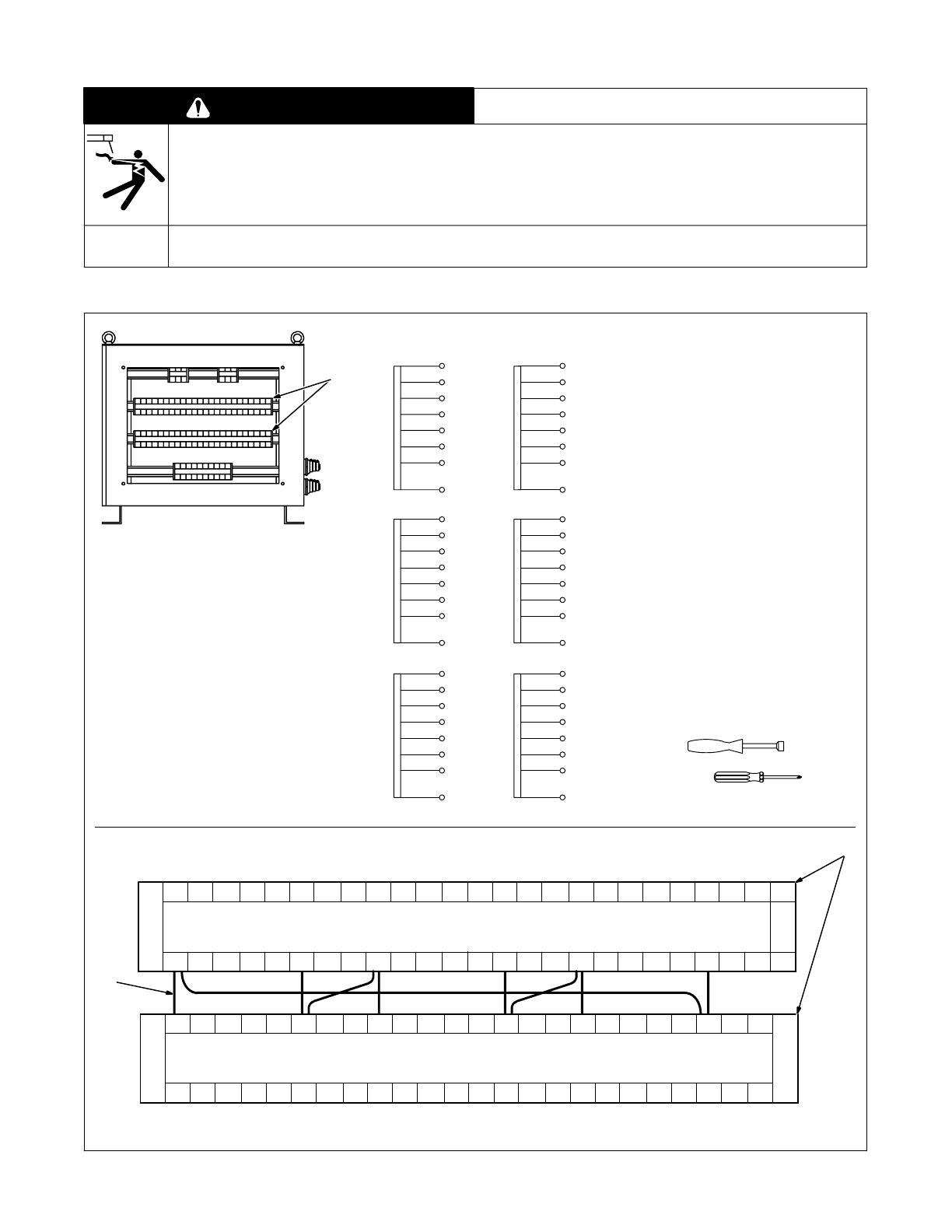
A. Positioning Jumper Leads
ST-800 074 / Ref. S-0817
Nine input voltage jumper leads are
supplied in a bag for installing on the
input voltage terminal blocks.
Jumper leads allow operation on
different input voltages.
Check input voltage available at
site.
Remove rear panel.
1 Input Voltage Terminal Blocks
Remove clear covers from terminal
blocks.
2 Jumper Leads
Install jumper leads to match input
voltage using Table 3-1 and
diagram.
In example, jumper leads are
shown in 230 volt positions listed in
Table 3-1.
Reinstall rear panel or go on to
Figure 3-8.
Tools Needed:
10 mm
1
U7
U6
U5
U4
U3
U2
U1
U
287.5V
240V
230V
220V
207.5V
200V
190V
0V
V7
V6
V5
V4
V3
V2
V1
V
287.5V
240V
230V
220V
200V
190V
0V
W7
W6
W5
W4
W3
W2
W1
W
287.5V
240V
230V
220V
200V
190V
0V
U15
U14
U13
U12
U11
U10
U9
U8
287.5V
240V
230V
220V
200V
190V
0V
V15
V14
V13
V12
V11
V10
V9
V8
287.5V
240V
230V
220V
200V
190V
0V
W15
W14
W13
W12
W11
W10
W9
W8
287.5V
240V
230V
220V
200V
190V
0V
207.5V
207.5V
207.5V
207.5V
207.5V
Input Terminal
Connection Diagram
U1 U2 U3 U4 U5 U6 U7 V V1 V2 V3 V4 V5 V6 V7 W W1 W2 W3 W4 W5 W6 W7
U8 U9 U10 U11 U12 U13 U14 U15 V8 V9 V10 V11 V12 V13 V14 V15 W8 W9 W10 W11 W12 W13 W14 W15
U
Example Of Jumper Lead Connection For 230 Volts Input (See Table 3-1)
2
1
Figure 3-7. Input Voltage Jumper Leads Location

OM-162 322 Page 8
Table 3-1. Input Voltage Tap Connections
Ref. S-163 729
Input Voltage Jumper Lead Positions
190 V
200 V
208 V
220 V
230 V
240 V
380 V
400 V
415 V
440 V
460 V
480 V
575 V
U − U8,
V − V8,
W − W8,
U1 − U9, U9 − V
V1 − V9, V9 − W
W1 − W9, W9 − U
U − U8,
V − V8,
W − W8,
U2 − U10, U10 − V
V2 − V10, V10 − W
W2 − W10, W10 − U
U − U8,
V − V8,
W − W8,
U3 − U11, U11 − V
V3 − V11, V11 − W
W3 − W11, W11 − U
U − U8,
V − V8,
W − W8,
U4 − U12, U12 − V
V4 − V12, V12 − W
W4 − W12, W12 − U
U − U8,
V − V8,
W − W8,
U5 − U13, U13 − V
V5 − V13, V13 − W
W5 − W13, W13 − U
U − U8,
V − V8,
W − W8,
U6 − U14, U14 − V
V6 − V14, V14 − W
W6 − W14, W14 − U
U1 − U8,
V1 − V8,
W1 − W8,
U9 − V
V9 − W
W9 − U
U2 − U8,
V2 − V8,
W2 − W8,
U10 − V
V10 − W
W10 − U
U3 − U8,
V3 − V8,
W3 − W8,
U11 − V
V11 − W
W11 − U
U4 − U8,
V4 − V8,
W4 − W8,
U12 − V
V12 − W
W12 − U
U5 − U8,
V5 − V8,
W5 − W8,
U13 − V
V13 − W
W13 − U
U6 − U8,
V6 − V8,
W6 − W8,
U14 − V
V14 − W
W14 − U
U7 − U8,
V7 − V8,
W7 − W8,
U15 − V
V15 − W
W15 − U

S-0092-F
OM-162 322 Page 9
B. Connecting Input Power
Have only qualified persons make
this installation.
Remove rear panel.
1 Line Disconnect Device Of
Proper Rating
2 Input Conductors
3 Grounding Conductor
Select size and length using
Table 3-2. Conductor rating must
comply with national, state, and
local electrical codes. Use lugs of
proper amperage capacity and
correct hole size.
4 Strain Relief Connector
Determine cord insulating jacket
diameter, and cut off
stepped-portion from strain relief
for appropriate size opening to fit
over cord. Insert conductors
through upper strain relief.
5 Input Terminal Board
6 Line Terminals
7 Ground Terminal
Connect grounding conductor and
input conductors to line terminals
and to ground terminal.
Install and connect grounding
conductor and input conductors in
conduit or equivalent to
deenergized line disconnect
device.
Be sure grounding conductor goes
to an earth ground.
Reinstall rear panel.
8 Overcurrent Protection
Select type and size using
Table 3-2. Install into deenergized
line disconnect device (fused
disconnect switch shown).
ssb2.4* 3/93 − ST-800 076
1
Tools Needed:
10 mm
8
3
4
7
3
2
6
5
Figure 3-8. Input Power Connections
Table 3-2. Electrical Service Requirements*
Input Voltage
190 200 208 220 230 240 288 380 400 415 440 460 480 575
Input Amperes At Rated
Output
21 20 19 18 18 17 14 11 10 10 9 9 8 7
Recommended Standard
Fuse Or Circuit Breaker
Rating In Amperes
1
30 30 30 30 25 25 20 15 15 15 15 15 15 10
Input Conductor Size In
AWG/Kcmil
2
10 10 12 12 12 12 14 14 14 14 14 14 14 14
Max Input Conductor
Length In Feet (Meters)
3
112
(34)
124
(38
80
(24)
90
(27)
98
(30)
107
(33)
99
(30)
173
(53)
192
(58)
206
(63)
232
(71)
253
(77)
276
(84)
396
(121)
Grounding Conductor Size
In AWG/Kcmil
4
10 10 12 12 12 12 14 14 14 14 14 14 14 14
*
These values are calculated from the 1990 edition of the National Electrical Code (NEC).
1 Recommended fuse or circuit breaker size is that closest to 150% of rated input amperage of the welding power source. Article 630-12(a) of NEC
allows fuse or circuit breaker sizing up to 200% of rated input amperage.
2 Input conductor size is for insulated copper wire with 75°C rating with not more than three single current-carrying conductors in a cable or raceway
(Table 310-16 of NEC).
3 Maximum length is to prevent more than a 3% voltage drop between service entrance and input terminals of the welding power source (Articles
210-19(a) and 215-2(b) of NEC).
4 The grounding conductor shall be colored or identified as specified in the NEC. Grounding conductor size for copper wire is not required to be larger
than input conductor (Article 250-95 of NEC).
OM-162 322 Page 10
SECTION 4 − OPERATING, MAINTAINING &
TROUBLESHOOTING
WARNING
ELECTRIC SHOCK can kill.
• Do not touch live electrical parts.
• Turn Off controller transformer and Robot Control,
and disconnect input power before inspecting,
maintaining, or servicing.
HOT PARTS can cause severe burns.
• Allow cooling period before maintaining or servicing.
Maintenance and troubleshooting to be performed only
by qualified persons.
swarn8.1* 2/93
4-1. Operating Controller Transformer
1 Pilot Light
2 Power Switch
Use switch to turn unit and pilot light
On and Off.
The Power switch is also a circuit
breaker protecting the unit from
damage due to current flow
exceeding 50 A. If an overload
occurs and the breaker opens,
output stops. If breaker opens,
reduce load, and place switch in On
position.
Ref. ST-800 072
1
2
Figure 4-1. Power Switch And Pilot Light
Install & Connect
Robot Control
Turn On Line
Disconnect
Device
Turn On
Transformer
Turn On Robot
Control
Install &
Connect
Transformer
Figure 4-2. Sequence Of Operating Transformer
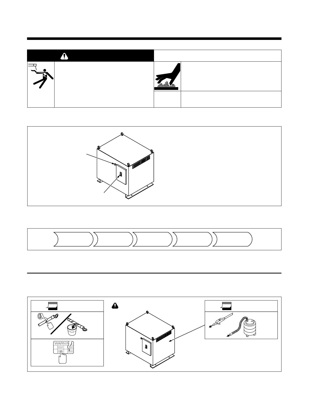
4-2. Routine Maintenance
Turn Off all power before maintaining.
Ref. ST-800 072
3 Months
OR
Blow Out
Or
Vacuum
Inside
Replace
Unreadable
Labels
6 Months
Tape Or
Replace
Cracked
Cable
Figure 4-3. Maintenance Schedule

OM-162 322 Page 11
4-3. Troubleshooting
READ SAFETY BLOCKS at start of
Section 4 before proceeding.
WARNING
Table 4-1. Troubleshooting
Trouble Remedy Section
Transformer completely inoperative;
pilot light not on.
Be sure line disconnect device is On. 3-4C
Check Power switch, and place in On position if necessary. 4-1
Check and replace line fuse(s) if necessary. Reset circuit breaker. 3-4C
Check for proper input connections. 3-4
Low or high output power; pilot light is on. Check for proper input connections. 3-4
SECTION 5 − PARTS LIST
Description
Part
No.
Dia.
Mkgs. Quantity
(OPT)TF10 +155 369 UNIT TRANSFORMER, 7kVA 1. . . . . . . . . . . . . . . . . . . . . . . . . . . . . . . . . . . . . . . . . . . . . .
134 327 LABEL, warning general precautionary 1. . . . . . . . . . . . . . . . . . . . . . . . . . . . . . . . . . . . . . . . . . . . . . . . . . .
+When ordering a component originally displaying a precautionary label, the label should also be ordered.
BE SURE TO PROVIDE MODEL AND SERIAL NUMBER WHEN ORDERING REPLACEMENT PARTS.

/