Longshine LCS-C844MC User manual
- Category
- Network media converters
- Type
- User manual
This manual is also suitable for
Longshine LCS-C844MC is a high-performance and versatile device that offers a wide range of capabilities for various applications. This device is equipped with advanced hardware and software features that enable it to excel in demanding environments and provide reliable connectivity and functionality. Here's a brief overview of the key features and potential use cases of Longshine LCS-C844MC:
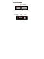
- Industrial-grade design: The LCS-C844MC is designed to withstand harsh industrial environments, making it suitable for use in factories, warehouses, and other challenging conditions. It features a rugged metal enclosure, extended operating temperature range, and high immunity to electromagnetic interference, ensuring reliable operation even in demanding settings.
Longshine LCS-C844MC is a high-performance and versatile device that offers a wide range of capabilities for various applications. This device is equipped with advanced hardware and software features that enable it to excel in demanding environments and provide reliable connectivity and functionality. Here's a brief overview of the key features and potential use cases of Longshine LCS-C844MC:
- Industrial-grade design: The LCS-C844MC is designed to withstand harsh industrial environments, making it suitable for use in factories, warehouses, and other challenging conditions. It features a rugged metal enclosure, extended operating temperature range, and high immunity to electromagnetic interference, ensuring reliable operation even in demanding settings.


-
 1
1
-
 2
2
-
 3
3
-
 4
4
-
 5
5
-
 6
6
-
 7
7
-
 8
8
-
 9
9
-
 10
10
-
 11
11
-
 12
12
-
 13
13
-
 14
14
-
 15
15
-
 16
16
-
 17
17
-
 18
18
-
 19
19
-
 20
20
-
 21
21
-
 22
22
-
 23
23
-
 24
24
-
 25
25
-
 26
26
-
 27
27
-
 28
28
-
 29
29
-
 30
30
-
 31
31
-
 32
32
-
 33
33
-
 34
34
-
 35
35
-
 36
36
-
 37
37
-
 38
38
-
 39
39
-
 40
40
-
 41
41
-
 42
42
-
 43
43
-
 44
44
-
 45
45
-
 46
46
-
 47
47
-
 48
48
-
 49
49
-
 50
50
-
 51
51
-
 52
52
-
 53
53
-
 54
54
-
 55
55
-
 56
56


Longshine LCS-C844MC User manual
- Category
- Network media converters
- Type
- User manual
- This manual is also suitable for
Longshine LCS-C844MC is a high-performance and versatile device that offers a wide range of capabilities for various applications. This device is equipped with advanced hardware and software features that enable it to excel in demanding environments and provide reliable connectivity and functionality. Here's a brief overview of the key features and potential use cases of Longshine LCS-C844MC:
- Industrial-grade design: The LCS-C844MC is designed to withstand harsh industrial environments, making it suitable for use in factories, warehouses, and other challenging conditions. It features a rugged metal enclosure, extended operating temperature range, and high immunity to electromagnetic interference, ensuring reliable operation even in demanding settings.
Ask a question and I''ll find the answer in the document
Finding information in a document is now easier with AI
Related papers
Other documents
-
Lantronix XPress-DR-IAP User guide
-
Moxa MGate MB3170/MB3270 Series User manual
-
-
-
CTC Union FRM220-NMC User manual
-
Korenix JetPort 5601 User manual
-
Moxa NPort 6400/6600 Series User manual
-
-
-
Moxa NPort 5000AI-M12 Series User manual