Page is loading ...

KYROS
INSTRUCTION MANUAL
DIGITAL ELECTRONIC WATER HEATER
Information, operation & installation

2
Contents:
1. Introduction.............................................................................................................................................. 3
2. Component checklist .......................................................................................................................... 4
3. General requirements ................................................................................................................................4
4. Plumbing Installation .................................................................................................................................6
5. Electrical installation ................................................................................................................................11
6. Filling and commissioning .......................................................................................................................12
7. Product information and operation .........................................................................................................13
7.1. Control panel .... ..............................................................................................................................13
7.2. Switching on and off (stand-by) ................... ..............................................................................14
7.3. Adjust the day and time ..................................................................................................................15
7.4. Adjust the temperature ...................................................................................................................15
7.5. Lock the control panel ....................................................................................................................16
7.6. Main Menu ....... ...............................................................................................................................16
7.6.1. Settings sub-menu ..............................................................................................................17
7.6.2. Energy sub-menu ...................................................................................................................18
7.6.3. Equilibrium / Balance sub-menu ........................................................................................20
7.6.4. Program sub-menu ......................................................................................................... 20
8. Fuzzy Logic Energy Control technology .......................................................................................... 28
9. Guidance ..................................................................................................................................................28
10. Servicing and maintenance ..................................................................................................................28
11. Troubleshooting .....................................................................................................................................29
12. Safety precautions .................................................................................................................................30
13. Rointe Product Guarantee ..................................................................................................................31
14. European Directive..................................................................................................................................33
15. Dimensions & Technical Characteristics ............ ................................................................................34
16. Commissioning and service history records .......................................................................................36
17. Certificate of Guarantee ........................................................................................................................39

3
1. Introduction
Designed with the user in mind, this product is a high quality, unvented domestic hot water cylinder
with an enamelled steel tank. The product is suitable for domestic hot water systems where the cold
mains water supply has a maximum supply pressure of 0.9 MPa. Reduced performance is available
at lower pressures, but the product is not suitable for pressures lower than 0.15 MPa and a flow rate
of 20 litres per minute.
The necessary safety equipment to comply with all national legislation is available for purchase
from Rointe.
The main features of this product are:
• A backlit display
• Enamelled steel tank
• Low consumption due to patented Fuzzy Logic Energy Control technology
• 4 pre-installed programmes
• Anti-legionella function
• Water Heating Progress function
IMPORTANT - Please read this Instruction Manual carefully to ensure correct operation. It is impor-
tant that this manual is left with the product after installation.

4
2. Component check list
The product comes with the following components. Please check through the components supplied
and ensure that all parts are present:
• Product with sheathed heating elements, digital thermostat, TFT screen and manual reset ther-
mal cut-out.
• T/P valve 0.7 MPa 90ºC and electrolytic fittings.
• Installation and user manual.
Please contact our Technical Service department on 0203 321 5929 to find out how to acquire
the safety fittings.
3. General requirements
3.1. Building regulations
The domestic hot water cylinder MUST be installed by a competent person in accordance with
section G3 of the current Building Regulations.
3.2. Important
It is important that the installer reads and understands these instructions and unpacks and
familiarises themselves with the equipment before commencing the installation. Failure to observe
these installation instructions could invalidate the guarantee.
3.3. Water supply
The water supply to the cylinder should be potable water direct from a public mains water supply with
any water treatment equipment functioning correctly.
For optimum performance the unit should be fed via a 15 mm or 22 mm diameter supply pipe direct
from the mains water entry point to the property and supplies a maximum pressure of 0.9 MPa. The
unit can operate with a minimum supply pressure of 0.15 MPa and a flow rate of at least 20 litres per
minute, but flow from the outlets will be low if several outlets are used simultaneously. The cylinder
control equipment is factory set to limit the system operating pressure to 0.3 MPa. The maximum
supply pressure into the pressure-reducing valve is 0.9 MPa.
3.4. Taps and fittings
All taps and fittings incorporated in the unvented system should have a rated operating pressure of
0.7 MPa or above.

5
3.5. Location
The unit is designed to be vertically wall mounted, indoors, in a frost-free environment. When choosing
a suitable location for the cylinder, consideration should be given to the routing of the discharge
pipe to a convenient point and also the availability of an adequate power supply for connecting the
sheathed heating elements.
The wall onto which the cylinder is mounted should be of good sound masonry construction capable
of holding the weight of the cylinder when full of water (see Technical Specifications on page 36 for
weights).
The position of the cylinder should provide easy access for servicing the controls and replacing the
sheathed heating element should the need arise.
Pipe runs should be made as short as possible and lagged to prevent heat loss.
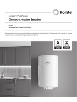
To allow for servicing and repairs, the product must be mounted at least 540 mm above any surface
or object, so that access can be gained to electric connectors and the heating elements may be
removed (see Figure 1).
Figure 1 - Mounting
The unit should be mounted close to an external wall so that the discharge pipe D2 (see Figure 2,
page 7) can be routed to a safe visible place.
The tundish should be mounted in a visible location so that it may easily be inspected.

6
The distance between holes for the wall mounting depends on the model, see the following table for
reference:
MODEL
Horizontal width between holes
(mm)
Height between upper and
lower holes (mm)
KWI050DHW2 350 340
KWI075DHW2 350 573
KWI100DHW2 350 768
KWI150DHW2 350 595
KWI200DHW2 350 685
3.6. Storage and handling
If the cylinder is not being installed immediately, it should remain in its original box with all pipe end
protective caps in situ to prevent damage. We recommend that the cylinder be transported to its
installation position with the outer box in place.
4. Plumbing installation
4.1. Connections
All pipework connections to the cylinder MUST be made in accordance with Figure 1 (page 5) and
Figure 2 (page 7). A drain cock (not supplied) should be fitted in the position shown in Figure 2 (page 7)
to facilitate draining of the cylinder.
4.2. Electrical fittings
The electrical fittings (Figure 2, page 7) must be fitted to the product. If not, the guarantee will be null
and void. Check the T/P Relief Valve (Figure 2, page 7) to ensure it is connected with the electrical
fittings. If not, please contact us by telephoning 0203 321 5929.
4.3. Cold water supply
For best results, the cylinder should be fed by an uninterrupted supply pipe into the pressure reducing
valve (PRV) (Figure 2, page 7) with a maximum supply pressure of 0.9 MPa. The cylinder should not
be used on any system with a supply pressure below 0.15 MPa and a flow rate of less than 20 litres
per minute.

7
4.4. Temperature and pressure relief valve
The temperature and pressure relief valve (T/P Valve) is supplied (Figure 2, page 7). Once the T/P
valve is fitted it should not be removed from the cylinder or tampered with in any way. The valve is pre
calibrated to lift at 0.7 MPa or 90
o
C and any attempt to adjust it will render the guarantee null and void
and could affect the safety performance of the unit.
The outlet of the T/P valve should be routed in 15 mm copper piping in a downward direction alongside
the product to the tundish in a frost-free environment. The outlet of the expansion relief valve must be
T’d into this pipe before the tundish so that any water exiting either valve can be seen draining through
the tundish – see Figure 2 (page 7) and Figure 3 (page 9).
Figure 2 - KYROS cylinder connection arrangement
NO. DESCRIPTION
1
Mains cold water supply
2
Stop Cock (not included)
3
Pressure reducing valve*
4
Check valve*
5
Expansion relief valve*
6
Discharge pipe (22 mm)
7
Drain Cock (not included)
8
Tundish*
9
Expansion vessel*
10
T/P relief valve (included)
11
Electrical fittings (included)
* Available in optional installation kit

8
4.5. Pressure reducing valve
The pressure reducing valve (Figure 2, page 7) should be installed in the cold water supply to the
water heating unit with the arrow pointing in the direction of water flow as shown in Figure 2 (page 7).
This can be connected to a maximum supply pressure of 0.9 MPa.
4.6. Expansion relief valve
This must be installed between the pressure reducing valve and the water heating unit in accordance
with Figure 2 (page 7). No other valve should be fitted between this valve and the cylinder. The
expansion relief valve contains a non return valve.
4.7. Expansion vessel
A suitable expansion vessel (Figure 2, page 7) with a pre-charge pressure of 0.15 or 0.3 MPa is
available in an optional kit for fitting to all water heating units in the range. The expansion vessel
MUST be fitted to the safety group. The expansion vessel MUST be positioned with the entry point at
the bottom – see Figure 2 above.
IMPORTANT: Regular checks must be carried out to ensure that the expansion vessel is correctly
pressurised to 0.15 or 0.3 MPa at all times. – see Figure 2 (page 7).
4.8. Tundish
The tundish (Figure 2, page 7) must not be positioned above or in close proximity to any electrical
current carrying devices or wiring. The installation should conform with the requirements of section
4.9 below.
4.9. Discharge arrangement
The tundish (Figure 2, page 7) must be installed in a position so that it is clearly visible by the user. In
addition, the discharge pipe (Figure 2, page 7) from the tundish should terminate in a safe place where
there is no risk to persons in the vicinity of the discharge, be of metal and:
A) Be at least one pipe size larger than the normal outlet size of the safety device unless its total
equipment hydraulic resistance exceeds that of a straight pipe 9m long, i.e. discharge pipes between
9m and 18m equivalent resistance length should be at least two sizes larger then the normal outlet
size of the safety device, between 18m and 27m at least three sizes larger and so on. Bends must be
taken into account in calculating the flow resistance. Refer to Figure 3 (page 9), Table 1 (page 10) and
Calculated Example 1 (page 10).
B) Have a vertical section of pipe at least 300 mm long below the tundish before any elbows or bends
in the pipework.

9
C) Be installed with a continuous fall.
D) Have discharges visible at both tundish and the final point of discharge, but where this is not
possible or practically difficult, examples of acceptable discharge arrangements are:
• Ideally below a fixed grating and above the water seal in a trapped gully.
• External surfaces such as car parks, hard standings, grassed areas, etc.) are acceptable
providing that where children play or otherwise come into contact with discharges, a wire cage
or similar guard is positioned to prevent contact whilst maintaining visibility.
• Discharge at high level, e.g. into a metal hopper and metal down pipe with the end of the
discharge pipe clearly visible (tundish visible or not) or onto a roof capable of withstanding high
temperature discharges of water and 3 m from any plastic guttering system that would collect
such discharges (tundish visible).
• Where a single pipe serves a number of discharges such as in blocks of flats, the number served
should be limited to not more than six systems so that any installation discharging can be traced
reasonably easily. The single common discharge pipe should be at least one pipe size larger than
the largest individual discharge pipe to be connected. If unvented hot water storage systems are
installed where discharges from safety devices may not be apparent (i.e. in dwellings occupied
by blind, or disabled people), consideration should be given to the installation of an electrically
operated device to warn when discharge takes place.
WARNING - The discharge will consist of scalding water and steam. Asphalt, roofing felt and non-
metallic rainwater goods may be damaged by such discharges.
Figure 3 - Typical discharge pipe arrangement

10
Table 1 - Sizing of copper discharge pipe “D2” for common temperature relief valve outlet sizes
Valve
outlet size
(diameter,
inches)
Minimum size of
discharge pipe D1
(mm)
Min. size of
discharge pipe D2
(mm)
Max. resistance
allowed, expressed
as length of
straight pipe - no
elbows / bends (m)
Resistance created
by each elbow or
bend (m)
G 1/2 15
22
28
35
up to 9
up to 18
up to 27
0.8
1.0
1.4
G 3/4 22
28
35
42
up to 9
up to 18
up to 27
1.0
1.4
1.7
G1 28
35
42
54
up to 9
up to 18
up to 27
1.4
1.7
2.3
Calculated Example 1
The example below is for a 1/2” diameter temperature relief valve with a discharge pipe (D2) having 4
22mm elbows and a length of 7m from the tundish to the point of discharge.
The maximum resistance allowed for a straight length of 22mm copper discharge pipe (D2) from a
1/2” diameter temperature relief valve is 9.0m.
Subtract the resistance for 4 x no 22mm elbows at 0.8m each = 3.2m.
Therefore, the maximum permitted length equates to: 5.8m.
5.8m is less than the actual length of 7m, therefore, calculate the next largest size.
Maximum resistance allowed for a straight length of 28mm pipe (D2) from a 1/2” diameter temperature
relief valve equates to: 18m.
Subtract the resistance for 4 No 28mm elbows at 1.0 each = 4m.
Therefore the maximum permitted length equates to: 14m.
As the actual length is 7m, a 28mm diameter copper pipe will be satisfactory.

11
5. Electrical installation
WARNING - This equipment and pipework must be earthed. All electrical wiring must be carried out
by a competent person and in accordance with the current I.E.E. Wiring Regulations.
5.1. The sheathed heating elements
Two parallel 1.2kW 230v 50Hz sheathed heating elements are pre fitted to the cylinder at the factory.
They are wired in accordance with the instructions given in Figure 4.
5.2. Wiring diagram
The power supply to the product must be via a double pole isolator switch or controller, having
contact separation of at least 3 mm, to comply with BS 6141 and must be fully earthed. In case of an
electric problem, check that the wiring follows Figure 4:
A) The earth wire is connected to the terminal on the cylinder marked with the earth symbol.
B) The live wire is connected to the high temperature cut-out terminal.
C) The neutral wire is connected to the high temperature cut-out terminal.
Figure 4 - Wiring diagram
WARNING - Do not switch on the electricity supply until instructed to do so in the commissioning
procedure and once the product is full of water.

12
6. Filling and commissioning
• Check that the expansion vessel charge pressure is 0.15 or 0.3 MPa.
• Check that all water and electric connections are correctly configured.
• Open the main stopcock and fill the unit. Open successive hot taps starting with the tap furthest
from the product. Leave each tap open for a few moments to allow all air and debris from the
system to exit. Close all of the taps.
• Turn off the mains water supply to the cylinder and drain the system through the drain cock.
• Refill the cylinder with hot taps open and close when water flows freely.
• Manually lift (by rotating the knob) both the expansion relief and the temperature and pressure
relief valves for a short period to remove trapped air from behind the valve seating and to check
the correct function of the discharge arrangement.
• Check all joints for leaks and rectify as necessary.
• With the product full of water, switch on the electricity supply. Check that the cylinder heats the
water and the thermostat operates. Turn on the hot taps to check that warm water is delivered.
• Check that while the unit is heating up, no water exits from either the expansion relief valve or the
temperature and pressure relief valve. If water does exit through the valves check the expansion
vessel pressure and installation.
• Increase the temperature to maximum and allow the unit to heat and the temperature to stabilise.
Check that no water discharges from the valves. Turn on the hot taps to drain the product of hot
water. Set the thermostat to the required temperature and allow the product to reheat ready for use.

13
7. Product information and operation
7.1. Control panel
7.1.1. Keypad
ICON DESCRIPTION
On / Off button
Accept / Confirm button
Decrease temperature
button
Move left button
Increase temperature button
Move right button
Menu button
Move upwards button
MANUAL / AUTOMATIC
button
Move downwards button
7.1.2. Display panel
NO. DESCRIPTION
1
Programming
2
Days of the week
3
Time of day
4
Temperature selected
5
Control panel locked / unlocked
6
MANUAL / AUTOMATIC / PILOT WIRE function indicator
7
COMFORT / ECO / ANTI-FROST mode indicator
8
Fuzzy Logic Energy Control technology indicator /
heating element active indicator
9
Energy consumption indicator
* PILOT WIRE function not available in UK. Only on demand*

14
7.1.3. Symbol information
SYMBOL DESCRIPTION SYMBOL DESCRIPTION
Energy consumption status - green /
amber / red
MANUAL function active
Heating element active
PILOT WIRE function active
* Not available in UK. Only on demand*
Fuzzy Logic Control technology active
AUTOMATIC function active when USER
mode active
COMFORT mode active
MANUAL function active when USER
mode active
ECO mode active
PILOT WIRE function active when USER
mode active
* Not available in UK. Only on demand*
ANTI-FROST mode active Control panel locked through keypad
AUTOMATIC function active Control panel locked through remote
7.2. Switching on and off (stand-by)
To switch the product on, please press the button on the keypad once.
The image to the right will appear on the display panel when the product is
switched on.
After 5 seconds the temperature, time and days of the week will show on the
display panel.
To switch the product off, please press the button again once.
The product will go into stand-by mode with the word ‘STAND-BY’ displayed
on the display panel. After 5 seconds the Rointe logo will appear.

15
7.3. Adjust the day and time
To set the day and time, please press the button on the keypad to access
the Main Menu. Select the `Settings´ menu using the or buttons
on the keypad.
To move left press the button and to move right press the button.
Once the icon is highlighted on the display panel, press the button
to access.
Now use the and buttons again to select the clock option and
press to access.
Use the and buttons to set the hour and then press to confirm.
Then use the and buttons to set the minutes and press to
confirm. Finally, use the and buttons to set the day (1 = Monday, 2
= Tuesday etc.) and confirm by pressing the button.
7.4. Adjust the temperature
To change the temperature, please press the or the button. To
decrease the temperature press the button and to increase the temperature
press the button.
When the water temperature is lower than the set temperature on the display
panel, the product will come on with the symbol appearing in the top
right of the display panel.
When the Fuzzy Logic Energy Control technology is activated the symbol
will replace the symbol in the top right of the display panel.
To learn more about Fuzzy Logic Energy Control technology please see section
8.

16
7.5. Lock the control panel
You can lock the keypad from the product or from a remote control* (optional).
To lock the keypad manually, please hold and press the button AND the
button TOGETHER for 3 seconds. The symbol will appear on the display
panel and the keys will not respond.
To unlock the keypad manually, please hold and press the button AND the
button TOGETHER for 3 seconds.
*To lock the keypad using a remote control, please see the corresponding
instruction manual for the remote control separately.
Please note that the product is locked using a remote control then it can only
be unlocked using the remote control. If the product is locked using a remote
control and you press the keypad on the product then the following image will
appear on the display panel.
7.6. Main Menu
The Main Menu is accessed by pressing the menu button.
You can navigate through the different options available on the menu by pressing
the and buttons to move left and right respectively and to scroll through
all 4 options.
The selected sub-menu will be highlighted with a frame, as shown in the image
to the right on the `Settings´ section of the display panel.
The below icons displayed on the screen take you to the following sub-menus:
Settings Energy
Equilibrium
/ Balance
Program

17
7.6.1. Main Menu: Settings sub-menu
The `Settings´ sub-menu configures the technical parameters of your product.
To access, select the
icon displayed in the Main Menu screen and press
to confirm.
Use the and buttons to move across the different options on the
sub-menu to choose your parameter and press to access.
The below icons displayed on the screen take you to the following parameters:
Display
backlight
brightness
Clear Memory Language Time
• Adjust display backlight brightness
This allows you to change the brightness of the display panel in both the
STAND-BY and ON modes separately. To change the brightness of the display
panel ensure the icon is highlighted and press the button to confirm.
Then with the and buttons you can switch between the two modes.
With the and buttons you can increase or decrease the brightness
as you wish. The cursor indicates the intensity of the light. Once you have set
the required brightness press the button to save and exit.
• Clear the memory
This allows you to clear any information saved in your product. To clear the
memory ensure the icon is highlighted in the `Settings´ sub-menu and
press the button to confirm.
The display panel will show when completed and the language will change
to default.

18
• Change the language
To change the language of your product, ensure the icon is highlighted
in the `Settings´ sub-menu and press the button to access.
Use the and buttons to move up or down respectively until your chosen
language is highlighted and confirm by pressing the button.
LANGUAGE
ENGLISH
FRANÇAIS
ESPAÑOL
PORTUGUÊS
• Adjust the day and time
This option sets the hour, minutes and day of the week in your product. Please
refer to section 7.3.
7.6.2. Main Menu: Energy sub-menu
The `Energy´ sub-menu provides access to functions related to energy
management of the product. To access, select the
icon displayed in the
Main Menu screen and press to confirm.
Use the and buttons to move across the different options on the sub-
menu to choose your function and press to confirm.
The below icons displayed on the screen take you to the following functions:
Water Heating
Progress function
Anti-legionella
function
Effective Power
function
Information

19
• Water Heating Progress function
This function allows you to see the progress of the water heating process
towards the user established target temperature.
To see the progress of the water heating, ensure the icon is highlighted in
the `Energy´ sub-menu and press the button to confirm.
The display will then show the % of water contained in the product that is at the
user defined target. If the % is below 100%, the display will show a symbol
to represent the water that is still to be heated.
• Anti-legionella function
Your product incorporates an anti-legionella function where the product
is automatically set to over 60ºC for at least one hour once a week. When
this mode is active, you will see the screen on the right. You can choose a
time period in days for this function to be active. The product has a default
period of 7 days.
To choose a time period ensure the icon is highlighted in the `Energy´
sub-menu and press the button to access. Use the and
buttons to choose your number of days and press to confirm.
ANTILEGIONAIRE’ S
DISEASE FUNCTION
PERIOD (DAYS)
7
• Effective Power function
To check the Effective Power status of your product, ensure the icon is
highlighted in the `Energy´ sub-menu and press the button to access.
The display panel will then show a status according to the current state of
consumption of the product:
• Working Time
• Total Time
After 6 seconds, the display panel will then show:
• Nominal Power (w)
• Effective Power* (w)
*The effective power is the actual value of its nominal power that the product
consumes during periods of operation.

20
• Information
This function will display the software version, the date of this release and the
rated power of the product.
To access this information, ensure the icon is highlighted in the `Energy´
sub-menu and press the button to confirm. The information will then show
in the display panel.
7.6.3. Main Menu: Equilibrium / Balance sub-menu
The `Balance´ sub-menu/function returns the product to a constant temperature
of 55°C. To activate this function ensure the icon is highlighted in the
`Balance´ sub-menu and press the button to confirm.
The product will return to the display panel in MANUAL function, with the
temperature set to 55ºC.
7.6.4. Main Menu: Program sub-menu
This section explains the operational aspects of your product in its various functions and modes.
What are the functions of MANUAL, AUTOMATIC and PILOT WIRE functions?
MANUAL
This function allows you to change the product between the COMFORT, ECO
and ANTI-FROST modes and to change the temperature (see section 7.4.).
AUTOMATIC
This function will activate the programming that has previously been set in the
product.
PILOT WIRE
This function allows the product to be controlled by a central programmer.
* Not available in UK. Only on demand*
What are the COMFORT, ECO and ANTI-FROST modes?
COMFORT
ECO
ANTI-FROST
From 55ºC to 73ºC From 40ºC to 54.5ºC 7ºC
/