Trendnet TE100-H16R User manual

Category
Networking
Type
User manual

This manual is also suitable for

TE100-H16R/H24R
16/24 Ports
Fast Ethernet
Stackable Hubs
User’s Guide
Fast Ethernet Stackable Hubs User’s Guide
ii
16/24 Ports
Fast Ethernet
Stackable Hubs
User’s Guide
Rev. 01 (AUG., 1998)
505-1100-004
Printed In Taiwan
RECYCLABLE
Fast Ethernet Stackable Hubs User’s Guide
iii
FCC Warning
This equipment has been tested and found to comply with the lim-
its for a Class A digital device, pursuant to Part 15 of the FCC
Rules. These limits are designed to provide reasonable protection
against harmful interference when the equipment is operated in a
commercial environment. This equipment generates, uses, and
can radiate radio frequency energy and, if not installed and used
in accordance with this user’s guide, may cause harmful interfer-
ence to radio communications. Operation of this equipment in a
residential area is likely to cause harmful interference in which
case the user will be required to correct the interference at his own
expense.
CE Mark Warning
This is a Class A product. In a domestic environment, this product
may cause radio interference in which case the user may be re-
quired to take adequate measures.
Fast Ethernet Stackable Hubs User’s Guide
iv
TABLE OF CONTENTS
0ABOUT THIS GUIDE ...........................................................1
Conventions .....................................................................................1
Overview of the User’s Guide..........................................................2
1INTRODUCTION ..................................................................3
Product Description ........................................................................3
Product Features .............................................................................4
2UNPACKING AND SETUP.....................................................5
Unpacking .......................................................................................5
Identifying External Components ..................................................6
Front Panel ......................................................................................6
Rear Panel .......................................................................................7
Installing the Hub...........................................................................9
Installation ......................................................................................9
Rack Mounting ..............................................................................10
3UNDERSTANDING INDICATORS ..........................................11
Hub State Indicators ....................................................................12
100BASE-FX Module Indicators .................................................12
Port State Indicators.....................................................................13
Fast Ethernet Stackable Hubs User’s Guide
v
4MAKING CONNECTIONS ...................................................15
Hub Cascading/Building a Stack ...............................................15
Connectivity Rules ........................................................................16
Hub to End-Station Connection ...................................................17
Hub-to-Hub Uplink.......................................................................19
100Base-FX Module Installation .................................................20
5CABLES AND CONNECTORS .............................................23
100BASE-TX Ethernet Cable and Connectors ............................23
Crossover Cables ...........................................................................25
6SPECIFICATIONS..............................................................27
General ..........................................................................................27
Hub-to-Hub Cascading.................................................................28
LED Indicators..............................................................................28
Environmental and Physical........................................................28
Fast Ethernet Stackable Hubs User’s Guide
About This Guide
1
0 ABOUT THIS GUIDE
This guide discusses how to install and use the 16/24 port stack-
able Fast Ethernet Hubs
Conventions
References in this manual to the 16/24 port stackable Fast
Ethernet Hubs are frequently written simply as “hub” or “hubs”
where the text applies to all models. Model names are normally
used only to differentiate between models where necessary.
Unless differentiated by model name, all information applies to all
models.
Fast Ethernet Stackable Hubs User’s Guide
About This Guide
2
Overview of the Users Guide
Chapter 1, Introduction. Provides information on
Fast Ethernet networks, and introduces the features
of the 16/24 port stackable Fast Ethernet Hubs.
Chapter 2, Unpacking and Setup. Helps you get
started in setting up the hub.
Chapter 3,Understanding Indicators. Describes all
LED indicators on the hub’s front panel. Understand-
ing these indicators is essential to effectively using
the hub.
Chapter 4, Making Connections. Provides informa-
tion on connecting to the hub’s twisted-pair, stacking
hubs, and linking with other 100BASE-TX hubs.
Appendix A, Cables and Connectors. Provides specifi-
cations on the cables and connectors used with the
hubs.
Appendix B, Specifications. Lists the hub’s specifica-
tions.
Fast Ethernet Stackable Hubs User’s Guide
Introduction
3
1
1 INTRODUCTION
This chapter introduces the 16/24 port stackable Fast Ethernet
Hubs, as well as giving some background information about the
technology of the hubs use.
Product Description
Ideal for establishing or enlarging a Fast Ethernet LAN work-
group, the Stackable Fast Ethernet Hub provides port density
options from 16 to 190. The hub is IEEE 802.3u compliant and
falls into the Class II Fast Ethernet hub type. The ports on the
hub are standard RJ-45 connectors for use with Category 5 UTP or
STP cabling.
The hubs in the series, available in 16-port and 24-port models,
can be stacked with up to four hubs in a stack. A stack of four 24-
port hubs gives a total of 96 Fast Ethernet ports. A 16/24 port
stackable Fast Ethernet Hubs stack operates as a Class II Fast
Ethernet repeater, allowing it to be linked to another Class II Fast
Ethernet stack in the same collision domain.
Fast Ethernet Stackable Hubs User’s Guide
Introduction
4
Product Features
The list below highlights the features and specifications of hubs in
the series.
Compatible with the 802.3u 100BASE-TX, 100BASE-FX
Fast Ethernet Class II repeater standards for inter-
operability with other Fast Ethernet network devices.
Uses Category 5 UTP or STP cabling.
Up to 100 Meters of cable length between any com-
puter and the hub with a maximum of 205 meters of
cable between any two network nodes.
16 or 24 100Mbps Fast Ethernet ports.
LED indicators for Power, FX Link/Rx, 100M Activity,
100M Collision and 100M Link/Rx.
Scalable stack containing up to 4 units for a total 64
or 96 (depending on model) 100Mbps UTP/STP ports.
Uplink port allows easy linking of two Fast Ethernet
hub stacks to further expand your network.
Standard-size (19”, 1U height), rack mountable
Optional slide-in module: 100BASE-FX (see Chapter
4 : Making Connections).
Automatic voltage selection (100V to 240V, 50~60Hz)
Fast Ethernet Stackable Hubs User’s Guide
Unpacking and Setup
5
2
2 UNPACKING AND
SETUP
This chapter provides information on the unpacking and initial
installation of your hub stack.
Unpacking
Open the shipping cartons of your hub and carefully unpacks the
contents. The carton should contain the following items:
One Fast Ethernet stackable hub
One AC power cord, suitable for your area’s electrical
power connections
One daisy-chain cable
Four rubber feet to be used for shock cushioning
Screws and two mounting brackets
This User’s Guide
Inspect the hub and all accompanying items. If any item is dam-
aged or missing, report the problem immediately to your dealer.
Fast Ethernet Stackable Hubs User’s Guide
Unpacking and Setup
6
Identifying External Components
This section identifies all the major external components of the
hub. Both the front and rear panels are shown, followed by a de-
scription of each panel feature. The indicator panel is described in
detail in the next chapter.
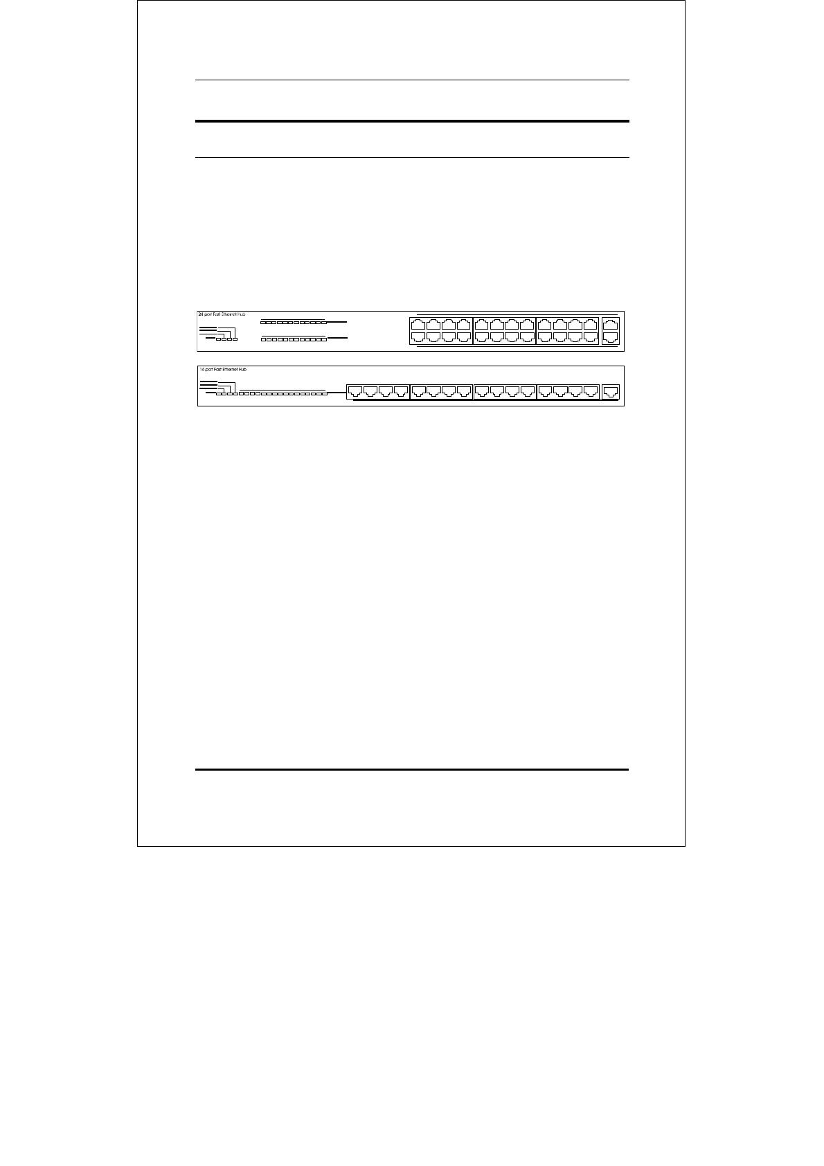
Front Panel
LED Indicator Panel
Refer to the next chapter, Understanding Indicators, for de-
tailed information about each of the hub’s LED indicators.
Twisted-Pair Ports
Use any of these ports to connect stations to the hub. The ports
are MDI-X ports, which means you can use ordinary straight-
through twisted-pair cable to connect the hub to PCs, worksta-
tions, or servers through these ports. If you need to connect to
another device with MDI-X ports such as another hub or an
Ethernet switch, you should use a crossover cable, or connect
using the Uplink port (described below). For more information
about crossover connection, see the Crossover Cables section.
Uplink Ports
The Uplink port is an MDI port, which means you can connect
the hub (or hub stack) to another device with MDI-X ports us-
Fast Ethernet Stackable Hubs User’s Guide
Unpacking and Setup
7
ing an ordinary straight-through cable, making a crossover ca-
ble unnecessary.
In 24-port model, port 12 and the Uplink-1 port, port 24 and
the Uplink-2 is really the same port, except that their pinouts
are different. Do not use both Port 12 and the Uplink-1
port, Port 24 and the Uplink-2 port at the same time.
In 16-port model, port 16 and the Uplink port, is really the
same port, except that their pinouts are different. Do not use
both Port 16 and the Uplink port at the same time.
Rear Panel
Fast Ethernet Stackable Hubs User’s Guide
Unpacking and Setup
8
Module Slots
Used to install module options for 100BASE-FX connection.
Daisy-Chain IN Port
When cascading a set of stackable Fast Ethernet hubs, this port
should be connected to the Daisy-Chain OUT port of the previ-
ous hub in the stack (usually placed immediately above it). A
cascade of four hubs can be created in this way. The first and
last hubs in the stack use only one of the daisy-chain ports,
while the others use both.
Daisy-Chain OUT Port
Works in conjunction with the Daisy-Chain IN Port (see above).
Connect this port to the Daisy-Chain IN Port of the next hub in
the stack (usually placed immediately below it), using the en-
closed daisy-chain cable.
AC Power Connector
For the power cord.
Fast Ethernet Stackable Hubs User’s Guide
Unpacking and Setup
9
Installing the Hub
Installation
The site where you install the hub stack may greatly affect its per-
formance. When installing, consider the following pointers:
Install the hub stack in a fairly cool and dry place.
See Appendix B, Specifications, for the acceptable
temperature and humidity operating ranges.
Install the hub stack in a site free from strong elec-
tromagnetic field generators (such as motors),
vibration, dust, and direct exposure to sunlight.
Leave at least 10cm of space at the front and rear of
the hub for ventilation.
Install the hub on a sturdy, level surface that can
support its weight, or in an EIA standard-size equip-
ment rack. For information on rack installation, see
the next section, Rack Mounting.
When installing the hub stack on a level surface, attach the rubber
feet to the bottom of each device. The rubber feet cushion the hub
and protect the hub case from scratching.
Fast Ethernet Stackable Hubs User’s Guide
Unpacking and Setup
1
0
Rack Mounting
The hub can be mounted in an EIA standard-size, 19-inch rack,
which can be placed in a wiring closet with other equipment. At-
tach the mounting brackets at the hub’s front panel (one on each
side), and secure them with the provided screws.
Then, use screws provided with the equipment rack to mount each
hub in the rack.
Fast Ethernet Stackable Hubs User’s Guide
Understanding Indicators
11
3
3 UNDERSTANDING
INDICATORS
Before connecting network devices to the hub, take a few minutes
to look over this section and familiarize you with the front panel
LED indicators of your stackable Fast Ethernet hub, depicted be-
low.
Fast Ethernet Stackable Hubs User’s Guide
Understanding Indicators
1
2
Hub State Indicators
Power Indicator
This indicator lights green when the hub is receiving power;
otherwise, it is off.
100M Activity
This indicators indicate data packet on the respective 100Mbps
Fast Ethernet segments will blink green.
100M Collision
This indicators indicate data collisions on the respective
100Mbps Fast Ethernet segments of the hub. (If several hubs
are stacked or linked together, all of them should detect and
indicate the same collision, since collisions span the entire net-
work segment.) Whenever a collision is detected, the respective
COL indicator will briefly blink amber.
100BASE-FX Module Indicators
The FX Link/Rx, indicate a good link to a module installed.
Fast Ethernet Stackable Hubs User’s Guide
Understanding Indicators
1
3
Port State Indicators
There have provide state indicators for each of the twisted-pair
ports on the hub. Each port’s LED status indicators report the
port and indicator for link or receive status.
The following describes each indicator and the meaning of each
condition:
100M Link/Rx
This indicator green when the port is connected to a 100Mbps
Fast Ethernet station , If the station to which the hub is con-
nected is powered off, or if there is a problem with the link, the
LED will remain off. And the indicator blinking green when the
data will be received to all other connected ports.
  • Page 1 1
  • Page 2 2
  • Page 3 3
  • Page 4 4
  • Page 5 5
  • Page 6 6
  • Page 7 7
  • Page 8 8
  • Page 9 9
  • Page 10 10
  • Page 11 11
  • Page 12 12
  • Page 13 13
  • Page 14 14
  • Page 15 15
  • Page 16 16
  • Page 17 17
  • Page 18 18
  • Page 19 19
  • Page 20 20
  • Page 21 21
  • Page 22 22
  • Page 23 23
  • Page 24 24
  • Page 25 25
  • Page 26 26
  • Page 27 27
  • Page 28 28
  • Page 29 29
  • Page 30 30
  • Page 31 31
  • Page 32 32
  • Page 33 33
  • Page 34 34

Trendnet TE100-H16R User manual

Category
Networking
Type
User manual
This manual is also suitable for

Ask a question and I''ll find the answer in the document

Finding information in a document is now easier with AI