Extron MTP T 15HD A AAP User manual
- Category
- Wall & ceiling mounts accessories
- Type
- User manual
This manual is also suitable for

1
Product Category
IMPORTANT:
Go to www.extron.com for the
complete user guide
, installation
instructions, and specifications.
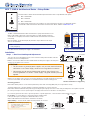
MTP T 15HD A Architectural Series • Setup Guide
The Extron MTP T 15HD A Architectural twisted pair transmitter series accept VGA and audio signals.
z MTP T 15HD A WM
z MTP T 15HD A D
z MTP T 15HD A AAP
This guide provides instructions for an installer to set up and operate these products. For detailed information,
see the MTP T 15HD A Architectural Twisted Pair Transmitters User Guide, available at www.extron.com.
Pre-installation
The MTP T 15HD A WM and D models are installed in a 1-gang electrical wall box. The
MTPT15HD A AAP is attached to a device faceplate or an AAP wall plate. Install the
electrical box or wall plate (see the MTP T 15HD A Architectural Twisted Pair Transmitters
User Guide).
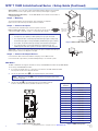
Before installation, run the twisted pair (TP) and audio output cables from the output
device to the transmitter.
NOTE: The cable must be terminated using the same standard (A or B) at both
ends (see figure 1).
Run cables from the 12 VDC power supply to the transmitter.
Installation
Step 1 — Rear Panel Cabling and Adjustments
Turn off or disconnect all equipment power sources. Before mounting the transmitter, make the
following connections and adjustments:
Power — Connect the cables from the included external 12VDC power supply to the rear panel
3.5 mm, 2-pole captive screw connector.
ATTENTION:
• Do not connect any external power supplies until you have read the Attention
notifications in the Power Supply section of the user guide for that device.
• Ne branchez pas de sources d’alimentation externes avant d’avoir lu les
mises en garde dans la section « Power Supply » du guide utilisateur pour cet
appareil.
Wire the 2-pole captive screw connectors as shown in the gures to the right. Plug them into the Power
connectors of the MTPs. The LED indicator on each MTP should be on when receiving power.
Grounding guidelines:
Extron MTP 15HD A products can be adversely affected by electrostatic discharge
(ESD)
if they are not grounded
corr
ectly
.
To prevent malfunctions or product damage, an experienced installer can correctly ground an
Extron MTP 15HD A Architectural series product by grounding the power input port. Insert one end of the grounding wire to the negative
or
ground
pin on the power input connector (see the gure to the right). Tie the other end of
the
wir
e
to an earth
ground.
If you have any questions about how to ground a product in a specic application, contact an Extron
technical
support
specialist.
Pre-Peaking — For long cable runs, set the rear panel pre-peaking switch
to On (see the images to the right). For detailed information, see the
MTPT15HD A Architectural Twisted Pair Transmitters User Guide.
Output Cabling — Connect the TP cable to the rear panel RJ-45 connector.
12345678
Insert Twisted
Pair Wires
Pins:
NOTE: If you are using Enhanced Skew-Free™
A/V cable, use the TIA/EIA T568A standard only.
Pin
1
2
3
4
5
6
7
8
T568A
Wire Color
White-green
Green
White-orange
Blue
White-blue
Orange
White-brown
Brown
T568B
Wire Color
White-orange
Orange
White-green
Blue
White-blue
Green
White-brown
Brown
Figure 1. TP Termination Diagram
AUDIO IN
MTP T 15HD A
COMPUTER IN
Ridges
Smooth
AA
Power Supply
Output Cord
SECTION A–A
Captive Screw
Connector
0.2" (5 mm) MAX
MTP T 15HD A D Power Supply Wiring
50ON
OFF 60
Hz
PRE-
PEAK
ON
OFF
PRE-
PEAK
MTP T 15HD A D MTP T 15HD WM and AAP
Balanced Stereo Input
Tip
Ring
Sleeve (s)
Tip
Ring
LR
Unbalanced Stereo Input
Tip
Sleeve
Tip
Sleeve
LR
ATTENTION:
Potential damage to property.
For unbalanced audio, connect the sleeves
to the center contact ground.
DO NOT connect the sleeves to the
negative (-) contacts.
Ridges
Smooth
AA
Power Supply
Output Cord
SECTION A–A
Captive Screw
Connector
0.2" (5 mm) MAX
MTP T 15HD WM and AAP Power Supply Wiring
Power Supply
Output Cord
SECTION A–A
Ridges
Smooth
AA
Tie
Wrap
Rear
Panel
Ridges
Earth
Ground
3/16"
(5 mm)
MAX
POWER
12V
0.5A MAX

2
MTP T 15HD A Architectural Series • Setup Guide (Continued)
68-2207-50
Rev. D
05 17
PC INPUT
AUDIO
W
all opening
is flush with
edge of bo
x.
Wall Box
Decorator-Style
Faceplate
MTP T 15HD A D
Figure 4. MTP Transmitter Rear Panel
Audio Cabling — For local stereo output, insert stripped audio cable into the rear panel,
direct insertion, 3.5 mm, 5-pole captive screw connector (see the figure on page 1).
EDID Configuration (A D units) — See the EDID Minder section below for information on
configuring the EDID.
Step 2 — Mounting
Secure the transmitter to the electrical box, device faceplate, or wall plate.
figure 2 shows a decorator-style model mounted in a wall box.
Step 3 — Connect the Inputs
Connect the video and audio inputs to the front panel connectors:
High resolution video input — Connect the video input to the 15-pin HD
connector (for RGB, composite, S-video, or component video signals).
NOTES:
• For input only sync signals (no video signals), use sync pins 13 and 14.
• For component video, use the R (R-Y) and R return pins (pins 1 and 6), G (Y)
and G return pins (pins 2 and 7), and B (B-Y) and B return pins (pins 3 and 8).
• For S-video, use the R, R return (C-chroma), G, and G return (Y-luma) pins.
• For composite video, use the G pin and the associated return pin. For
additional genlocked video signals, use the R, B, and associated return pins.
Audio input — Plug a 3.5 mm stereo audio plug into this jack for unbalanced audio input.
Wire the plug as shown in the diagram to the right.
Step 4 — Connect the Output Devices
Connect the TP cable from the transmitter to the input port of an MTP receiver.
Connect the audio output cables (see Audio Cabling above) to a local audio system.
EDID Minder
The MTP T 15HD A D unit supports emulation of factory-installed EDID information through EDID Minder.
To use factory-installed EDID information:
1. If you have not already done so, connect the source device to the MTP 15HD transmitter.
Do not power on the source device at this time.
2. Set the rear panel DIP switch (
1
) to the required frequency (50 or 60 Hz).
NOTE: When the rotary dial (
2
) is set to position 0, the frequency DIP switch
position is ignored.
3. Set the rotary dial (
2
) to the required position (see the table in figure 5).
Positions 1 through F are factory installed. Position 0 is not used.
Figure 5. EDID Settings Table
© 2017 Extron Electronics All rights reserved. www.extron.com
50ON
OFF 60
Hz
PRE-
PEAK
EDID
SELECT
1
2
Rotary Switch
Position
Resolution
0 Not used
1 800x600
2 1024x768 (default)
3 1280x720
4 1280x768
5 1280x800
6 1280x1024
7 1360x768
8 1366x768
9 1400x1050
A 1400x900
B 1600x900
C 1600x1200
D 1680x1050
E 1920x1080
F 1920x1200
Sleeve ( )
Ring (R)
Tip (L)
Figure 2. MTP T 15HD A D Mounting
51
15 11
610
Female
-
 1
1
-
 2
2


Extron MTP T 15HD A AAP User manual
- Category
- Wall & ceiling mounts accessories
- Type
- User manual
- This manual is also suitable for
Ask a question and I''ll find the answer in the document
Finding information in a document is now easier with AI
Related papers
-
Extron MTP T 15HD A D User manual
-
Extron Active Audio AAP User manual
-
-
-
Extron MTP 1500RL 15HD A SEQ User manual
-
-
-
Extron electronics MTP C7 T 15HD R User manual
-
Extron MTP RL 15HD A & MTP RL 15HD A SEQ User manual
-