
Unidrive M200/M201/M300
Step By Step Guide
Guide pas à pas
Schritt-für-Schritt-Anleitung
Guida dettagliata
Guía detallada
Frame sizes 5 to 9
Tailles 5 à 9
Baugrößen 5 bis 9
Taglie da 5 a 9
Tamaños 5 a 9
www.drive-setup.com
EN
Page 2
This guide provides a fast and simple start-up procedure for a basic drive and motor installation.
For help with more advanced installations: Comprehensive user guides, online videos and help tools can be
accessed using the web address or QR code above.
Please read the safety information booklet supplied with the drive before installation or set-up.
For M300, it is essential to read Section 4.2 in the Control Quick Start Guide using the web address or QR
code above prior to using the Safe Torque Off function in safety systems.
FR
Page 12
Ce guide fournit des instructions d’installation et de démarrage simples et rapides d’un variateur.
Pour des informations complémentaires sur des installations moins basiques : des guides de mise en service complets,
des vidéos en ligne et des outils d’aide sont accessibles en utilisant l’adresse Web ou le code QR ci-dessus.
Lire attentivement le livret d’informations relatives à la sécurité fourni avec le variateur avant de procéder à
l’installation ou à la configuration.
Pour l’Unidrive M300, il est essentiel de consulter la section 4.2 du Guide de mise en service rapide -
Contrôle accessible en utilisant l’adresse Web ou le code QR ci-dessus avant d’utiliser la fonction Absence
sûre du couple dans les systèmes de sécurité.
DE
Page 22
Diese Anleitung bietet Informationen für eine schnelle Inbetriebnahme eines einfachen Umrichter-Motor-Systems.
Bei aufwendigeren Systemen: Umfassende Betriebsanleitungen, Online-Videos und Hilfsmittel finden Sie unter unserer
Webadresse oder über den vorstehenden QR-Code.
Bitte lesen Sie die dem Umrichter beiliegende Sicherheitsdokumentation, bevor Sie den Umrichter montieren oder
in Betrieb nehmen.
Beim M300 ist unbedingt der Abschnitt 4.2 in der Steuerungs- Kurzanleitung über die Webadresse bzw. den
vorstehenden QR-Code hinzuzuziehen, um die Safe Torque Off-Funktion in Sicherheitssystemen zu verwenden.
IT
Page 32
Questa guida fornisce una procedura di avviamento semplice e veloce per l'installazione di un azionamento base e del
motore.
Chi avesse bisogno di un supporto per l'installazione di soluzioni più avanzate può consultare le guide complete dell'utente,
i video online e gli strumenti di supporto, cui può accedere utilizzando l'indirizzo Internet o il codice QR qui sopra.
Prima di procedere all'installazione o alla configurazione, leggere l'opuscolo con le informazioni sulla sicurezza
in dotazione all'azionamento.
Per il modello M300, è fondamentale leggere la Sezione 4.2 nella Guida introduttiva al controllo utilizzando
l'indirizzo Internet o il codice QR qui sopra prima di utilizzare la funzione Safe Torque Off in sistemi di sicurezza.
ES
Page 42
Esta guía contiene un procedimiento inicial rápido y sencillo de la instalación básica de accionamiento y motor.
Para obtener ayuda sobre instalaciones más avanzadas: es posible acceder a guías de usuario, herramientas de ayuda
y vídeos online exhaustivos mediante la dirección en Internet o el código QR anterior.
Lea el folleto de información de seguridad suministrado con el accionamiento antes de llevar a cabo la instalación
o la configuración.
Para el accionamiento M300, es imprescindible consultar la sección 4.2 en la Guía de Consulta Rápida sobre
Control mediante la dirección en Internet o el código QR anterior antes de utilizar la función Safe Torque Off en
los sistemas de seguridad.

2 Unidrive M200/M201/M300 Step By Step Guide
Issue Number: 1
English
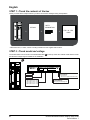
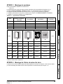
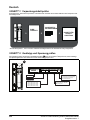
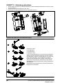
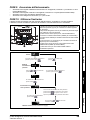
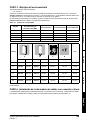
STEP 1: Check the contents of the box
Check you have all the components and your drive has not been damaged during transportation.
* With frame size 7, 8 and 9, surface mounting brackets are also supplied with the drive.
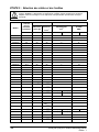
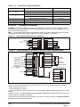
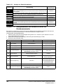
STEP 2: Check model and voltage
The model number can be found on the identification label on the top of the drive. Please check that the model
and the drive voltage range is suitable for the installation.
KIT BOX*
SAFETY
INFORMATION
+
+
+
STEP BY
STEP
GUIDE
1
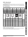
Product line:
Frame size:
Current Rating :
Heavy Duty current rating x10
Drive Format :
A - AC in AC out
E - AC in AC out (without internal choke)
Voltage rating
:
2 - 200 V (200 - 240 ± 10 %)
4 - 400 V (380 - 480 ± 10 %)
5 - 575 V (500 - 575 ± 10 %)
6 - 690 V (500 - 690 ± 10 %)
Derivative
Electrical Specifications
M200 - 05 4 00270 A
1

Unidrive M200/M201/M300 Step By Step Guide 3
Issue Number: 1
English
Français Deutsch Italiano Español
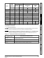
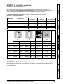
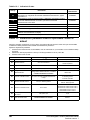
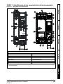
STEP 3: Mount the drive
Ambient temperature operating range:
- 20 °C to 55 °C (- 4 °F to 131 °F).
Output current derating may be required at ambient temperatures >40 °C (104 °F). Refer to the relevant Power
Installation Guide (section 5.1). For UL installations, the maximum ambient temperature permitted is 50 °C (122 °F)
with any specified derating applied.
The drive can be screwed on a wall or Through-panel mounted (Refer to chapter 3 in the Power Installation Guide).
Table 3-1 highlights the clearances.
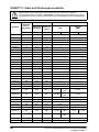
Table 3-1 Recommended spacing
* The Speed Ref Potentiometer adds an additional 11 mm (0.43 in) to the overall depth on a Unidrive M201 only.
STEP 4: Fit cable ground bracket
The cable bracket helps you to organise the cables once they have been connected to the drive.The bracket is
used to clamp the shield of the cables to facilitate EMC compliance (refer to Figure 7-1).
Frame size
Spacing between drive
and enclosure /
EMC filter
Spacing between
drives
Spacing above
drive
Spacing below
drive
5 30 mm (1.18 in) 0 mm (0.00 in) 100 mm (4.0 in) 100 mm (4.0 in)
6 30 mm (1.18 in) 0 mm (0.00 in) 100 mm (4.0 in) 100 mm (4.0 in)
7 45 mm (1.77 in) 30 mm (1.18 in) 60 mm (2.37 in) 100 mm (4.0 in)
8 45 mm (1.77 in) 30 mm (1.18 in) 60 mm (2.37 in) 100 mm (4.0 in)
9 45 mm (1.77 in) 60 mm (2.37 in) 60 mm (2.37 in) 100 mm (4.0 in)
Frame Weight
HW
D
*
Ø
Mounting Overall Mounting Overall Overall Diameter
5
375 mm
(14.76 in)
391 mm
(15.39 in)
106 mm
(4.17 in)
143 mm
(5.63 in)
200 mm
(7.87 in)
6.5 mm (0.26 in)
7.4 kg
(16.3 Ib)
6
378 mm
(14.88 in)
391 mm
(15.39 in)
196 mm
(7.72 in)
210 mm
(8.27 in)
227 mm
(8.94 in)
7.0 mm (0.28 in)
14 kg
(30.9 Ib)
7
538 mm
(21.18 in)
557 mm
(21.93 in)
220 mm
(8.66 in)
270 mm
(10.63 in)
280 mm
(11.02 in)
9.0 mm (0.35 in)
28 kg
(61.70 Ib)
8
784 mm
(30.87 in)
804 mm
(31.65 in)
259 mm
(10.20 in)
310 mm
(12.21 in)
290 mm
(11.42 in)
9.0 mm (0.35 in)
52 kg
(114.6 Ib)
9E
1051 mm
(41.38 in)
1069 mm
(42.09 in)
259 mm
(10.20 in)
310 mm
(12.21 in)
290 mm
(11.42 in)
9.0 mm (0.35 in)
46 kg
(101.4 Ib)
9A
1090 mm
(42.91 in)
1108 mm
(43.62 in)
259 mm
(10.20 in)
310 mm
(12.21 in)
290 mm
(11.42 in)
9.0 mm (0.35 in)
66.5 kg
(146.6 Ib)

4 Unidrive M200/M201/M300 Step By Step Guide
Issue Number: 1
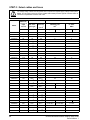
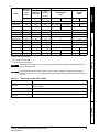
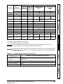
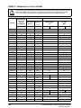
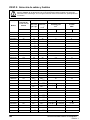
STEP 5: Select cables and fuses
The voltage rating of fuses must be greater than or equal to the highest supply voltage of the system.
Fuses: The AC supply to the drive must be installed with suitable protection against overload. Failure to
observe this requirement will cause risk of fire.
Model
Maximum
continuous
input
current
Fuses Cables
IEC Class
gG or gR
UL
Class CC,
J, or T
*
IEC60364-5-52
mm
2
UL 508C
AWG
A A A Input Output Input Output
05200250 31 40 40 10 8
06200330 48.8 63 60 16 4
06200440 56.6 63 70 25 3
05400270 29 40 35 6 8
05400300 29 40 35 6 8
06400350 36
63
**
40 10 6
06400420 46
63
**
50 16 4
06400470 60
63
**
70 25 3
05500030 4.3 10 10 0.75 16
05500040 5.7 10 10 1 14
05500069 9.3 20 20 1.5 14
06500100 13.2 20 20 2.5 14
06500150 18.7 32 25 4 10
06500190 24.3 40 30 6 10
06500230 29.4 50 35 10 8
06500290 37.1 50 40 10 6
06500350 46.9 63 50 16 6
07200610 67 80 80 35 2
07200750 84 100 100 35 1
07200830 105 125 125 70 1/0
08201160 137
200
** 200***
95 3/0
08201320 166
200
** 225***
2 x 70 2 x 1
09201760 205
250
** 250***
2 x 70 (B1) 2 x 95 (B2) 2 x 2/0
09202190 260
315
** 300***
2 x 95 (B1) 2 x 120 (B2) 2 x 4/0
07400660 74 100 80 35 1
07400770 88 100 100 50 2
07401000 105 125 125 70 1/0
08401340 155
250
** 225***
2 x 50 2 x 1
08401570 177
250
** 225***
2 x 70 2 x 1/0
09402000 232
315
** 300***
2 x 70 (B1) 2 x 95 (B2) 2 x 3/0 2 x 2/0
09402240 267
315
** 350***
2 x 95 (B1) 2 x 120 (B2) 2 x 4/0
07500440 45 50 50 16 4
07500550 62 80 80 25 3
08500630 83
125
** 100***
35 1
WARNING

Unidrive M200/M201/M300 Step By Step Guide 5
Issue Number: 1
English
Français Deutsch Italiano Español
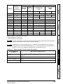
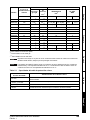
* These fuses are fast acting.
** These fuses are class gR.
*** These fuses are class HSJ.
Table 5-1 Protective ground cable ratings
08500860 104
160
** 150***
50 1
09501040 166
150
** 150***
2 x 70 (B2) 2 x 35 (B2) 2 x 1 2 x 3
09501310 166
200
** 175***
2 x 70 (B2) 2 x 50 (B2) 2 x 1
07600190 20 25 25 10 8
07600240 26 32 30 10 6
07600290 31 40 35 10 6
07600380 39 50 50 16 4
07600440 44 50 50 16 4
07600540 62 80 80 25 3
08600630 83
125
** 100***
50 2
08600860 104
160
** 150***
70 1/0 1/0
09601040 149
150
** 150***
2 x 50 (B2) 2 x 35 (B2) 2 x 1 2 x 3
09601310 171
200
** 200***
2 x 70 (B2) 2 x 50 (B2) 2 x 1/0 2 x 1
The product is UL listed for use on a circuit up to 100 kA maximum supply symmetrical fault current,
when protected by fuses.
IEC cable sizes assume Copper conductor, PVC insulation, Installation method B2 and ambient
temperature of 40 °C (104 °F). UL cable sizes assume Copper conductor with insulation rated at 75 °C
(167 °F).
Input phase conductor size Minimum ground conductor size
≤ 10 mm
2
Either 10 mm
2
or two conductors of the same cross-sectional area as the input
phase conductor
> 10 mm
2
and ≤ 16 mm
2
The same cross-sectional area as the input phase conductor
> 16 mm
2
and ≤ 35 mm
2
16 mm
2
> 35 mm
2
Half of the cross-sectional area of the input phase conductor
Model
Maximum
continuous
input
current
Fuses Cables
IEC Class
gG or gR
UL
Class CC,
J, or T
*
IEC60364-5-52
mm
2
UL 508C
AWG
A A A Input Output Input Output
NOTE
NOTE

6 Unidrive M200/M201/M300 Step By Step Guide
Issue Number: 1
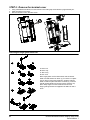
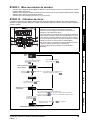
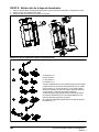
STEP 6: Remove the terminal cover
1. Using a flat bladed screwdriver, turn the terminal cover locking clip anti-clockwise by approximately 30°.
2. Slide the terminal cover down.
3. Remove terminal cover in direction shown.
Removing the finger-guard break-outs
1
2
3
A
1
2
2
1
2
1
2
1
2
1
3
2
B
C
D
A: Size 5 to 9
B: Size 5 only
C: Size 6 only
D: Size 7 to 9
Place finger-guard on a flat solid surface and hit relevant
break-outs with hammer as shown (1). For sizes 7 to 9 pliers
can be used to remove the break-outs, grasp the relevant
break-out with the pliers and twist it as shown (3). Continue
until all required break-outs are removed (2). Remove any
flash / sharp edges once the break-outs are removed.
Finger guard grommets are supplied in the kitbox for size 5
and 6.

Unidrive M200/M201/M300 Step By Step Guide 7
Issue Number: 1
English
Français Deutsch Italiano Español
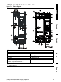
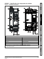
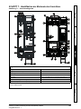
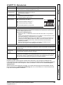
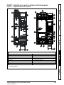
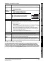
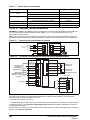
STEP 7: Identify the features of the drive
Figure 7-1 Feature diagram
PE
+DC -DC
U
V
W
L1 L2 L3
6
5
5
1
41 42
2
3
4
7
7
8
9
+DC
BRAKE
8
10
11
13
7 8
9
12
5
1
2
7
U V W
5
12
12
12 12
910
8
12
1
1
2
3
13
11
4
5
6
7
6
5
Key
1. Rating label 2. Relay connections
3. Option module slot 1 4. Motor connections
5. Ground connections 6. AC supply connections
7. Control connections 8. DC bus +
9. DC bus - 10. Braking terminal
11. Cable bracket to ground terminals
12. Internal EMC filter screw
*
13. Safe Torque Off terminals (STO)**
*
Before removing the screw, refer to Chapter 4 in the Power Installation Guide.
** Unidrive M300 only.

8 Unidrive M200/M201/M300 Step By Step Guide
Issue Number: 1
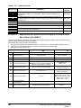
Table 7-1 Recommended torque settings
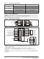
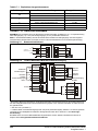
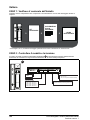
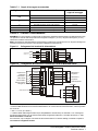
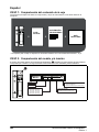
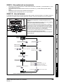
STEP 8: Wire the drive up
M200/M300: The wiring diagram is for use with the default drive configuration (Pr 05 set to AV) which is frequency
control via Analog Input 1 (0-10 V) or Analog Input 2 (0-10 V) selected by terminal 14.
M201: The default setting uses the onboard Speed Ref Potentiometer rather than the analog input for the frequency
reference (only the drive enable terminal is required).
Figure 8-1 Power terminal connections
Figure 8-2 Unidrive M200/M201/M300 control terminal connections
* Not required on Unidrive M201 since the Speed Ref Potentiometer is already on the product. The Run/Stop
commands are given from the keypad and if reverse direction is needed, the user should set Pr 17 to On.
** 250 Vac maximum (UL class 1).
*** Unidrive M300 uses Safe Torque Off (drive enable) inputs and terminal 11 is unassigned.
Refer to section 4.1 in the Control Quick Start Guide for information and wiring diagrams for alternative
configurations.
An external braking resistor can be connected if required. Refer to Chapter 4 in the Power Installation Guide for
further details.
Model size Terminal description Torque settings
All
Control terminals 0.2 N m (0.15 lb ft)
Relay terminals 0.5 N m (0.37 lb ft)
5
Power terminals 1.5 N m (1.1 lb ft)
Ground terminals 2.0 N m (1.4 lb ft)
6 Power and ground terminals 6.0 N m (4.4 lb ft)
7 Power and ground terminals 12 N m (8.85 lb ft)
8 and 9 Power and ground terminals 15 N m (11.1 lb ft)
L1
L2
L3
3 ph
AC power
supply
U
V
W
AC supply Motor
Drive enable***
9
10
11
12
Zero frequency
Run forward
*
13
Run reverse*
14
Digital I/O
Analog input 1/
Analog input 2 select
*
Digital Input 2
24 V user
Digital I/O1
Digital input 3
Digital input 4
Digital input 5
41
42
Drive ok
Relay 1**
1
2
0V
Analog I/O
Analog input 1
7
Analog output 1
4
10 V user
5
Analog input 2
Frequency
reference 1
*
Frequency
reference 2
*
Frequency output
10 kW
10 kW
31
32
35
36
S01T
0V
STO1
0V
STO2
S02T
M300 only
Safe Torque
Off
0V
24 V user

Unidrive M200/M201/M300 Step By Step Guide 9
Issue Number: 1
English
Français Deutsch Italiano Español
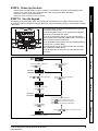
STEP 9: Power up the drive
• Ensure the drive enable signal is not given, terminal 11 (or terminal 31 and 35 on Unidrive M300) is open.
• Ensure the run signal is not given, terminal 12 and 13 are open (Unidrive M200 and M300).
• Ensure the motor is connected to the drive.
• Ensure the motor connection (Δ or Y) is correct.
STEP 10: Use the keypad
The display provides information to the user regarding the operating status of the drive, alarms and trip codes.
The keypad provides the means for changing parameters, stopping and starting the drive, and the ability to perform
a drive reset.
1
V A Hz rpm %
4
1
2
3
5
6
7
(1) The Enter button is used to enter parameter view or edit mode,
or to accept a parameter edit.
(2 / 6) The Navigation buttons can be used to select individual
parameters or to edit parameter values.
(3) The Stop / Reset button (red) is used to stop and reset the
drive in keypad mode (enabled for Unidrive M201). It can also be
used to reset the drive in terminal mode.
(4) The Speed Ref Potentiometer is used to control the frequency
reference (only on Unidrive M201).
(5) The Start button (green) is used to start the drive in keypad
mode (enabled for Unidrive M201).
(7) The Escape button is used to exit from the parameter edit /
view mode.
To return to Status Mode,
press button
To return to Parameter View Mode,
press button
Press or to select parameter
Status
Mode
To enter Parameter View Mode,
press button
Parameter
View Mode
Pr 10
Pr 01
0.00
0.00
To view parameter value
press button
To enter Edit Mode,
press button
0.00
Edit Mode (edited digit flashes)
Holding or increases or decreases value
Parameter
Value View
To return to Parameter Value View
press button to keep the new value
press
button to ignore new value and
return the parameter to the pre-edited value

10 Unidrive M200/M201/M300 Step By Step Guide
Issue Number: 1
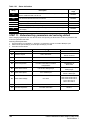
Table 10-1 Status indications
STEP 11: Understand key parameters and restoring default
When changing a parameter, the new value is saved when pressing the Enter button to return to parameter view
mode from parameter edit mode.
Restoring default parameters:
1. Ensure the drive is not enabled, i.e. terminal 11 (or terminal 31 and 35 on Unidrive M300) is open.
2. Select 'Def.50 (50 Hz settings) or Def.60 (60 Hz settings)’ in Pr 00.
3. Press the red reset button
String Description
Drive output
stage
inh
The drive is inhibited and cannot be run. The Drive Enable signal is not applied to
the drive enable terminal or is set to 0.
Disabled
rdy
The drive is ready to run. The drive enable is active, but the drive inverter is not
active because the final drive run is not active
Disabled
StoP The drive is stopped / holding zero speed. Enabled
S.Loss Supply loss condition has been detected Enabled
dc inj The drive is applying dc injection braking Enabled
Er
The drive has tripped and no longer controlling the motor. The trip code appears
on the display.
Disabled
UV The drive is in the under voltage state. Disabled
Parameter Range (Ú) Default (Ö)
01 Minimum Speed 0.00 to Pr 02 Hz 0.00 Hz
02 Maximum Speed 0.00 to 550.00 Hz
Def.50: 50.00 Hz
Def.60: 60.00 Hz
03 Acceleration Rate 1 0.0 to 32000.0 s/100 Hz 5.0 s/100 Hz
04 Deceleration Rate 1 0.0 to 32000.0 s/100 Hz 10.0 s/100 Hz
05 Drive Configuration
Refer to the Control Quick Start Guide
for further information on all drive
configurations
M200/M300: AV
M201: PAd
06 Motor Rated Current 0.00 to Drive Rating Amps
Maximum Heavy Duty
Rating Amps
07 Motor Rated Speed 0.0 to 33000.0 rpm
Def.50: 1500.0 rpm
Def.60: 1800.0 rpm
08 Motor Rated Voltage 0 to 765 V
200V drive: 230 V
400V drive Def.50: 400 V
400V drive Def.60: 460 V
575 V drive: 575 V
690 V drive: 690 V
09 Motor Rated Power Factor 0.00 to 1.00 0.85
10 User Security Status
Refer to the Control Quick Start Guide
for further information
LEVEL.1

Unidrive M200/M201/M300 Step By Step Guide 11
Issue Number: 1
English
Français Deutsch Italiano Español
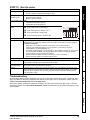
STEP 12: Run the motor
Troubleshooting
When the drive detects a fault it will display an error code. To locate and solve all error codes, a ‘Diagnostic Tool
(App)’ is available on Microsoft, Android and iOS platform via the ‘Apps’ store on Smartphone / Tablet, search for
‘Control Techniques diagnostics tool in the Apps store’.
Alternatively, please download the ‘Diagnostic Tool (App)’ from the Control Techniques ‘App Center’ or view the
diagnostics section in the Control Quick Start Guide available for download from the Control Techniques or Leroy
Somer website.
Action Detail
Power Up Ensure:
• The drive displays: inh (Enable terminal(s) is open)
Minimum and
maximum speed
Enter:
• Minimum speed Pr 01 (Hz)
• Maximum speed Pr 02 (Hz)
Accel and Decel rates Enter:
• Acceleration rate Pr 03 (s/100 Hz)
• Deceleration rate Pr 04 (s/100 Hz)
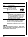
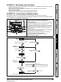
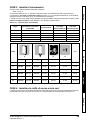
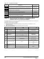
Motor nameplate
details
Ready to autotune
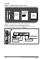
Autotune The drive is able to perform either a stationary or a rotating autotune. The motor must be at a
standstill before any autotune is enabled and disconnected from the load for a rotating autotune.
To perform an autotune:
•Set Pr38 = 1 for a stationary autotune or set Pr 38 = 2 for a rotating autotune
• Close the drive enable signal (apply +24 V to terminal 11 or terminal 31 and 35 on
Unidrive M300). The drive will display ‘rdy’.
• Give a Run command (apply +24 V to terminal 12 - Run forward or terminal 13 - Run reverse
on Unidrive M200 and M300; press keypad Start button on M201). The display will flash
‘tuning’ while the drive is performing the autotune.
• Wait for the drive to display ‘inh’ and for the motor to come to a standstill.
• Remove the drive enable and run signal from the drive.
Ready to run
Run The drive is now ready to run the motor. Close the Run Forward or Run Reverse terminals on
Unidrive M200 and M300; press keypad Start button on M201.
Increasing and
decreasing speed
Changing the selected Analog frequency reference (Speed Ref Potentiometer on M201)
will increase and decrease the speed of the motor.
Stopping To stop the motor by following the selected deceleration rate, open either the run forward or run
reverse terminal on Unidrive M200 and M300; press keypad Stop button on M201. If the enable
terminal is opened while the motor is running, the drive output is immediately disabled and the
motor will coast to a stop.
n
Motor rated current in Pr 06 (Amps)
o
Motor rated speed in Pr 07 (rpm / min
-1
)
p
Motor rated voltage in Pr 08 (Volts)
q
Motor rated power factor in (cos φ) Pr 09
MOT. 3 LS 80 L T
N
734570 BJ 002 Kg 9
40 C S1IP 55 I cl.F
V Hz min kW cos
-1
A
230 50 2800 0,75 0,83 0,3
1
2
3
4
Page is loading ...
Page is loading ...
Page is loading ...
Page is loading ...
Page is loading ...
Page is loading ...
Page is loading ...
Page is loading ...
Page is loading ...
Page is loading ...
Page is loading ...
Page is loading ...
Page is loading ...
Page is loading ...
Page is loading ...
Page is loading ...
Page is loading ...
Page is loading ...
Page is loading ...
Page is loading ...
Page is loading ...
Page is loading ...
Page is loading ...
Page is loading ...
Page is loading ...
Page is loading ...
Page is loading ...
Page is loading ...
Page is loading ...
Page is loading ...
Page is loading ...
Page is loading ...
Page is loading ...
Page is loading ...
Page is loading ...
Page is loading ...
Page is loading ...
Page is loading ...
Page is loading ...
Page is loading ...

Company information
Control Techniques Limited. Registered Office: The Gro, Newtown, Powys SY16 3BE. Registered in England
and Wales. Company Reg. No. 01236886.
Moteurs Leroy-Somer SAS. Headquarters: Bd Marcellin Leroy, CS 10015, 16915 Angoulême Cedex 9,
France.Share Capital: 65 800 512 €, RCS Angoulême 338567258.
Informations sur la société
Control Techniques Limited. Siège social : The Gro, Newtown, Powys SY16 3BE. Entreprise enregistrée en
Angleterre et au Pays de Galles N° d’immatriculation 01236886.
Moteurs Leroy-Somer SAS. Siège mondial : Bd Marcellin Leroy, CS 10015, 16915 Angoulême Cedex 9,
France. Capital social : 65 800 512 €, RCS Angoulême 338567258.
Unternehmensinformationen
Control Techniques Limited. Registrierter Sitz: The Gro, Newtown, Powys SY16 3BE. In England und Wales
registriert. Firmen-Reg. Nr. 01236886.
Moteurs Leroy-Somer SAS. Firmensitz: Bd Marcellin Leroy, CS 10015, 16915 Angoulême Cedex 9,
Frankreich. Aktienkapital: 65 800 512 €, RCS Angoulême 338567258.
Informazioni sull'azienda
Control Techniques Limited. Sede legale: The Gro, Newtown, Powys SY16 3BE. Registrata in Inghilterra e in
Galles. Numero di iscrizione al registro imprese 01236886.
Moteurs Leroy-Somer SAS. Sede centrale: Bd Marcellin Leroy, CS 10015, 16915 Angoulême Cedex 9,
Francia.Capitale sociale: 65 800 512 €, RCS Angoulême 338567258.
Información de la compañía
Control Techniques Limited. Domicilio social: The Gro, Newtown, Powys SY16 3BE. Registrada en Inglaterra
y Gales. Empresa con número de registro 01236886.
Moteurs Leroy-Somer SAS. Sede central: Bd Marcellin Leroy, CS 10015, 16915 Angoulême Cedex 9,
Francia. Capital social: 65 800 512 €, RCS Angoulême 338567258.
0478-0380-01
-
 1
1
-
 2
2
-
 3
3
-
 4
4
-
 5
5
-
 6
6
-
 7
7
-
 8
8
-
 9
9
-
 10
10
-
 11
11
-
 12
12
-
 13
13
-
 14
14
-
 15
15
-
 16
16
-
 17
17
-
 18
18
-
 19
19
-
 20
20
-
 21
21
-
 22
22
-
 23
23
-
 24
24
-
 25
25
-
 26
26
-
 27
27
-
 28
28
-
 29
29
-
 30
30
-
 31
31
-
 32
32
-
 33
33
-
 34
34
-
 35
35
-
 36
36
-
 37
37
-
 38
38
-
 39
39
-
 40
40
-
 41
41
-
 42
42
-
 43
43
-
 44
44
-
 45
45
-
 46
46
-
 47
47
-
 48
48
-
 49
49
-
 50
50
-
 51
51
-
 52
52


Control Techniques Unidrive M200 Step-By-Step Manual
- Type
- Step-By-Step Manual
- This manual is also suitable for
Ask a question and I''ll find the answer in the document
Finding information in a document is now easier with AI
in other languages
- italiano: Control Techniques Unidrive M200
- français: Control Techniques Unidrive M200
- español: Control Techniques Unidrive M200
- Deutsch: Control Techniques Unidrive M200
Related papers
Other documents
-
NGS NGS-BUNDLE-0114 Datasheet
-
Digi M200 User guide
-
Haier M300 User manual
-
TOA YP-M201 User manual
-
Optimus YP-M201 User manual
-
Polar Electro M200 User manual
-
Polar M200 User manual
-
Nidec Unidrive M100 Quick Start Manuals
-
Leroy-Somer unidrive sp Installation And Commissioning Manual
-
Polar M200 BLACK Owner's manual