Cisco Systems CIVS-IPC-2500 User manual
- Category
- Security cameras
- Type
- User manual
This manual is also suitable for


NOTICE. ALL STATEMENTS, INFORMATION, AND RECOMMENDATIONS IN THIS MANUAL ARE BELIEVED TO BE ACCURATE BUT ARE PRESENTED
WITHOUT WARRANTY OF ANY KIND, EXPRESS OR IMPLIED. USERS MUST TAKE FULL RESPONSIBILITY FOR THEIR APPLICATION OF ANY PRODUCTS.
THE SOFTWARE LICENSE AND LIMITED WARRANTY FOR THE ACCOMPANYING PRODUCT ARE SET FORTH IN THE INFORMATION PACKET THAT
SHIPPED WITH THE PRODUCT AND ARE INCORPORATED HEREIN BY THIS REFERENCE. IF YOU ARE UNABLE TO LOCATE THE SOFTWARE LICENSE
OR LIMITED WARRANTY, CONTACT YOUR CISCO REPRESENTATIVE FOR A COPY.
The Cisco implementation of TCP header compression is an adaptation of a program developed by the University of California, Berkeley (UCB) as part of UCB’s public
domain version of the UNIX operating system. All rights reserved. Copyright © 1981, Regents of the University of California.
NOTWITHSTANDING ANY OTHER WARRANTY HEREIN, ALL DOCUMENT FILES AND SOFTWARE OF THESE SUPPLIERS ARE PROVIDED “AS IS” WITH
ALL FAULTS. CISCO AND THE ABOVE-NAMED SUPPLIERS DISCLAIM ALL WARRANTIES, EXPRESSED OR IMPLIED, INCLUDING, WITHOUT
LIMITATION, THOSE OF MERCHANTABILITY, FITNESS FOR A PARTICULAR PURPOSE AND NONINFRINGEMENT OR ARISING FROM A COURSE OF
DEALING, USAGE, OR TRADE PRACTICE.
IN NO EVENT SHALL CISCO OR ITS SUPPLIERS BE LIABLE FOR ANY INDIRECT, SPECIAL, CONSEQUENTIAL, OR INCIDENTAL DAMAGES, INCLUDING,
WITHOUT LIMITATION, LOST PROFITS OR LOSS OR DAMAGE TO DATA ARISING OUT OF THE USE OR INABILITY TO USE THIS MANUAL, EVEN IF CISCO
OR ITS SUPPLIERS HAVE BEEN ADVISED OF THE POSSIBILITY OF SUCH DAMAGES.
CCDE, CCENT, Cisco Eos, Cisco Lumin, Cisco StadiumVision, the Cisco logo, DCE, and Welcome to the Human Network are trademarks; Changing the Way We Work,
Live, Play, and Learn is a service mark; and Access Registrar, Aironet, AsyncOS, Bringing the Meeting To You, Catalyst, CCDA, CCDP, CCIE, CCIP, CCNA, CCNP, CCSP,
CCVP, Cisco, the Cisco Certified Internetwork Expert logo, Cisco IOS, Cisco Press, Cisco Systems, Cisco Systems Capital, the Cisco Systems logo, Cisco Unity,
Collaboration Without Limitation, EtherFast, EtherSwitch, Event Center, Fast Step, Follow Me Browsing, FormShare, GigaDrive, HomeLink, Internet Quotient, IOS, iPhone,
iQ Expertise, the iQ logo, iQ Net Readiness Scorecard, iQuick Study, IronPort, the IronPort logo, LightStream, Linksys, MediaTone, MeetingPlace, MGX, Networkers,
Networking Academy, Network Registrar, PCNow, PIX, PowerPanels, ProConnect, ScriptShare, SenderBase, SMARTnet, Spectrum Expert, StackWise, The Fastest Way to
Increase Your Internet Quotient, TransPath, WebEx, and the WebEx logo are registered trademarks of Cisco Systems, Inc. and/or its affiliates in the United States and certain
other countries.
All other trademarks mentioned in this document or Website are the property of their respective owners. The use of the word partner does not imply a partnership relationship
between Cisco and any other company. (0804R)
Cisco Video Surveillance System IP Camera User Guide
Copyright © 2008 Cisco Systems, Inc. All rights reserved.

iii
Cisco Video Surveillance System IP Camera User Guide
OL-14220-01
CONTENTS
Preface v
Overview v
Organization v
Obtaining Documentation, Obtaining Support, and Security Guidelines v
CHAPTER
1 Overview 1-1
IP Camera Features 1-1
IP Camera Physical Details 1-2
DC Auto Iris Lens Connector Pinouts 1-6
Package Contents 1-6
CHAPTER
2 Getting Started 2-1
Installing the IP Camera 2-1
Performing the Initial Setup of the IP Camera 2-4
Accessing the IP Camera Windows 2-5
Adjusting Back Focus on the IP Camera 2-7
Powering the IP Camera On or Off 2-7
Resetting the IP Camera 2-8
CHAPTER
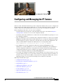
3 Configuring and Managing the IP Camera 3-1
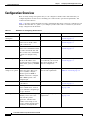
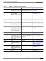
Configuration Overview 3-2
Navigating the Configuration Windows 3-4
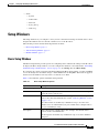
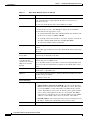
Setup Windows 3-5
Basic Setup Window 3-5
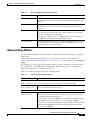
Advanced Setup Window 3-7
IP Filter Window 3-9
Administration Windows 3-10
Users Window 3-10
Maintenance Window 3-12
Firmware Window 3-13
Audio/Video Windows 3-14

Contents
iv
Cisco Video Surveillance System IP Camera User Guide
OL-14220-01
Video Window 3-14
Audio Window 3-17
Security Windows 3-18
Product Process Window 3-19
Initialization Window 3-19
Complexity Window 3-20
Applications Windows 3-20
Mail & FTP Window 3-21
Motion Detection Window 3-23
Event Window 3-24
SNMP Window 3-26
Alarm I/O Ports Window 3-27
PTZ (RS-485) Window 3-28
Preset Positions Window 3-30
Status Windows 3-31
System Window 3-32
Audio/Video Window 3-32
Network Window 3-33
Syslog & Log Window 3-34
Video Log Window 3-37
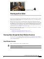
CHAPTER
4 Viewing and Live Video 4-1
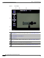
Viewing Video through the Home Window Overview 4-1
Home Window Overview 4-1
Home Window Controls 4-3
Viewing Video through Third-Party Devices or Software 4-6
CHAPTER
5 Troubleshooting 5-1
APPENDIX
A Using the IP Camera with Cisco VSM A-1
Obtaining the Required Driver Pack A-2
Guidelines for Using the IP Camera with VSM A-2
Troubleshooting the IP Camera when used with VSM A-3
I
NDEX

v
Cisco Video Surveillance System IP Camera User Guide
OL-14220-01
Preface
Overview
This document, Cisco Video Surveillance IP Camera User Guide provides information about installing,
configuring, using, managing, and troubleshooting the Cisco Video Surveillance IP Camera model
CIVS-IPC-2500.
Organization
This manual is organized as follows:
Obtaining Documentation, Obtaining Support, and Security
Guidelines
For information about obtaining documentation, submitting a service request, and gathering additional
information, see the monthly What’s New in Cisco Product Documentation, which also lists all new and
revised Cisco technical documentation, at:
http://www.cisco.com/en/US/docs/general/whatsnew/whatsnew.html
Chapter 1, “Overview” Provides an overview of the IP camera and its features
Chapter 2, “Getting Started” Provides instructions for installing and performing
the initial setup of the IP camera, connecting to the IP
camera so that you can configure it or view video
from it, powering the IP camera on and off, resetting
the IP camera, and adjusting its back focus
Chapter 3, “Configuring and Managing the IP
Camera”
Explains how to configure, manage, and administer
the IP camera through the web-based interface
Chapter 4, “Viewing and Live Video” Explains how to view live video from the IP camera
Chapter 5, “Troubleshooting” Provides basic troubleshooting information
Appendix A, “Using the IP Camera with Cisco
VSM”
Provides information that applies when you use the IP
camera with Cisco Video Surveillance Manager
(VSM)

vi
Cisco Video Surveillance System IP Camera User Guide
OL-14220-01
Preface
Obtaining Documentation, Obtaining Support, and Security Guidelines
Subscribe to the What’s New in Cisco Product Documentation as a Really Simple Syndication (RSS) feed
and set content to be delivered directly to your desktop using a reader application. The RSS feeds are a free
service and Cisco currently supports RSS version 2.0.

CHAPTER
1-1
Cisco Video Surveillance System IP Camera User Guide
OL-14220-01
1
Overview
This chapter provides an overview of the Cisco Video Surveillance IP Camera and its features. It
includes these topics:
• IP Camera Features, page 1-1
• IP Camera Physical Details, page 1-2
• DC Auto Iris Lens Connector Pinouts, page 1-6
• Package Contents, page 1-6
Note If you use the IP camera with Cisco Video Surveillance Manager (VSM), not all IP camera features are
currently supported. These features are noted throughout this manual. For more detailed information,
including usage guidelines and troubleshooting tips, see Appendix A, “Using the IP Camera with Cisco
VSM.”
IP Camera Features
The Cisco Video Surveillance IP Camera offers a feature-rich digital camera solution for a video
surveillance system. It provides high-quality, bandwidth-efficient video capture and transmission, with
support for D1 resolution, motion-triggered viewing, and MPEG-4 encoding. It can be powered through
an external power supply or by integrated Power over Ethernet (PoE).
In addition, the IP camera provides networking and security capabilities, including multicast support,
hardware-based Advanced Encryption Standard (AES), and hardware-based Data Encryption
Standard/Triple Data Encryption Standard (DES/3DES) encryption.
The IP camera includes the following key features:
• Built-in MPEG4 encoder—An internal MPEG4 encoder can generate up to two video streams.
• Day/night switch support—An IR-cut filter provides increased sensitivity in low-light conditions.
• Two-way audio communication—Audio can be encoded with the video. With the internal or
optional external microphone and optional external speaker, you can communicate with people at
the IP camera location while you are in a remote location and viewing images from the IP camera.
• Multi-protocol support—Supp ort s th ese pro toco ls : D HC P, FT P, HTT P, HT TPS , NT P, RT P, RT SP,
SMTP, SSL/TLS, and TCP/IP.
• Web-based management—You perform ongoing administration and management of the IP camera
through web-based configuration menus.

1-2
Cisco Video Surveillance System IP Camera User Guide
OL-14220-01
Chapter 1 Overview
IP Camera Physical Details
• Motion detection—The IP camera can detect motion in up to three designated fields of view by
analyzing changes in pixels and generate an alert if motion is detected.
• Flexible scheduling—You can configure the IP camera to respond to events that occur within a
designated schedule.
• Syslog support—The IP camera can send log data to a Syslog server.
• IP address filter—You can designate IP addresses that can access the IP camera and IP addresses
that cannot access the IP camera.
• User-definable HTTP/ HTTPS port number—Allows you to define the port that is used to
connect to the camera through the Internet.
• DHCP support—The IP camera can automatically obtain its IP addresses in a network in which
DHCP is enabled.
• Network Time Protocol (NTP) support—Allows the IP camera to calibrate its internal clock with
a local or Internet time server.
• Support for C and CS mount lenses—The IP camera supports a variety of C and CS mount lenses.
• RS-485/PTZ support—The IP camera supports Pelco D protocol, which enables PTZ functions
when used with a supported motorized zoom lens, external pan/tilt mount, and control device.
• Power options—The wired IP camera model can be powered with 12 volts DC, which is provided
through an optional external power adapter, or through PoE (802.3af), which is provided through a
supported switch.
• Camera access control—You can control access to IP camera configuration windows and live video
by configuring various user types and log in credentials.
IP Camera Physical Details
The IP camera includes a reset button, built-in microphone, status LEDs, several ports for connecting
external devices, and two threaded mounting holes, one on the bottom and one on the top.
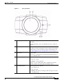
Figure 1-1 and the table that follows describe the items on the front of the IP camera.

1-3
Cisco Video Surveillance System IP Camera User Guide
OL-14220-01
Chapter 1 Overview
IP Camera Physical Details
Figure 1-1 Front of IP Camera
1 Lens opening The IP camera supports a variety of C and CS mount lenses, which
attach here.
For best performance, Cisco recommends that you use a DC auto
iris lens.
2 Focus ring Allows you to adjust the back focus of the IP camera.
You must loosen the focus ring hex screw on the bottom of the IP
camera before you can rotate the focus ring. For instructions, see
the “Adjusting Back Focus on the IP Camera” section on page 2-7.
3 Microphone Captures audio.
There also is a connection for an optional external microphone on
the rear of the IP camera.
4 Activity LED (green) Indicates activity as follows:
• Off—No activity.
• Blinking—Activity detected.
Activity can occur when the IP camera communicates with the
network or when a user views video from the IP camera.
5 Ready LED (amber) Indicates power state as follows:
• On—Power is on.
• Off—No power.
• Blinking—IP camera is starting up. The start up process takes
15 to 20 seconds.

1-4
Cisco Video Surveillance System IP Camera User Guide
OL-14220-01
Chapter 1 Overview
IP Camera Physical Details
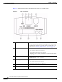
Figure 1-2 and the table that follows describe the items on the rear of the IP camera.
Figure 1-2 Rear of IP Camera
1 Reset button Recessed button that reboots the IP camera or resets it to a default
state. You can use a pin or paper clip to depress it. It can be used
any time that the IP camera is on and can have various effects, as
described in the “Resetting the IP Camera” section on page 2-8.
2 Network LED (amber) Indicates information about the network connections as follows:
• On—LAN connection is detected
• Off—LAN connection is not detected
• Blinking—Data is being transmitted or received via the LAN
connection
3 LAN port Accepts a standard LAN cable to connect the IP camera to a
10/100BASET hub, router, or switch.
4 PoE LED (green) Indicates information about PoE as follows:
• On—PoE connection is detected
• Off—PoE connection is not detected
5 Analog video output BNC connector for video output (75 ohm).
6 Speaker output Allows the connection of an optional external speaker through a
standard 3.5 mm mini phone jack.

1-5
Cisco Video Surveillance System IP Camera User Guide
OL-14220-01
Chapter 1 Overview
IP Camera Physical Details
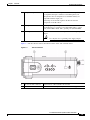
Figure 1-3 and the table that follows describe the items on the side of the IP camera.
Figure 1-3 Side of IP Camera
7 Microphone input Allows the connection of an optional external microphone (with
pre-amplifier) through a standard 3.5 mm mini phone jack.
Microphones that are designed for use with PCs usually are
compatible with this input jack.
Connecting an external microphone disables the internal
microphone on the IP camera.
8 GPIO ports General purpose input/output (GPIO) terminal block that includes
a 2-pin RS-485 port, 2 input ports (labeled DI1, DI2), 2 output
ports (labeled DO1, DO2), and 3 ground ports (labeled GND).
9 Power input Provides for the connection of an optional 12 V, 1 amp DC power
adapter.
Caution Use only the Cisco specified power supply adapter.
1 DC auto iris lens connector Connection for cable from DC auto iris lens
2 Lockdown cable slot Connection for Kensington-compatible lockdown equipment

1-6
Cisco Video Surveillance System IP Camera User Guide
OL-14220-01
Chapter 1 Overview
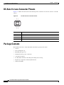
DC Auto Iris Lens Connector Pinouts
DC Auto Iris Lens Connector Pinouts
Figure 1-4 and the table that follows describe the pinouts of the DC auto iris lens connector on the IP
camera.
Figure 1-4 DC Auto Iris Lens Connector Pinouts
Package Contents
The includes in the Cisco Video Surveillance IP Camera package these items:
• Camera
• Lens opening dust cap
• Mounting hole protector
• Terminal block for power connection
• C mount lens adaptor
• 0.9 mm Allen wrench for unlocking and locking the focus ring
• Regulatory Compliance and Safety Information
• Quick Start Guide
Pin Function
1Damp –
2Damp +
3Drive +
4Drive –

CHAPTER
2-1
Cisco Video Surveillance System IP Camera User Guide
OL-14220-01
2
Getting Started
This chapter provides instructions for installing and performing the initial setup of the Cisco Video
Surveillance IP Camera. It also describes how to access the IP camera through a web browser so that you
can configure it or view video from it, and how to perform other important tasks.
This chapter includes these topics:
• Installing the IP Camera, page 2-1
• Performing the Initial Setup of the IP Camera, page 2-4
• Accessing the IP Camera Windows, page 2-5
• Adjusting Back Focus on the IP Camera, page 2-7
• Powering the IP Camera On or Off, page 2-7
• Resetting the IP Camera, page 2-8
Installing the IP Camera
This section describes how to install the IP camera. Before installing, review these guidelines:
• The IP camera requires a network cable and a connection to a standard 10/100BaseT hub, router, or
switch. To power the IP camera with Power over Ethernet (PoE), a switch must be 802.3af
compliant.
• If you are using the IP camera on a network connection that does not provide PoE, you must use the
Cisco 12 V power adapter (Cisco part number CIVS-PWRPAC-12V). You can order the power
adapter from Cisco.
• If you are using an external speaker, microphone, input device, output device, or control device, you
must configure additional settings after installing and performing the initial set up of the IP camera
before the external device can fully operate. For detailed information about these settings, see
Chapter 3, “Configuring and Managing the IP Camera.”
• If you do not connect an external device (speaker, microphone, analog video display, input device,
output device, or control device) when you perform the following installation procedure, you can
install any of these devices later.
Warning
Installation of the equipment must comply with local and national electrical codes.
Statement 1074

2-2
Cisco Video Surveillance System IP Camera User Guide
OL-14220-01
Chapter 2 Getting Started
Installing the IP Camera
Warning
The power supply must be placed indoors.
Statement 331
Note If you use the IP camera outdoors, place the camera and the power supply in a suitable NEMA
enclosure.
Warning
This product requires short-circuit (overcurrent) protection, to be provided as part of the building
installation. Install only in accordance with national and local wiring regulations.
Statement 1045
Warning
This product must be connected to a power-over-ethernet (PoE) IEEE 802.3af compliant power source
or an IEC60950 compliant limited power source.
Statement 353
Warning
The plug-socket combination must be accessible at all times, because it serves as the main
disconnecting device.
Statement 1019
Caution Inline power circuits provide current through the communication cable. Use the Cisco provided cable or
a minimum 24AWG communication cable
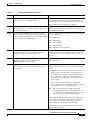
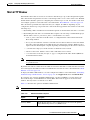
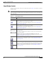
To install the IP camera, follow the steps in Table 2-1. For illustrations of the connectors and ports that
the steps refer to, see the “IP Camera Physical Details” section on page 1-2.
.
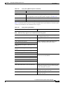
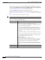
Table 2-1 Installing the IP Camera
Action Explanation
Step 1
Attach a lens to the lens opening on the IP camera. • If you are using a CS mount lens, screw the lens into
the lens opening. The IP camera accepts CS-mount
lenses with a lens protrusion of up to 5 mm.
• If you are using a C mount lens, screw the C mount
lens adapter that is supplied with the IP camera into
the lens opening, then screw the lens into the adapter.
Ensure that the lens is clean because any dirt may degrade
the quality of video images.
Note Save the lens opening dust cap and replace the dust
cap if you remove the lens.
Step 2
If you are using a DC auto iris lens, connect its cable to
the DC auto iris lens connector on the IP camera.
For best performance, Cisco recommends that you use a
DC auto iris lens.
Step 3
Optional. Connect a speaker to the speaker output jack
on the rear of the IP camera.
A speaker plays audio that is captured by a microphone
that is attached to the PC on which you view video from
the camera.

2-3
Cisco Video Surveillance System IP Camera User Guide
OL-14220-01
Chapter 2 Getting Started
Installing the IP Camera
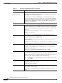
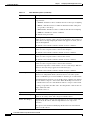
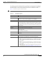
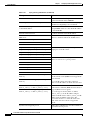
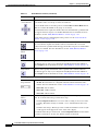
Step 4
Optional. Connect a microphone to the microphone
input jack on the rear of the IP camera.
Connecting an external microphone disables the IP camera
internal microphone. Place the external microphone in a
location that allows it to capture the audio that you want.
The microphone must include a pre-amplifier.
Step 5
Optional. Connect an NTSC or PAL compliant analog
video display device to the video output connector on
the rear of the IP camera.
This device displays video from the IP camera. The
display does not include the time stamp or text that are
configured for the camera.
Step 6
Optional. Use the GPIO ports on the rear of the IP
camera to connect external devices that trigger alarms
(connect through alarm input ports) or respond to alarms
(connect through alarm output ports).
You can connect up to two input devices and two output
devices to these ports:
DI1—Alarm input 1
DI2—Alarm input 2
DO1—Alarm output 1
DO2—Alarm output 2
GND—Ground (for use if needed)
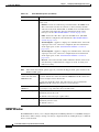
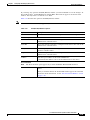
Step 7
Optional. Use the RS485 GPIO ports on the rear of the
IP camera to connect a control device (motorized
housing) that supports the Pelco D protocol.
These ports are labeled D+ (data plus) and D– (data
minus) and accept a cable with two conductors. The cable
fits into the ports in one way. Make sure to insert it
properly.
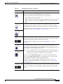
Step 8
Connect a category 5 or higher network cable to the
LAN port on the back of the camera and to a
10/100BaseT hub, router, or switch.
If your network provides PoE, the IP camera powers on.
Skip to Step 10.
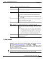
Step 9
If you are using the IP camera on a network connection
that does not provide PoE, connect the optional 12 V
power adapter.
First, connect the bare wires at the end of the power
adapter to the terminal block that is provided with the IP
camera:
• With the screws on the terminal block facing down,
put the positive wire into the slot at the right rear of
the terminal block and put the negative wire into the
slot on the left. (On the Cisco power adapter, the
positive wire has a white stripe and the negative wire
has no stripe.)
• Use a small flat-head screwdriver to tighten the
screws on the bottom of the terminal block so that the
power adapter wires are attached securely.
Note The power adapter may include an attached
terminal block that does not fit the IP camera. If
so, remove that terminal block and replace it with
the one that is provided with the IP camera.
Next, plug the terminal block into the power input port on
back of the IP camera. The terminal block fits into the
input port in one way. Make sure that the tabs on the
terminal block face the bottom of the IP camera.
Finally, plug the power adapter into an electrical outlet.
The IP camera powers up.
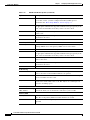
Table 2-1 Installing the IP Camera (continued)
Action Explanation

2-4
Cisco Video Surveillance System IP Camera User Guide
OL-14220-01
Chapter 2 Getting Started
Performing the Initial Setup of the IP Camera
After you install the IP camera, follow the instructions in the “Performing the Initial Setup of the IP
Camera” section on page 2-4 to access and configure the camera.
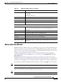
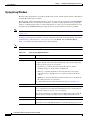
Performing the Initial Setup of the IP Camera
After you install IP camera as described in the “Installing the IP Camera” section on page 2-1, or after
you perform a factory reset procedure, you must access the IP camera and make initial configuration
settings. These settings include administrator and root passwords, and whether the IP camera can be
accessed through an HTTP connection in addition to the default HTTPS (HTTP secure) connection.
To make these configuration settings, you connect to the IP camera from any PC that is on the same
network as the IP camera. The PC must meet these requirements:
• Operating system—Microsoft Windows 2000, XP, or Vista
• Browser—Internet Explorer 6.x with Service Pack 2, or later
In addition, you must know the IP address of the IP camera. By default, when the IP camera powers on,
it attempts to obtain an IP address from a DHCP server in your network. If the camera cannot obtain an
IP address through DCHP within 90 seconds, it uses a default IP address of 192.168.0.100.
To connect to the IP camera for the first time and make initial configuration settings, perform the
following steps. You can change these configuration settings in the future as described in the
“Initialization Window” section on page 3-19.
Procedure
Step 1 Start Internet Explorer, enter HTTPS://ip_a ddress in the address field, and press Enter.
Replace ip_address with the IP address that the IP camera obtained through DHCP or, if the camera was
unable to obtain this IP address, enter 192.168.0.100.
The Account window appears.
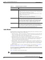
Step 10
Check the LEDs on the IP camera.
• The Ready LED blinks while the IP camera starts up.
After 15 to 20 seconds, startup completes and the
Ready LED should remain on.
• The Network LED should be on.
Step 11
Mount the IP camera in the desired location. Connect the mounting device to the threaded mounting
hole on the bottom or top of the IP camera, depending on
your installation requirement.
You may first need to remove the rubber protector from the
mounting hole. Place this protector in the unused
mounting hole.
Step 12
Optional. Use the lockdown cable slot to secure the IP
camera.
You can secure the IP camera to a fixed object by using
Kensington-compatible lockdown equipment
Table 2-1 Installing the IP Camera (continued)
Action Explanation

2-5
Cisco Video Surveillance System IP Camera User Guide
OL-14220-01
Chapter 2 Getting Started
Accessing the IP Camera Windows
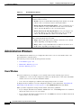
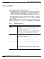
Step 2 In the Set Password and Verify Password fields in the Admin column, enter a password for the IP camera
administrator.
You must enter the same password in both fields. The password is case sensitive and must contain at least
eight characters, which can be letters, numbers, and special characters, but no spaces. Special characters
are: ! " # $ % & ' ( ) * + , - . : ; < = > ? @ [ \ ] ^ _ ` { | } ~.
Step 3 In the Set Password and Verify Password fields in the Root column, enter a password that is used when
accessing the IP camera through a Secure Shell (SSH) connection.
You must enter the same password in both fields. The password is case sensitive and must contain at least
eight characters, which can be letters, numbers, and special characters, but no spaces. Special characters
are: ! " # $ % & ' ( ) * + , - . : ; < = > ? @ [ \ ] ^ _ ` { | } ~.
You use the root password if you need to troubleshoot the IP camera through a SSH connection with the
assistance of the Cisco Technical Assistance Center.
Step 4 In the HTTP area, click the HTTP radio button if you want to allow both HTTP and HTTPS connections
to the IP camera.
The default setting is HTTPS, which allows only HTTPS (secure) connections to the IP camera.
Step 5 Click Apply.
The IP camera reboots.
Step 6 After the IP camera reboots, start Internet Explorer and, in the Address field, enter the following:
protocol ://192.168.0.100
where protocol is HTTPS or HTTP. (You can use HTTP only if you enabled it in Step 4.)
Step 7 If you are prompted to install ActiveX controls, which are required to view video from the IP camera,
follow the on-screen prompts to do so.
The Main window appears and video from the IP camera starts playing automatically.
You can take these actions in the Main window:
• Click the Setup link to access configuration menus for the camera. For detailed information about
these menus, see Chapter 3, “Configuring and Managing the IP Camera.”
• Click the Home link to view and control live video from the camera. For detailed information about
these actions, see Chapter 4, “Viewing and Live Video.”
• Click the Logout button to exit the window.
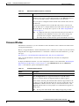
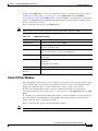
Accessing the IP Camera Windows
After you perform the initial configuration as described in the “Performing the Initial Setup of the IP
Camera” section on page 2-4, follow the steps in this section each time that you want to access the IP
camera windows to make configuration settings or view live video.
You access these windows by connecting to the IP camera from any PC that is on the same network as
the IP camera and that meets these requirements:
• Operating system—Microsoft Windows 2000, Windows XP, or Vista
• Browser—Internet Explorer 6.x with Service Pack 2, or later

2-6
Cisco Video Surveillance System IP Camera User Guide
OL-14220-01
Chapter 2 Getting Started
Accessing the IP Camera Windows
You need this information to access the IP camera windows:
• IP address of the IP camera. The default IP address is 192.168.0.100.
• Port number, if other than the default value. Default port numbers for the IP camera are 443 for
HTTPS and 80 for HTTP. The IP camera administrator can enable an alternative HTTPS port and an
alternative HTTP port as described in the “Advanced Setup Window” section on page 3-7.
• Your user name and password for the IP camera. The IP camera administrator configures user names
and passwords as described in the “Users Window” section on page 3-10.
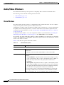
To access the IP camera windows, follow these steps:
Procedure
Step 1 Start Internet Explorer and enter the following in the address field:
protocol:/ /ip_addre ss:port _number
where:
• protocol is HTTPS for a secure connection or HTTP for a non-secure connection. You can use
HTTP only if you configure the camera to accept non-secure HTTP connections as described in the
“Performing the Initial Setup of the IP Camera” section on page 2-4.
• ip_address is the IP address of the IP camera. The default IP address is 192.168.0.100.
• port_number is the port number that is used for HTTPS or HTTP connections to the IP camera. You
do not need to enter a port number if you are connecting through the default HTTPS port 443 or the
default HTTP port 80.
For example,
• Enter the following for a secure connection if the IP address is 192.168.0.100 and the HTTPS port
number is 443:
https://192.168.0.100
• Enter the following for a secure connection if the IP address is 203.70.212.52 and the HTTPS port
number is 1024:
https://203.70.212.52:1024
• Enter the following for a non-secure connection if the IP address is 203.70.212.52 and the HTTP
port number is 80:
http://203.70.212.52
• Enter the following for a non-secure connection if the IP address is 203.70.212.52 and the HTTP
port number is 1024:
http://203.70.212.52:1024
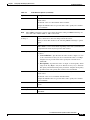
Step 2 Enter your IP camera user name and password when prompted, then click OK.
To log in as the IP camera administrator, enter the user name admin (which is case sensitive) and the
password that is configured for the administrator. To log in as a user, enter the user name and password
that are configured for the user.
Note If an administrator or user is already logged in with the user name and password that you enter,
the following message appears, where name is the IP camera user name and address is the IP
address of the PC from which the user is accessing the IP camera:
This account is currently
in use [id:
user
, ip:
address
].

2-7
Cisco Video Surveillance System IP Camera User Guide
OL-14220-01
Chapter 2 Getting Started
Adjusting Back Focus on the IP Camera
The Main window appears and video from the IP camera starts playing automatically. You can take these
actions in the Main window:
• Click the Setup link to access configuration menus for the camera. For detailed information about
these menus, see Chapter 3, “Configuring and Managing the IP Camera.”
• Click the Home link to view and control live video from the camera. For detailed information about
these actions, see Chapter 4, “Viewing and Live Video.”
• Click the Logout button to exit the window.
Adjusting Back Focus on the IP Camera
To obtain the sharpest image from the camera, you may need to adjust its back focus. This adjustment is
useful if the focus control on a lens does not allow you to obtain a sharp enough image.
To adjust the back focus, perform the following steps while viewing video from the camera. For
information about viewing video, see Chapter 4, “Viewing and Live Video.”
Procedure
Step 1 With a lens attached to the IP camera, use the 0.9mm Allen wrench that is supplied with the IP camera
to loosen the focus ring hex screw.
This screw is on the bottom of the camera just behind the focus ring.
Step 2 Adjust the back focus by aiming the IP camera at an object that is at least 15 feet (4.5 meters) away and
rotating the focus ring to obtain a clear image as follows:
• For a variable-focus lens, obtain a sharp picture in both wide-angle and telephoto positions.
• For a zoom lens, ensure that the object of interest remains in focus throughout the entire zoom range
of the lens.
Step 3 Use the Allen wrench to tighten the focus ring hex screw.
Powering the IP Camera On or Off
The IP camera does not include an on/off switch. You power it on or off by connecting it to or
disconnecting it from a power source. When you power off the IP camera, configuration settings are
retained.
To power on the IP camera, take either of these actions:
• Use a category 5 or higher network cable to connect the IP camera to a network switch that provides
802.3af compliant PoE
• Use the optional 12 V power adapter to connect the IP camera to a wall outlet
To power off the IP camera, take either of these actions:
• If the IP camera is receiving PoE, disconnect the network cable

2-8
Cisco Video Surveillance System IP Camera User Guide
OL-14220-01
Chapter 2 Getting Started
Resetting the IP Camera
• If the IP camera is receiving power through the power adapter, unplug the adapter from the wall or
disconnect it from the camera
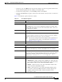
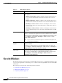
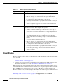
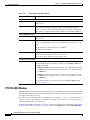
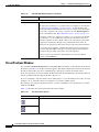
Resetting the IP Camera
You reset the IP camera by pressing the Reset button on the rear of the device (see ). There are various
reset types, as described in Table 2-2.
You also can perform some reset operations from the Maintenance window as described in the
“Maintenance Window” section on page 3-12.
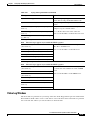
Table 2-2 Resetting the IP Camera
Reset Type Procedure Remarks
Reboot. Press and immediately release
the Reset button.
This action is equivalent to
powering the IP camera down
and then powering it up. Settings
that are configured for the IP
camera are retained.
IP address reset. Press and hold the Reset button
for at least 1 second but no more
than 9 seconds.
If DHCP is enabled in your
network, the IP camera obtains
an IP address from the DHCP
server. Otherwise, after 90
seconds, the IP camera IP
address resets to the default
address of 192.168.0.100. All
other configuration settings are
retained.
Factory reset. Press and hold the button for at
least 10 seconds.
Sets all IP camera options to
their default values. After you
perform this procedure, follow
the steps in the “Performing the
Initial Setup of the IP Camera”
section on page 2-4.
Page is loading ...
Page is loading ...
Page is loading ...
Page is loading ...
Page is loading ...
Page is loading ...
Page is loading ...
Page is loading ...
Page is loading ...
Page is loading ...
Page is loading ...
Page is loading ...
Page is loading ...
Page is loading ...
Page is loading ...
Page is loading ...
Page is loading ...
Page is loading ...
Page is loading ...
Page is loading ...
Page is loading ...
Page is loading ...
Page is loading ...
Page is loading ...
Page is loading ...
Page is loading ...
Page is loading ...
Page is loading ...
Page is loading ...
Page is loading ...
Page is loading ...
Page is loading ...
Page is loading ...
Page is loading ...
Page is loading ...
Page is loading ...
Page is loading ...
Page is loading ...
Page is loading ...
Page is loading ...
Page is loading ...
Page is loading ...
Page is loading ...
Page is loading ...
Page is loading ...
Page is loading ...
Page is loading ...
Page is loading ...
Page is loading ...
Page is loading ...
Page is loading ...
Page is loading ...
Page is loading ...
Page is loading ...
Page is loading ...
Page is loading ...
Page is loading ...
Page is loading ...
Page is loading ...
Page is loading ...
Page is loading ...
Page is loading ...
-
 1
1
-
 2
2
-
 3
3
-
 4
4
-
 5
5
-
 6
6
-
 7
7
-
 8
8
-
 9
9
-
 10
10
-
 11
11
-
 12
12
-
 13
13
-
 14
14
-
 15
15
-
 16
16
-
 17
17
-
 18
18
-
 19
19
-
 20
20
-
 21
21
-
 22
22
-
 23
23
-
 24
24
-
 25
25
-
 26
26
-
 27
27
-
 28
28
-
 29
29
-
 30
30
-
 31
31
-
 32
32
-
 33
33
-
 34
34
-
 35
35
-
 36
36
-
 37
37
-
 38
38
-
 39
39
-
 40
40
-
 41
41
-
 42
42
-
 43
43
-
 44
44
-
 45
45
-
 46
46
-
 47
47
-
 48
48
-
 49
49
-
 50
50
-
 51
51
-
 52
52
-
 53
53
-
 54
54
-
 55
55
-
 56
56
-
 57
57
-
 58
58
-
 59
59
-
 60
60
-
 61
61
-
 62
62
-
 63
63
-
 64
64
-
 65
65
-
 66
66
-
 67
67
-
 68
68
-
 69
69
-
 70
70
-
 71
71
-
 72
72
-
 73
73
-
 74
74
-
 75
75
-
 76
76
-
 77
77
-
 78
78
-
 79
79
-
 80
80
-
 81
81
-
 82
82


Cisco Systems CIVS-IPC-2500 User manual
- Category
- Security cameras
- Type
- User manual
- This manual is also suitable for
Ask a question and I''ll find the answer in the document
Finding information in a document is now easier with AI
Related papers
-
Cisco CIVS-IPC-2500 User manual
-
Cisco Systems Security Camera 4500E User manual
-
-
-
-
Cisco Video Surveillance 6000 Series IP Cameras User manual
-
-
-
-
Other documents
-
-
Cisco Video Surveillance 3520 IP Camera Configuration Guide
-
Asoni CAM713MICR User manual
-
Linksys M20 User manual
-
-
-
-
-
-