
Installation Guide
AT-HDVS-CAM-HDMI-BK and AT-HDVS-CAM-HDMI-WH
1
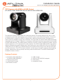
PTZ Camera with HDMI and USB Output
AT-HDVS-CAM-HDMI-BK and AT-HDVS-CAM-HDMI-WH
The Atlona AT-HDVS-CAM-HDMI is an enterprise-grade PTZ camera designed for use in video
conferencing and other applications such as lecture capture and distance education. It features
an HDMI output, as well as a USB 2.0 interface for video and camera control. Simultaneous
video output is available through two interfaces. Through USB, the HDVS-CAM-HDMI seamlessly
integrates with the Omega™ Series for a complete, automated conferencing system that includes
AV and USB extension. The HDMI output is ideal for use with a video conferencing codec, lecture
capture appliance, or PC equipped for video capture. The HDVS-CAM-HDMI delivers high perfor-
mance, professional-quality imaging with video resolutions up to 1080p @ 60 Hz over HDMI and
1080p @ 30 Hz for USB 2.0, as well as fast and accurate auto-focusing, and a fast yet quiet pan
and tilt mechanism. This PTZ camera is ideal for a wide range of small to medium-sized meeting
spaces, classrooms, training rooms, and many other environments. The HDVS-CAM-HDMI is
available in black or white.
1 x AT-HDVS-CAM-HDMI-BK or
AT-HDVS-CAM-HDMI-WH
1 x Wall mounting plate
1 x 1/4 20OUNC screws
1 x IR Remote Control
1 x USB A cable
1 x VISCA to RS-232 DB-9 adapter
2 x AAA battery
1 x Installation Guide
Package Contents

Installation Guide
AT-HDVS-CAM-HDMI-BK and AT-HDVS-CAM-HDMI-WH
2
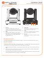
1 RS-232
Connect included VISCA to RS-232
adapter here to control the camera with a
third party software or hardware controller.
2 USB
Connect USB A cable from this port to
the USB port of a conferencing system or
USB extender such as AT-OME-EX-RX,
AT-OME-SR21, etc.
3 HDMI OUT
Connect to an HDMI device such as a
video conference codec or PC.
4 LAN
Connect to a network switch to control
the unit via TCP/IP or webGUI.
5 DC 12V
Connect the included 12V power supply
to this port.
Panel Descriptions
1
0
X
Z
o
o
m
F
1
.
6
-
F
3
.
0
f
4
.
7
m
m
-
f
4
7
m
m
1
0
X
Z
o
o
m
F
1
.
6
-
F
3
.
0
f
4
.
7
m
m
-
f
4
7
m
m
RS-232
USB HDMI OUT
LAN
DC 12V
USB
AT-HDVS-CAM-HDMI-BK
1 2
3 4 5
Mounting Instructions
The HDVS-CAM-HDMI has two installation options, wall mount (included) and ceiling mount
(purchased separately).
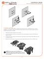
Wall Mount installation
To install the HDVS-CAM-HDMI, 4 M6 swelling bolts, 1 1/4 20UNC bolt, 4 M6 nuts & shims, the
included wall mount bracket, and the HDVS-CAM-HDMI are needed.
1 Install the M6 swelling bolts in a rectangular pattern on the wall, 100 mm wide and 50 mm
high.
2 Attached the wall mount bracket onto the wall, by placing them on the M6 swelling bolts
and securing it with the M6 nuts and shims.
3 Once the wall mount bracket is secure on the wall, place the camera on the top of the wall
mount bracket and secure it with the 1/4 20UNC bolt.

Installation Guide
AT-HDVS-CAM-HDMI-BK and AT-HDVS-CAM-HDMI-WH
3
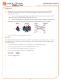
Ceiling Mount installation
To install the HDVS-CAM-HDMI, 4 PA3X30 self-tapping screws, 4 PM3X6 screws, 4 screw
stoppers, 1 1/4 20UNC screw, the optional ceiling upper and lower covering plates, and the
HDVS-CAM-HDMI are needed.
1 Install the 4 screw stoppers in the ceiling.
2 Connect the upper ceiling covering plate to the screw stoppers using the PA3X30 self-
tapping screws.
3 Connect the lower ceiling covering plate to the bottom of the HDVS-CAM-HDMI using the
1/4 20UNC screw.
4 Mount the lower ceiling covering plate to the upper ceiling plate using 3 PM3X6 bolts.
ON KE
1 2
ON KE
1 2
1
0
X
Z
o
o
m
F
1
.
6
-
F
3
.
0
f
4
.
7
m
m
-
f
4
7
m
m
1
0
X
Z
o
o
m
F
1
.
6
-
F
3
.
0
-
f
4
7
m
m
1
0
X
Z
o
o
m
F
1
.
6
-
F
3
.
0
f
4
.
7
m
m
-
f
4
7
m
m
1
0
X
Z
o
o
m
F
1
.
6
-
F
3
.
0
-
f
4
7
m
m
NOTE: The camera picture will need to be
inverted for video to be viewed correctly. View the
HDVS-CAM-HDMI manual for instructions on how
to invert video.

Installation Guide
AT-HDVS-CAM-HDMI-BK and AT-HDVS-CAM-HDMI-WH
4
WebGUI
The HDVS-CAM-HDMI includes a built-in webGUI, which allows easy management and control
of all features if not using the on-screen OSD and remote. Follow the instructions below to ac-
cess the webGUI.
1 Use an IP scanner to determine the IP address of the HDVS-CAM-HDMI.
2 Launch a web browser and enter the IP address of the unit.
3 The HDVS-CAM-HDMI Login page will be displayed.
4 Enter the following information on the Login page.
User Name: admin
Password: Atlona
5 Click the Login button.
1 *Optional* Connect the Ethernet cable to the LAN port on the back of the HDVS-CAM.
2 Connect the camera to the input of conferencing system, video conferencing codec,
extender, PC or more.
a Connect the camera’s USB port to the USB port of a conferencing system or USB
extender such as AT-OME-EX-RX, AT-OME-SR21, etc.
b Connect the HDMI port to an HDMI device such as a video conference codec or PC.
3 *Optional* Connect the Visca to RS-232 cable to the Visca port for RS-232 control.
4 Connect the DC 12V power cable to the unit.
Installation
GND
RXD
CTS
TXD
RI
DSR
DSR
RTS
DCD
NC
TXD
DSR
DTR
GND
IR OUT
GND
RXD
Visca
Visca
RS-232
RS-232
DTR
DSR
TXD
GND
RXD
GND
IR OUT
NC
DCD
RXD
TXD
DTR
GND
DSR
RTS
CTS
RI

Installation Guide
AT-HDVS-CAM-HDMI-BK and AT-HDVS-CAM-HDMI-WH
5
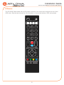
IR Remote
HOME
SET
F1 F2 F3 F4
1
AUTO
MANUAL
FOCUS ZOOM
2 3
1 2 3
4 5 6
7 8 9
*
8 #
+
_ _
+
4
CAMERA SELECT
SET
PRESET
CLEAR
PRESET
BLC
ON/OFF
MENU
The AT-HDVS-CAM comes with an IR remote control for full control of the camera and use of the
OSD menu. See the user manual for full information on the remote buttons, OSD, and presets.

Installation Guide
AT-HDVS-CAM-HDMI-BK and AT-HDVS-CAM-HDMI-WH
6
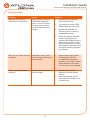
Troubleshooting
Problem Cause Solution
Why Can I not get any
picture from my camera?
Camera lens is covered,
USB/HDMI cables are
faulty, or the PC/Codec
is not set up to receive
the video feed from the
camera.
• Remove the camera lens
cover from the unit.
• Try switching out the USB/
HDMI cables for new ones.
• Bypass the extender to
verify the unit isn’t having
compatibility issues.
• Check the device manager
of the PC to ensure the
camera USB/HDMI device is
discovering correctly. If the
device is discovered, ensure
the camera is selected within
the video recording program
(e.g. Skype).
Why isn’t my video showing
correctly?
Resolution, focus, color,
and/or refresh rate may be
set incorrectly.
• Use the one of the control
interfaces (IR, RS-232,
or webGUI) to adjust the
resolution, focus the camera,
switch between 50 and 60
Hz, and many other settings.
Why is my IR remote not
working?
There is no power or too
much sunlight.
• Ensure there are fresh
batteries in the IR remote
control.
• Move the camera, so the
front panel IR window is out
of direct light.

Installation Guide
AT-HDVS-CAM-HDMI-BK and AT-HDVS-CAM-HDMI-WH
7
Notes

Installation Guide
AT-HDVS-CAM-HDMI-BK and AT-HDVS-CAM-HDMI-WH
8
Version 1
© 2020 Atlona Inc. All rights reserved. “Atlona” and the Atlona logo are registered trademarks of Atlona Inc. All other brand names and trademarks or registered
trademarks are the property of their respective owners. Pricing, specications and availability subject to change without notice. Actual products, product images,
and online product images may vary from images shown here.
Toll free US International
atlona.com • 877.536.3976 • 41.43.508.4321
-
 1
1
-
 2
2
-
 3
3
-
 4
4
-
 5
5
-
 6
6
-
 7
7
-
 8
8


Atlona AT-HDVS-CAM-HDMI-WH Installation guide
- Type
- Installation guide
- This manual is also suitable for
Ask a question and I''ll find the answer in the document
Finding information in a document is now easier with AI
Related papers
-
Atlona AT-HDVS-CAM-HDMI-WH Owner's manual
-
Atlona AT-HDVS-CAM-W Installation guide
-
-
-
-
-
Atlona AT-HDVS-CAM-CMNT Owner's manual
-
Atlona AT-OME-EX-KIT-LT User manual
-
-
Atlona AT-OME-EX-KIT Owner's manual
Other documents
-
Legrand Universal 4K HDMI Adapter Ring Owner's manual
-
Panduit ATLONA Omega AT-OME-EX-TX-WP Solutions Setup And Configuration Manual
-
Sony BRC-300 Specification
-
Sony HDR-HC3 Owner's manual
-
-
Sony HDR-HC5E User manual
-
Sony HDR-HC9E Operating instructions
-
Sony HDR-HC7 User manual
-
Samsung HDR-HC9 User manual
-