Klimaire KIWQ18H2-3T / KOIQ18H2-3 Installation guide
- Category
- Split-system air conditioners
- Type
- Installation guide
This manual is also suitable for

KIWQ/KOIQ
Mark of Superior Quality
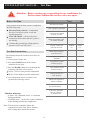
IMPORTANT NOTE:
Read this manual carefully before installing
or operating your new air conditioning
unit. Make sure to save this manual for
future reference.
For more information please visit www.klimaire.com
Installation Manual
IMIQ 20-07

CONTENTS
This document, illustration, data,information herein contains are the property
of Klimaire products inc. and can't be duplicated, modified or reproduced by any means.
INSTALLATION PLACE .................................................................................... 1
INSTALLATION.................................................................................................... 2
MAINTENANCE ..................................................................................................... 15
TROUBLESHOOTING............................................................................................. 16

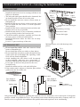
OUTDOOR UNIT
INSTALLATION MANUAL---Selecting the Installation Place
1
Install the indoor unit level on a strong wall that is not
subject to vibrations.
The inlet and outlet ports should not be obstructed: the
air should be able to blow all over the room.
Do not install the unit near a source of heat, steam, or
flammable gas.
Install the unit near an electric socket or private circuit.
Do not install the unit where it will be exposed to
direct sunlight.
Install the unit where connection between indoor and
outdoor unit is as easy as possible.
Install the unit where it is easy to drain the condensed
water, preferebly inside of an exterior wall.
Check the machine operation regularly and leave the
necessary space (as shown in the picture).
Install the indoor unit where the filter can be easily
accessible.
Leave a 6" space on the top of the unit.
condensed water drain pipe
Sleeve
insulating covering
electrical cable
Mounting plate
Do not install the outdoor unit near sources of heat,
steam or flammable gas.
Do not install the unit in too windy or dusty places.
Do not install the unit where people often pass.Select
a place where the air discharge and operating sound
level will not disturb neighbours.
Avoid installing the unit where it will be exposed
to direct sunlight ( other wise use a protection , if
necessary, that should not interfere with the air flow).
Leave space as shown in the picture for the air to
circulate freely.
Install the outdoor unit in a safe and solid place.
If the outdoor unit is subject to vibration, place rubber
gaskets onto the feet of the unit.
water drain pipe
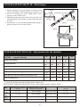
Minimum space to be left showing in the
picture
Outdoor unit
Indoor unit
be le
ss
th
a
n 16 ft
Height
s
hould
Outdoor unit
Indoor unit
b
e les
s t
ha
n 16 ft
Heigh
t shou
ld
Installation Diagram
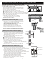
INDOOR UNIT
Only persons and/or companies qualified and experienced in the installation, service and repair of refrigerant
products should be permitted to do so. The purchaser must ensure that the person and/or company who is to
Pipe length is
install, service or repair this air conditioner has qualifications and experience in air conditioning.
50' (15m)Max
Pipe length is
50' (15m)Max
20
500mm
20
500mm
12
300mm
12
300mm
79
2000mm
6 or
150mm
6 or
150mm
6 or
150mm
Note
Quick connect
piping kit 25 ft long

INSTALLATION MANUAL---Installation of the Indoor unit
1. By using a level, put the mounting plate in a perfect
square position vertically and horizontally.
2. Drill 1 1/4 inch deep holes in the wall to fix the
plate, following the screw remark;
3. Insert the plastic anchors into the hole;
4. Fix the mounting plate by the provided screws;
5. Check that the mounting plate is correctly fixed;
Note : Keep the drain pipe down towards the direction
of the wall hole, otherwise leakage may occur.
Before starting installation, decide on the position of the
indoor and outdoor units, taking into account the minim-
um space required around the units.
Install the indoor unit in the room to be air
avoiding in corridors or communal areas. conditioned
Install the indoor unit at a height of at least 8 ft
from the ground.
To install, proceed as follows:
1. Drill the hole in the wall for the copper pipe crossing,
following the quick-installation paper board marked
suggested diameter is 2-3/4 in.
2. Set a flexible flange through the hole in the wall to
keep the latter intact and clean.
The hole must slope downwards towards the exterior.
Note : The shape of the mounting plate may be different
from the one above, but installation method is similar .
1. The cable wires are connected to the main PCB of indoor
unit by manufacturer according to the model without terminal block.
2. Lift the front panel. Take of the cover as indicated.
3. Hold the indoor plug connerctor and instert the mating plug
connector located on the indoor unit until it makes a clicking sound.
The Y/G wire should be connected individually.
Secure the cable onto the control board with the cord clamp.
4. The plug must be installed and fasten reliably.
5. An efficient earth connection must be ensured.
6. If the power cable is damaged, it must be replaced by
a certified service techincian
Front panel
Terminal block cover
wiring diagram
Installation of the mounting plate
Drilling a hole in the wall for the piping
Electrical connections---Indoor unit
2
Check the top of indoor unit carton box, there is a quick-
installation paper board, it is a guideline to find the screw
and hole drilling position quickly.
2.75 inch
Wall
Indoors
Outdoors
5-7mm
(0.2-0.3in)
1) Place the paper board on the wall where the unit will be installed.
2) Use a level to align the paper board.
3) Mark the screw holes and center of drilling
hole on the wall with a screw or screwdriver
1. Insert the round plastic wall sleeeve into the hole
2. If the sleeve sticks out cut the plastic sleeve with utility knife
to be flush with wall.
3. Insert the sleeve cap on the exterior part fo the wall
Indoors
Outdoors

3
INSTALLATION MANUAL - Indoor Unit installation
The copper pipe should be set through the wall to outside
when installing the indoor unit, for quick-connecting
product.
Run the piping in the direction of the wall hole, and put
the drain pipe at the bottom, then bind the copper pipes
and the drain pipe and the power cables together with
the tape, so that water can flow away freely.
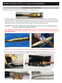
Do not remove the cap from the pipe until connecting
it, to avoid dampness or dirt from entering.
If the pipe is bent or pulled too often, it will become
stiff. Do not bend the pipe more than three times at
one point.
When extending the rolled pipe, straighten the pipe by
unwinding it gently as shown in the picture.
Unrolling the pipes
Indoor unit condensate water drainage
The indoor unit condensed water drainage is fundamen-
tal for the success of the installation.
1. Place the drain hose below the piping, taking care not
to create siphons.
2. The drain hose must slant downwards to aid drainage.
3. Do not bend the drain hose or leave it protruding or
twisted and do not put the end of it in water. If an
extension is connected to the drain hose, ensure that
it is lagged when it passes into the indoor unit.
4. If the piping is installed to the right, the pipes, power
cable and drain hose must be lagged and secured onto
the rear of the unit with a pipe connection.
A) Insert the pipe connection into the relative slot.
B) Press to join the pipe connection to the base.
YES
Refrigerant piping setting position
NO NO
NO
YES
Extending the rolled pipe
Condensed water drain pipe
(at the bottom of bundle)
Sleeve
Insulating covering
Mounting plate
6 or
150mm
6 or
150mm
6 or
150mm
Inclined donwards
1.
2.

INSTALLATION MANUAL - Indoor Unit installation
4
1. Remove the indoor unit pipe cap (check that there is no debris inside).
Connections to the indoor unit
Smoothly align the female quick connector to the male one which is fixed with indoor unit by hand at first,
and fasten smoothly. Hold the short position (picture A) of male quick connector by open-end spanner and do
not turn, use torque wrench to take the short position (picture B) of the female quick connector which fixed
with long copper pipe, and quickly turn to tight en them. Follow the proper torque chart.
Picture A Picture B
3. In order to protect the quick-connector, and prevent condensation on the union, please cover the
quick-connector with the deadening pads, when finish fastening the copper pipe to the quick-connector.
4. Use the insulation to cover the quick-connector, and use the tape to fasten them tightly together.
Be sure to put the drain pipe at the bottom, after start up, test run and performed gas leak test.
IMPORTANT: Since the coupling works with trapping rings, it may leak if you undo and reconect
the pipes. This will also void the warranty.
After completing the connection, check all the connections are sealed correctly using leak detection spray or
soap suds. If any bubbles form, the system has a leak on the screw connector must be re-tightened using an
open-ended spanner.
2.
After you start and test run the system make sure there are no gas leaks, then proceed to item 3

Covered by vinyl tape
mounting plate
refrigerant
pipe
refrigerant
pipe
insulation
sleeve
connection
cable
Condensed water
drain pipe
INSTALLATION MANUAL - Indoor Unit installation
INSTALLATION OF THE INDOOR UNIT
After having connected the pipe according to the instruc-
tions, install the connection cable plugs firmly.
Now install the plastic drain extension pipe.
After connection, wrap the pipes, cable and drain pipe
with the insulating tape.
1. Arrange the pipes, cables and drain hose well.
2.Wrap the pipe joints with insulating material, securing
it with vinyl tape.
3. Run the bound pipe , Cables and drain pipe through
the wall hole and mount the indoor unit onto the upper
part of the mounting plate securely.
4. Press and push the lower part of the indoor
unit tightly against the mounting plate.
INSTALLATION MANUAL - Outdoor Unit installation
The outdoor unit should be installed on a solid wall
and fastened securely or in some some cases on a leveled slab
The following procedure must be observed before co-
nnecting the pipes and connecting cables: decide
which is the best position on the wall and leave enough
space to be able to carry out maintenance easily.
Fasten the support to the wall using screw anchors
which are particularly suited to the type of wall.
Use a larger quantity of screw anchors than normally
required for the weight they have to bear to aviod
vibration during operation and remain fastened in the
same position for years without the screws becoming
loose.
The unit must be installed following national
regulations.
5
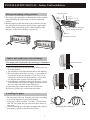
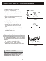
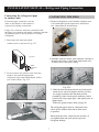
Installation of Drain Joint
Heat pump units require a drain joint. Before
bolting the outdoor unit in place, you must install
the drain joint at the bottom of the unit. Note
that there are two different types of drain joints
depending on the type of outdoor unit.
Base pan hole of
outdoor unit
Fig. 23.4
Fig. 23.
Fig. 23.2
Fig. 23.3

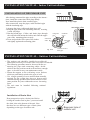
INSTALLATION MANUAL - Outdoor Unit installation
If the drain joint comes with a rubber seal
(see Fig. 24.1), do the following:
1. Fit the rubber seal on the end of the drain joint
that will connect to the outdoor unit.
2. Insert the drain joint into the hole in the base
pan of the unit.
o
3. Rotate the drain joint 90 until it clicks in place
facing the front of the unit.
4. Connect a drain hose extension (not included)
to the drain joint to redirect water from the
unit during heating mode.
If the drain joint doesn t come with a rubber
seal (see Fig. 24.2), do the following:
1. Insert the drain joint into the hole in the base
pan of the unit. The drain joint will click in
place.
2. Connect a drain hose extension (not included)
to the drain joint to redirect water from the
unit during heating mode.
Seal
Drain joint
Fig. 24.1
Seal
IN COLD CLIMATES
is as vertical as possible to ensure swift water
drainage. If water drains too slowly, it can
freeze in the hose and flood the unit.
,
In cold climates, make sure that the drain hose
6
Fig. 24.2
drain pipe
The condensed water and the ice formed in the outdoor
unit during heating operation can be drained through the
drain pipe.
1. Fasten the drain port in the 1 inch hole placed in the
part of the unit as shown in the picture.
2. Connect the drain port and the drain pipe.
that water is drained in a suitable place.Make sure
Outdoor unit condensate water drainage
(only for heat pump models)
drain port
Fig. 24.3

Fig.25.1
Fig.25.2
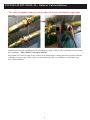
Ensure the pipe connectors are the
same to the indoor´s and outdoor´s
respectively during connection.
Connecting the refrigerant pipe
to outdoor unit
1. First remove the water tray on the
outdoor unit as shown in Fig.25.1.
2. Do not remove the plastic seals from the
outdoor unit and the appropriate
refrigerant pipes until immediately before
you connect them, Fig.25.2
Refrigerant Piping Connection
Large size connector must be connected with
the large size outdoor unit quick connector that has
an aditional port to check pressure or charge
refrigerant
CONNECTING THE PIPES
3. Remove the plastic seals from the outdoor unit
valve and male quick connectors until when
you immediately install them.
4. Smoothly align the female quick connector correctly to
the male one which is fixed with outdoor unit valve
by hand at first, and fasten simply.
5. Hold the short position (remark A) of male quick
connector by open-end spanner and do not turn,
use torque wrench to take the short position
(remark B) of the female quick connector which
is fixed with long copper pipe, and quickly turn to
tighten them.
Follow the proper torque chart on page 26.
The refrigerant pipes must be connected to the
valves on the outdoor unit with as little stress
as possible.
Ensure that the screw connectors do not skew as
you tighten them and work quick to prevent
refrigerant leakage.
Fig.25.3
7
Water
protective
tray
INSTALLATION MANUAL---

INSTALLATION MANUAL - Outdoor Unit installation
8
Important! The conical ring on the valve has an imoportant sealing function together with the
sealing seat in the caps. Ensure that you do not damage the cone and that you keep the cap
free of dirt and dust.
Two open end spanners must be used in order not to twist and kink the copper pipe.
Important! Since the couplings work with tapping rings, it may leak if you undo and reconnect
the couplings. This will also void the warranty

INSTALLATION MANUAL - Outdoor Unit installation
9
Proper torque chart
Coupling dimension
Pound-force(1bf-ft)
Newton meter(N-m)
Kg-force meter(kgf-m)
( 6.35)9.5mm dash size
( 9.52)12.7mm dash size
( 12.7)19mm dash size
( 16)25.4mm dash size
11.8
11.8
13.3
14.8
16
16
18
20
1.7
1.7
1.9
2.1
Note: Leakage check. After completing the installation, check all the connecting are sealed
correctly using leak detection spray or soap suds. If any bubbles form, the system has a leak
and the screw connerctors must be re-tightened usingan open-ended spanner.
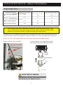
3. Remove the cover of outdoor valves both 2-way vale (liquid valve) and 3-way vale (suction valve), use
the inner-hexagon (allen wrench) spanner to open the outdoor valve core, by turning it counter-clockwise.
If the valve core is not opened fully, the system may malfunction or suffer damage.
Then re-screw the valve cover back.
4. Connecting the wire by plugging the quick
connecting cable for both indoor and outdoor.
NOTE ABOUT WIRING
THE WIRING CONNECTION PROCESS MAY
DIFFER SLIGHTLY AMONG UNITS
Conne
ctor
P
ower
su
pply
Y/G
L N1
3
2
Fig.26.1
Fig.26.2
Fig.26.3

Electrical Safety Checks
is installed in accordance with local and national
regulations, and according to the Installation
Manual.
BEFORE TEST RUN
Check Grounding Work
Measure grounding resistance by visual detection
and with grounding resistance tester. Grounding
Note: This may not be required for some
locations in the US.
DURING TEST RUN
Check for Electrical Leakage
During the Test Run, use an electroprobe and
multimeter to perform a comprehensive electrical
leakage test.
If electrical leakage is detected, turn off the unit
immediately and call a licensed electrician to find
and resolve the cause of the leakage.
Note: This may not be required for some
locations in the US.
WARNING - RISK OF
ELECTRIC SHOCK
ALL WIRING MUST COMPLY WITH LOCAL
AND NATIONAL ELECTRICAL CODES,
AND MUST BE INSTALLED BY A LICENSED
ELECTRICIAN.
Gas Leak Checks
There are two different methods to check for gas
leaks.
Soap and Water Method
Using a soft brush, apply soapy water or liquid
detergent to all pipe connection points on the
indoor unit and outdoor unit. The presence of
bubbles indicates a leak.
Leak Detector Method
If using leak detector, refer to the device s
operation manual for proper usage instructions.
AFTER PERFORMING GAS LEAK CHECKS
After confirming that the all pipe connection
points DO NOT leak, replace the valve cover
on the outside unit.
After installation, confirm that all electrical wiring
,
10
Electrical and Gas Leak Checks
DOUBLE-CHECK PIPE CONNECTIONS
During operation, the pressure of the
refrigerant circuit will increase. This may
reveal leaks that were not present during your
initial leak check. Take time during the Test
Run to double-check that all refrigerant pipe
connection points do not have leaks. Refer to
Gas Leak Check section for instructions.
After the Test Run is successfully complete, and you
confirm that all checks points in List of Checks to Perform
have PASSED, do the following:
a. Using remote control, return unit to
normal operating temperature.
b. Using insulation tape, wrap the indoor
refrigerant pipe connections that you
left uncovered during the indoor unit
installation process.
INSTALLATION MANUAL -

Before Test Run
Only perform test run after you have completed
the following steps:
Electrical Safety Checks - Confirm that
the unit s electrical system is safe and
operating properly.
Gas Leak Checks - Check all fare nut
connections and confirm that the system is
not leaking.
Confirm that gas and liquid (high and low
pressure) valves are fully open.
Test Run Instructions
minutes.
1. Connect power to the unit.
2. Press the ON/OFF button on the remote
controller to turn it on.
3. Press the MODE button to scroll through the
following functions, one at a time:
COOL - Select lowest possible temperature
HEAT - Select highest possible temperature
4. Let each function run for 5 minutes, and
perform the following checks:
List of Checks to Perform PASS/FAIL
No electrical leakage
Unit is properly grounded
All electrical terminals
properly covered
Indoor and outdoor units
are solidly installed
All pipe connection
points do not leak
Outdoor
(2):
Indoor
(2):
Water drains properly
from drain hose
All piping is properly
insulated
Unit performs COOL
function properly
Unit performs HEAT
function properly
Indoor unit louvers
rotate properly
Indoor unit responds to
remote controller
,
You should perform the Test Run for at least 30
Test Run
Set point functions
Is there any abnormal
noise or vibration
on outdoor unit
11
Is there any abnormal noise or vibration
during operation?
Could the noise , the air flow or the condensed
water drainage disturb the neighbours?
Outdoor unit test
Note: The electronic controller allows the
compressor to start only three minutes
after voltage has reached the system.
INSTALLATION MANUAL -
Attention:
Before starting up or operating the air conditioner for
the first time, confirm the service valves are open.

12
INSTALLATION MANUAL - Final stages
wall
(indoor) (outdoor)
piping
piping
gasket
insulating tape
insulating covering
Clamps
1. Wind insulating covering around the connectors of the
indoor unit and fix it with insulating tape. (page 22 (3,4)
2. Fix the exceeding part of the signal cable to the
piping or to the outdoor unit.
3. Attach the piping to the wall ( after having coated it with
insulating tape) using clamps or insert them into pla-
stic slots.
4. Seal the hole in the wall through which the piping is
passed so that no air or water can fill.
INSTALLATION MANUAL - Information for the installer
(1) Refer to the data rating label sticked on the outdoor unit.
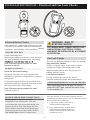
TIGHTENING TORQUE FOR PROTECTION CAPS AND FLANGE CONNECTION
PIPE
1/4
( 6)
3/8
( 9.52)
1/2
( 12)
5/8
( 15.88)
TIGHTENING TORQUE
[lb x ft]
TIGHTENING TORQUE
[lb x ft]
CORRESPONDING STRESS
(using a 0.7 ft wrench)
11 - 15
23 - 26
26 - 33
55 - 59
Service port nut
Protection caps
5 - 6.5
18 - 22
wrist strength
arm strength
arm strength
arm strength
MODEL capacity (Btu/h)
9K
12K
18K
24K
Liquid pipe diameter
Gas pipe diameter
Lenght of pipe with standard charge
Maximum distance between indoor and outdoor unit
Max. diff. in level between indoor and outdoor unit
Type of refrigerant(1)
1/4
( 6)
3/8
( 9.52)
3/8
( 9.52)
3/8
( 9.52)
1/2
( 12.7)
24.5ft
24.5ft
24.5ft
24.5ft
49ft 49ft 49ft 49ft
6g/ft 6g/ft 6g/ft 6g/ft
16ft
16ft 16ft 16ft
INVERTER TYPE
Additional refrigerant charge
R410A R410A R410A R410A
36K
3/8
( 9.52)
5/8
( 15.88)
24.5ft
49ft
9g/ft
16ft
R410A
1/4
(6)
1/4
(6)
1/4
(6)

13
INSTALLATION MANUAL - Information for the installer
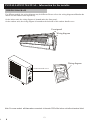
WIRING DIAGRAM
Note: For some models connected to the main PCB of the indoor unit without terminal
block.
will have wires
For different models, the wiring diagram may be different. Please refer to the wiring diagrams
indoor unit and outdoor unit respectively.
On the indoor unit, the wiring diagram is l under the front panel;
On the outdoor unit, the wiring diagram is l on the backside of the outdoor handle cover.
affixed to the
ocated
ocated
Front panel
Wiring diagram
Wiring diagram
Outdoor handle cover

14
INSTALLATION MANUAL - Information for the installer
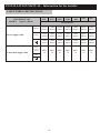
CABLE WIRES SPECIFICATION
18K
24K
Power supply cable
Connection supply cable
3(L)
2(N)
1(S)
N(L2)
L(L1)
sectional area
INVERTER TYPE
MODEL capacity (Btu/h)
9K-
115V
12K-
115V
AWG
16
9K-
230V
12K-
230V
36K
AWG
16
AWG
16
AWG
16
AWG
16
AWG
16
AWG
16
2
3.0mm
2
3.0mm
2
3.0mm
AWG12
AWG12
2
3.0mm
2
3.0mm
2
3.0mm
AWG12
AWG12
AWG12AWG12
2
3.0mm
2
3.0mm
2
3.0mm
AWG12
AWG12
AWG12
2
3.0mm
2
3.0mm
2
3.0mm
AWG12
AWG12
AWG12
2
3.0mm
2
3.0mm
2
3.0mm
AWG12
AWG12
AWG12
2
3.0mm
2
3.0mm
2
3.0mm
AWG12
AWG12
AWG12
2
3.0mm
2
3.0mm
2
3.0mm
AWG12
AWG12
AWG12

15
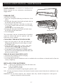
MAINTENANCE
Periodic maintenance is essential for keeping your air
conditioner efficient.
Before carrying out any maintenance, t
off .
urn the power
supply
INDOOR UNIT
ANTIDUST FILTERS
1. Open the front panel (following the direction of the
arrow).
2. Keeping the front panel raised with one hand, take out
the air filter with the other hand.
3. Clean the filter with water; if the filter is soiled with
oil, it can be washed with warm water, not exceeding
113 (45 ).
Leave to dry in a cool and dry place.
4. Keeping the front panel raised with one hand, insert
the air filter with the other hand.
5. Close f .ront panel
The electrostatic and the deodorant filter (if installed)
cannot be washed and must be replaced with new
filters once every 6 months.
CLEANING THE HEAT EXCHANGER
1. Open the front panel of the unit and
unhooking it from the hinges to make
the cleaning easier.
2. Clean the indoor unit using a cloth with water
not higher than 104 (40 ) and neutral soap.
Never use aggressive solvents or detergents.
3.
remove by
lifting up and
If the battery of the outdoor unit is clogged, remove
any leaves or waste by hand and remove the dust with
an air jet or a bit of water.
END OF SEASON MAINTENANCE
1. Disconnect the automatic switch or the plug.
2. Clean and replace the filters.
3. On a sunny day let the air conditioner work on ventilation for several hours, so that the inside of the unit
can dry completely.
REPLACING THE BATTERIES
When:
How:
N.B: Use only new batteries. Remove the batteries from the remote control when the air conditioner is not
in operation.
WARNING ! Do not throw batteries into common trash, they should be disposed of in the special
containers situated in collection points.
Anti-dust filter
There is no confirmation beep from the indoor unit.
The LCD activate.doesn't
.Remove back cover plate
Place the new batteries respecting the symbols + and - .
INSTALLATION MANUAL -

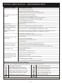
TROUBLESHOOTING
MALFUNCTION
Strange odor
The appliance does not
operate
Noise of running water
A fine mist comes from
the air outlet
Insufficient airflow, either
hot or cold
The appliance does not
respond to commands
The display is off
Switch off the air condi-
tioner immediately and
cut off the power supply
in the event of:
ERROR SIGNALS ON THE DISPLAY
POSSIBLE CAUSES
Power failure/plug pulled out.
Damaged indoor/outdoor unit fan motor.
Faulty compressor thermomagnetic circuit breaker.
Faulty protective device or fuses.
Loose connections or plug pulled out.
It sometimes stops operating to protect the appliance.
Voltage higher or lower than the voltage range.
Active TIMER-ON function.
Damaged electronic control board.
Dirty air filter.
Back flow of liquid in the refrigerant circulation.
This occurs when the air in the room becomes very cold, for example in the
COOLING or DEHUMIDIFYING/DRY modes.
This noise is made by the expansion or contraction of the front panel due
to variations in temperature and does not indicate a problem.
Unsuitable temperature setting.
Obstructed air conditioner intakes and outlets.
Dirty air filter.
Fan speed set at minimum.
Other sources of heat in the room.
No refrigerant.
Remote control is not close enough to indoor unit.
The batteries of remote control need to be replaced.
Obstacles between remote control and signal receiver in indoor unit.
Active LIGHT function.
Power failure.
Strange noises during operation.
Faulty electronic control board.
Faulty fuses or switches.
Spraying water or objects inside the appliance.
Overheated cables or plugs.
Very strong smells coming from the appliance.
A strange noise can be
heard
Indoor temperature sensor fault
Description of the troubleDisplay
Outdoor pipe temperature sensor fault
Indoor pipe temperature sensor fault
Malfunction of indoor fan motor
Refrigerant system leakage or fault
Outdoor air temperature sensor fault
Outdoor discharge temperature sensor fault
Outdoor IPM module fault
Description of the trouble
Display
Outdoor PCB EEPROM fault
Outdoor current detect fault
In case of error, the display on the indoor unit shown the following error codes:
Outdoor suction temperature sensor fault
Outdoor fan motor fault
INSTALLATION MANUAL -
16

The design and specifications are subject to change without prior notice for
product improvement. Consult with the sales agency or manufacturer for details.
The Klimaire logo is a registered Trademark of Klimaire Products Inc.
Copyright 2020 Klimaire Products Inc.
Tel: (305) 593 - 8358
www.klimaire.com
2190 NW 89 Place, Doral, FL 33172 - USA
TM
Do the ON/OFF and FAN operate normally?
Does the MODE operate normally?
Do the set point and TIMER function properly?
Does each lamp light normally?
Do the flap for air flow direction operate normally?
Is the condensed water drained regularly?
Indoor unit test
Mark of Superior Quality
IMIQ 20-07
-
 1
1
-
 2
2
-
 3
3
-
 4
4
-
 5
5
-
 6
6
-
 7
7
-
 8
8
-
 9
9
-
 10
10
-
 11
11
-
 12
12
-
 13
13
-
 14
14
-
 15
15
-
 16
16
-
 17
17
-
 18
18
-
 19
19


Klimaire KIWQ18H2-3T / KOIQ18H2-3 Installation guide
- Category
- Split-system air conditioners
- Type
- Installation guide
- This manual is also suitable for
Ask a question and I''ll find the answer in the document
Finding information in a document is now easier with AI
Related papers
-
Klimaire KIWQ18H2-3T / KOIQ18H2-3 Installation guide
-
Klimaire KTHM-BC User manual
-
-
Klimaire KSID032-H215 Warranty
-
-
-
-
-
-
Klimaire KSIH012-H222 -O/-I Installation guide
Other documents
-
Haier HW-05LMA13 User manual
-
Danby DAS180EAQHWDB Owner's manual
-
 Order Home Collection 3328057 Operating instructions
-
GREE Free Match Cozy GWH Ind Installation guide
-
Bosch 8733954443 Installation guide
-
White-Westinghouse WASE12C2ABLW User manual
-
LG AMNQ18GSKB0 Installation guide
-
McQuay MCM020D User manual
-
Fujitsu ASMG30CMTA Installation guide
-
Sanyo KS3082 Installation Instructions Manual
