Bosch 8733954443 Installation guide

Category
Split-system air conditioners
Type
Installation guide
Bosch Multi Zone Ductless Air Conditioner / Heat Pump
Climate 5000 Series
Installation Manual
2
|
Bosch Climate 5000 Series Multi Zone Ductless Air Conditioner / Heat Pump Installation Manual
05.2019 | Bosch Thermotechnology Corp.
Data subject to change
Installation Manual Bosch Climate 5000 Series Multi Zone Ductless Air Conditioner / Heat Pump | 3
Bosch Thermotechnology Corp. | 05.2019
Data subject to change
Table of Contents
1 Key to Symbols and Safety Instructions 4
1.1 Key to Symbols 4
1.2 Safety 4
2 Components 6
3 Installation Summary 7
4 Installation Diagram 8
5 Speci cations 9
6 Outdoor unit installation 10
7 Refrigerant Piping Connection 14
7.1 Connection Instructions – Refrigerant Piping 14
8 Wiring 17
8.1 Outdoor unit wiring 17
8.2 Wiring Diagrams 18
9 Air Evacuation 21
9.1 Preparations and Precautions 21
9.2 Evacuation Instructions 21
9.3 Adding Refrigerant 22
10 Electrical and Gas Leak Checks 23
10.1 Electrical Safety Checks 23
10.2 Gas Leak Checks 23
11 Test Run 24
11.1 Before Test Run 24
11.2 Test Run Instructions 24
12 Automatic Wiring/Piping Correction Function 25
12.1 How To Activate This Function 25
13 Features and Operation 26
13.1 Protection of the Air Conditioner 26
13.2 Operation 26
14 Troubleshooting 27
14.1 Common Issues 27
14.2 Error Codes 28
15 Disposal Guidelines 29
4
|
Bosch Climate 5000 Series Multi Zone Ductless Air Conditioner / Heat Pump Installation Manual
05.2019 | Bosch Thermotechnology Corp.
Data subject to change
1 Key to Symbols and Safety Instructions
1.1 Key to Symbols
Warnings
Warnings in this document are identifi ed by a
warning triangle printed against a grey background.
Keywords at the start of a warning indicate the type and seriousness
of the ensuing risk if measures to prevent the risk are not taken.
The following keywords are defi ned and can be used in this document:
DANGER indicates a hazardous situation which, if not avoided, will result
in death or serious injury.
WARNING indicates a hazardous situation which, if not avoided, could
result in death or serious injury.
CAUTION indicates a hazardous situation which, if not avoided, could
result in minor to moderate injury.
NOTICE is used to address practices not related to personal injury.
Important information
 This symbol indicates important information where
there is no risk to people or property.
1.2 Safety
Please read safety precautions before installation
Incorrect installation due to ignoring instructions can cause serious damage or
injury.
WARNING:
In certain functional environments, such as kitchens, server
rooms, etc., the use of specially designed air-conditioning
units is highly recommended.
WARNING: ELECTRICAL HAZARD
Do not modify the length of the power supply cord or use an
extension cord to power the unit.
Do not share the electrical outlet with other appliances.
Improper or insufficient power supply can cause fire or
electrical shock.
WARNING: INSTALLATION REQUIREMENTS
Installation must be performed by a licensed contractor,
and per the instructions in the installation manual. Improper
installation can cause water leakage, electrical shock, or fire.
In North America, installation must be performed in
accordance with the requirement of NEC (National Electric
Code) and CEC (Canadian Electric Code) by licensed and
qualified personnel only.
Only contact a licensed contractor for repair or maintenance
of this unit.
Only use the included accessories, parts, and specified
parts for installation. Using non-standard parts can cause
water leakage, electrical shock, fire, and can cause the unit
to fail.
Install the unit in a solid location that can support the unit’s
weight. If the chosen location cannot support the unit’s
weight, or the installation is not done properly, the unit may
drop and cause serious injury and/or damage.
Before you install the unit, consider strong winds, typhoons
and earthquakes that might affect your unit and locate it
accordingly. Failure to do so could cause the equipment to
fail.
After installation, ensure there are no refrigerant leaks and
that the unit is operating properly. Refrigerant is both toxic
and flammable and poses a serious health and safety risk.
Installation Manual Bosch Climate 5000 Series Multi Zone Ductless Air Conditioner / Heat Pump | 5
Bosch Thermotechnology Corp. | 05.2019
Data subject to change
WARNING:
This product can expose you to chemicals including Lead
and Lead components, which are known to the State
of California to cause cancer and birth defects or other
reproductive harm. For more information go to
www.
P65Warnings.ca.gov
.
WARNING: ELECTRICAL HAZARD
For all electrical work, follow all local and national wiring
standards, regulations, and the Installation Manual.
The power supply to the outdoor unit requires a service
disconnect at the unit. Only use a dedicated circuit. Never
share a power source connected to this system. Insufficient
electrical capacity or defects in electrical work can cause
electrical shock or fire.
For all electrical work, use the specified cables. Connect
cables tightly, and clamp them securely to prevent external
forces from damaging the terminal. Improper electrical
connections can overheat and cause fire, and may also
cause shock.
All wiring must be properly arranged to ensure that the
control board cover can close properly. If the control board
cover is not closed properly, it can lead to corrosion and
cause the connection points on the terminal to heat up,
catch fire, or cause electrical shock.
If the power supply cord is damaged, it must be replaced
by the manufacturer, its service agent or similarly qualified
persons such as a licensed electrician in order to avoid a
hazard.
The product must be properly grounded at the time of
installation, or electrical shock may occur.
CAUTION: BURN HAZARD
For units that have an auxiliary electric heater, do not
install the unit within 1 meter (3 feet) of any combustible
materials.
Do not install the unit in a location that may be exposed
to combustible gas leaks. If combustible gas accumulates
around the unit, it may cause fire.
Do not operate your air conditioner in a wet room such as a
bathroom or laundry room. Too much exposure to water can
cause electrical components to short circuit.
NOTICE: PROPERTY DAMAGE
Install condensate drainage piping according to the
instructions in this manual. Improper condensate drainage
may cause water damage to your home and property.
CAUTION: CONTAINS REFRIGERANT
This air-conditioning unit contains fluorinated gases. For
specific information on the type of gas and the amount,
please refer to the relevant label on the outdoor unit itself.
Installation, service, maintenance and repair of this unit
must be performed by a certified technician.
Product removal and recycling must be performed by a
certified technician.
If the system has a leak-detection system installed, it must
be checked for leaks at least every 12 months.
When the unit is checked for leaks, proper record-keeping of
all checks is strongly recommended.
6
|
Bosch Climate 5000 Series Multi Zone Ductless Air Conditioner / Heat Pump Installation Manual
05.2019 | Bosch Thermotechnology Corp.
Data subject to change
2 Components
The air conditioning / heat pump system installation requires the following
components. Use all of the installation parts and components to install the air
conditioner. Improper installation may result in water leakage, electrical shock and
re, or equipment failure.
Name Quanity
Drain joint 1
Seal ring 1
Connecting pipe assembly
Liquid side
Φ6.35 (1/4 in)
Parts not included.
Piping kits are available
as an accessory.
Φ9.52 (3/8 in)
Gas side
Φ9.52 (3/8 in)
Φ12.7 (1/2 in)
Φ 16 (5/8 in)
Multi-zone installation manual 1
Transfer connector
NOTE: Pipe sizes may vary between air handler and condensing section connections. To meet diff erent pipe size requirements,
it may be necessary to install an adapter (transfer connector) on the outdoor unit connection.
Not included, but may be
required - 1 per indoor unit
Magnetic ring (Hitch on the connective cable between the indoor unit and outdoor unit after installation.)
Not included, but
recommended to use
1 per cable.
Power cable for connection with external power supply
Not included (see section 9
for cable requirements)
Table 1
Installation Manual Bosch Climate 5000 Series Multi Zone Ductless Air Conditioner / Heat Pump | 7
Bosch Thermotechnology Corp. | 05.2019
Data subject to change
3 Installation Summary
Figure 1
LN
1
2
3
MC MC
4
5
Install the outdoor unit
(Page 10)
Evacuate the refrigeration
system
(Page 21)
Connect the wires
(Page 17)
Connect the refrigerant pipes
(Page 14)
Perform a test run
(Page 23)
8
|
Bosch Climate 5000 Series Multi Zone Ductless Air Conditioner / Heat Pump Installation Manual
05.2019 | Bosch Thermotechnology Corp.
Data subject to change
4 Installation Diagram
Figure 2
More than 5.9in
More
than 78.7in
1
5
3
2
4
6
Two-Zone
Three-Zone
Four-Zone
Five-Zone
More than
4.7in
More than
4
.7in
Air Filter
Air Filter
More than
4.7in
Air Filter
More than 4.7in
More than 23.6in
More than
11.8in
More than
11
.8in
More than
23.6in
Loop a
connective
cable
More than
4.7in
Air Filter
Number Name
1 Installation plate
2 Mounting screw
3 Clip anchor
4 Signal/Power cable & Drain pipe
5 Remote control
6 Remote control holder
Table 2
  Diagram shown using Wall Mounted Indoor unit only. Indoor unit can be
changed with Four-Way Cassette, Concealed Ducted type indoors or
mixed based on applications. Please refer to Installation Manual from
Indoor Unit for Indoor unit installation procedures.
NOTICE:
Copper lines must be independently insulated.
To prevent wall damage, use a stud finder to locate studs.
A minimum pipe run of 10 ft is recommended to minimize
vibration & excessive noise.
Two of the A, B, and C air circulation pathways must be free
from obstructions at all times.
Installation Manual Bosch Climate 5000 Series Multi Zone Ductless Air Conditioner / Heat Pump | 9
Bosch Thermotechnology Corp. | 05.2019
Data subject to change
5 Speci cations
Number of units that can be used together Connected units 2-5 units
Compressor stop/start frequency Stop time 3 min or more
Power source voltage
Voltage fl uctuation within ±10% of rated voltage
Voltage drop during start within ±15% of rated voltage
Interval unbalance within ±3% of rated voltage
Table 3
2 Zone System 3 Zone System 4 Zone System 5 Zone System
Model
BMS500-AAM018-1CSXRA
BMS500-AAM018-1CSXHB
BMS500-AAM027-1CSXRA
BMS500-AAM027-1CSXHB
BMS500-AAM036-1CSXRA
BMS500-AAM036-1CSXHB
BMS500-AAM048-1CSXRA
Max. equivalent length for all indoor units 131ft / 40m 197ft / 60m 262ft / 80m 262ft / 80m
Max. length to farthest indoor unit 82ft / 25m 98ft / 30m 115ft / 35m 115ft / 35m
Max. height diff erence between indoor and
outdoor unit
49ft / 15m 49ft / 15m 49ft / 15m 49ft / 15m
Max. height diff erence between indoor units 33ft / 10m 33ft / 10m 33ft / 10m 33ft / 10m
Refrigerant precharge (total pipe length) 49ft / 15m 74ft / 23m 98ft / 30m 123ft / 37m
Additional refrigerant charge
Liquid side: 1/4in - 0.16oz/ft Liquid side: 1/4in - 0.16oz/ft
Liquid side: 1/4in - 0.16oz/ft
Liquid side: 3/8in - 0.32oz/ft
Liquid side: 1/4in - 0.16oz/ft
Liquid side: 3/8in - 0.32oz/ft
Table 4 Refrigerant pipe requirements
When installing multiple indoor units with a single outdoor unit, ensure that the
length of the refrigerant pipe and the drop height between the indoor and outdoor
units meet the requirements illustrated in the following diagram (indoor units
may be located above or below the outdoor unit as long as they meet these height
diff erence requirements):
Figure 3
33 ft (10 m)
or less
Indoor unit
Indoor unit
Outdoor unit
49 ft (15m)
or less
Max.Height difference
10
|
Bosch Climate 5000 Series Multi Zone Ductless Air Conditioner / Heat Pump Installation Manual
05.2019 | Bosch Thermotechnology Corp.
Data subject to change
6 Outdoor unit installation
Step 1: Select installation location
The outdoor unit should be installed in the location that meets the following
requirements:
Place the outdoor unit as close to the indoor unit as possible.
Ensure that there is enough room for installation and maintenance.
The air inlet and outlet must not be obstructed or exposed to strong wind.
Ensure the location of the unit will not be subject to snowdrifts,
accumulation of leaves or other seasonal debris. If possible, provide an
awning for the unit. Ensure the awning does not obstruct airflow.
The installation area must be dry and well ventilated.
There must be enough room to install the connecting pipes and cables and
to access them for maintenance.
The area must be free of combustible gases and chemicals.
The pipe length between the outdoor and indoor unit may not exceed the
maximum allowable pipe length.
If possible, DO NOT install the unit where it is exposed to direct sunlight.
If possible, make sure the unit is located far away from your neighbors’
property so that the noise from the unit will not disturb them.
If the location is exposed to strong winds (for example: near a seaside),
the unit must be placed against the wall to shelter it from the wind. If
necessary, use an awning. (See Fig.4 & 5)
Figure 4
Strong wind
Strong wind
Figure 5
Strong wind
Install the indoor and outdoor units, cables and wires at least 3 ft from
televisions or radios to prevent static or image distortion. Depending
on the radio waves, a 3 ft distance may not be enough to eliminate all
interference.
Step 2: Install outdoor unit.
NOTICE:
Be sure to remove any obstacles that may block air
circulation.
Make sure to meet minimum spatial requirement (Figure
8 & 9) to ensure there is enough room for installation and
maintenance.
Fix the outdoor unit with anchor bolts (M10).
Figure 6
23.6 in (60 cm) or more
Fix with bolts
Installation Manual Bosch Climate 5000 Series Multi Zone Ductless Air Conditioner / Heat Pump | 11
Bosch Thermotechnology Corp. | 05.2019
Data subject to change
Split type outdoor unit mounting dimensions
Outdoor Model
Outdoor Unit
Dimensions mm (in.)
W x H x D
Mounting Dimensions
mm (in.)
Distance A Distance B
BMS500-AAM018-1CSXRA
845x702x363
(33.27x27.6x14.3)
540
(21.26)
350
(13.8)
BMS500-AAM027-1CSXRA,
BMS500-AAM027-1CSXHB,
BMS500-AAM036-1CSXRA,
BMS500-AAM036-1CSXHB
946x810x410
(37.24x31.9x16.14)
673
(26.5)
403
(15.87)
BMS500-AAM036-1CSXHB,
BMS500-AAM048-1CSXRA
952x1333x415
(37.5x52.5x16.34)
634
(24.96)
404
(15.9)
Table 5
Figure 7
Split Type Outdoor Unit
H
W
W
H
A
B
D
Series installation
The relations between H, A and L are as follows:
LA
L ≤ H
L ≤ 1/2H
9.8in / 25 cm or more
1/2H < L ≤ H 11.8in / 30 cm or more
L > H Can not be installed
Table 6
Figure 8
L
H
A
59in /
150 cm
or more
9.8in /
25cm
or more
9.8in /
25cm
or more
23.6in /
60 cm
or more
118in / 300cm or more
The minimum distance between the outdoor unit and walls described
in the installation guide does not apply to airtight rooms. Be sure to keep
the unit unobstructed in at least two of the three directions (M, N, P)
(See Fig. 9)
Figure 9
M
N
P
11.8 in / 30 cm
from back wall
23.6 in / 60 cm
on right
11.8 in / 30 cm
on left
78 in / 200 cm
in front
23.6 in / 60 cm above
12
|
Bosch Climate 5000 Series Multi Zone Ductless Air Conditioner / Heat Pump Installation Manual
05.2019 | Bosch Thermotechnology Corp.
Data subject to change
Drain joint installation
Heat pump units require a drain joint. Before bolting the outdoor unit in place,
you must install the drain joint at the bottom of the unit. Note that there are two
diff erent types of drain joints depending on the type of outdoor unit.
If the drain joint comes with a rubber seal (see Figure 10, pos. A ), do the following:
1. Fit the rubber seal on the end of the drain joint that will connect to the
outdoor unit.
2. Insert the drain joint into the hole in the base pan of the unit.
3. Rotate the drain joint 90° until it clicks in place facing the front of the unit.
4. Connect a drain hose extension (not included) to the drain joint to redirect
water from the unit during heating mode.
If the drain joint doesn’t come with a rubber seal (see Figure 10, pos. B), do the
following:
1. Insert the drain joint into the hole in the base pan of the unit. The drain joint
will click in place.
2. Connect a drain hose extension (not included) to the drain joint to redirect
water from the unit during heating mode.
NOTICE
In cold climates, make sure that the drain hose is as vertical
as possible to ensure swift water drainage. If water drains
too slowly, it can freeze in the hose and flood the unit.
CAUTION: SLIPPING HAZARD
Make sure the water drains to a safe location where it will not
cause water damage or a slipping hazard.
Figure 10
Seal
Drain joint
(A) (B)
Base pan hole of
outdoor unit
Seal
Drilling a hole in the wall
You must drill a hole in the wall for the refrigerant piping, and signal cable that will
connect the indoor and outdoor units.
1. Determine the location of the wall hole based on the location of the outdoor
unit.
2. Using a 6.5 cm (2.5 in) drill bit, drill a hole in the wall.
When drilling the wall hole, make sure to avoid wires, plumbing, and
other sensitive components.
3. Place the protective wall cuff in the hole. This protects the edges of the hole
and helps seal it when you fi nish the installation process.
Installation Manual Bosch Climate 5000 Series Multi Zone Ductless Air Conditioner / Heat Pump | 13
Bosch Thermotechnology Corp. | 05.2019
Data subject to change
Connecting a 24k Btuh Indoor Unit
A 24K Btuh indoor unit can only be connected to an A system connection point.
If there are two 24K Btuh indoor units, they can be connected with the A and B
connection points. (See Fig. 11)
Connective pipe sizes
Indoor unit capacity (Btu/h) Liquid (in / mm) Gas (in / mm)
9k 1/4" / Φ6.35
3/8" / Φ9.52
12k / 18k 1/4" / Φ6.35 1/2" / Φ12.7
24k 3/8" / Φ9.52 5/8" / Φ15.9
Table 7
Multi-zone condensing section refrigerant line connection sizes
Type Model Name Model # Liquid Side (in / mm) Gas Side (in / mm)
Regular
System
BMS500-AAM018-1CSXRA 8733942703 2 X 1/4" / 2 X Φ6.35 2 X 3/8" / 2 X Φ9.52
BMS500-AAM027-1CSXRA 8733942704 3 X 1/4" / 3 X Φ6.35 3 X 3/8" / 3 X Φ9.52
BMS500-AAM036-1CSXRA 8733942705 4 X 1/4" / 4 X Φ6.35 4 X 3/8" / 4 X Φ9.52
BMS500-AAM048-1CSXRA 8733942706 5 X 1/4" / 5 X Φ6.35 3 x 3/8" + 2 x 1/2" / 3 x Φ9.52 + 2 x Φ12.7
Hyper
Heat
BMS500-AAM018-1CSXHB 8733953119 2 X 1/4" / 2 X Φ6.35 2 X 3/8" / 2 X Φ9.52
BMS500-AAM027-1CSXHB 8733953120 3 X 1/4" / 3 X Φ6.35 3 X 3/8" / 3 X Φ9.52
BMS500-AAM036-1CSXHB 8733953121 4 X 1/4" / 4 X Φ6.35 3 x 3/8" + 1 x 1/2" / 3 x Φ9.52 + 1 x Φ12.7
Table 8
Figure 11
14
|
Bosch Climate 5000 Series Multi Zone Ductless Air Conditioner / Heat Pump Installation Manual
05.2019 | Bosch Thermotechnology Corp.
Data subject to change
7 Refrigerant Piping Connection
WARNING:
All field piping must be completed by a licensed technician
and must comply with the local and national regulations.
When the air conditioner is installed in a small room,
measures must be taken to prevent the refrigerant
concentration in the room from exceeding the safety limit in
the event of refrigerant leakage. If the refrigerant leaks and
its concentration exceeds its proper limit, hazards due to
lack of oxygen may result.
When installing the refrigeration system, ensure that air,
dust, moisture or foreign substances do not enter the
refrigerant circuit. Contamination in the system may cause
poor operating capacity, high pressure in the refrigeration
cycle, explosion or injury.
Ventilate the area immediately if there is refrigerant leakage
during the installation. Leaked refrigerant gas is both toxic
and flammable. Ensure there is no refrigerant leakage after
completing the installation work.
7.1 Connection Instructions – Refrigerant Piping
NOTICE:
The branching pipe must be installed horizontally. An angle
of more than 10° may cause malfunction.
DO NOT install the connecting pipe until both indoor and
outdoor units have been installed.
Insulate both the gas and liquid piping to prevent water
leakage.
Step 1: Cut pipes
When preparing refrigerant pipes, take extra care to cut and fl are them properly.
This will ensure effi cient operation and minimize the need for future maintenance.
1. Measure the distance between the indoor and outdoor units.
2. Using a pipe cutter, cut the pipe a little longer than the measured distance.
3. Make sure that the pipe is cut at a perfect 90° angle. Refer to Fig.12 for cut
examples.
Figure 12
Oblique Rough Warped
90°
NOTICE:
Be extra careful not to damage, kink, or deform the pipe
while cutting. This will drastically reduce the heating
efficiency of the unit.
Step 2: Remove burrs
Burrs can aff ect the air-tight seal of refrigerant piping connection. They must be
completely removed.
1. Hold the pipe at a downward angle to prevent burrs from falling into the
pipe.
2. Using a reamer or deburring tool, remove all burrs from the cut section of
the pipe.
Figure 13
Pipe
Reamer
Point down
Step 3: Flare pipe ends
Proper fl aring is essential to achieve an airtight seal.
1. After removing burrs from cut pipe, seal the ends with a piece of tape to
prevent foreign materials from entering the pipe.
2. Sheath the pipe with insulating material.
3. Place fl are nuts on both ends of pipe. Make sure they are facing in the
proper direction, because you can’t put them on or change their direction
after fl aring. See Figure 14.
Figure 14
Flare nut
Copper pipe
Installation Manual Bosch Climate 5000 Series Multi Zone Ductless Air Conditioner / Heat Pump | 15
Bosch Thermotechnology Corp. | 05.2019
Data subject to change
4. Remove tape from ends of pipe when ready to perform fl aring work.
5. Clamp fl aring block on the end of the pipe. The end of the pipe must extend
beyond the edge of the fl are form in accordance with the dimensions shown
in the Table 9.
Figure 15
Flaring tool
Tube
A
6. Place fl aring tool onto the fl aring block.
7. Turn the handle of the fl aring tool clockwise until the pipe is fully fl ared.
Flare the pipe in accordance with the dimensions shown in table 9.
Piping extension beyond are form
Outer
diameter
of tube in.
(mm)
Tightening
Torque
lb ft (N•m)
Max.
Tightening
Torque
lb ft (N•m)
Fig. 15, A in. (mm)
Min. Max.
1/4" (6.4) 11.0 (15.0) 11.8 (16.0) 0.0275 (0.7) 0.05 (1.3)
3/8" (9.5) 18.4 (25.0) 19.2 (26.0) 0.04 (1.0) 0.063 (1.6)
1/2" (12.7) 25.8 (35.0) 26.6 (36.0) 0.04 (1.0) 0.07 (1.8)
5/8" (15.9) 33.2 (45.0) 34.7 (47.0) 0.078 (2.0) 0.086 (2.2)
Table 9
8. Remove the fl aring tool and fl aring block, then inspect the end of the pipe
for cracks and even fl aring.
Step 4: Connect pipes
Connect the copper pipes to the indoor unit first, then connect it to the outdoor
unit. You should first connect the low-pressure pipe, then the high-pressure pipe.
1. When connecting the flare nuts, apply a thin coat of refrigeration oil to the
flared ends of the pipes.
2. Align the center of the two pipes that you will connect.
Figure 16
Indoor unit tubing Flare nut Pipe
3. Tighten the fl are nut as tightly as possible by hand.
4. Using a wrench, grip the nut on the unit tubing.
5. While fi rmly gripping the nut, use a torque wrench to tighten the fl are nut
according to the torque values in table 9.
Figure 17
CAUTION:
Ensure to wrap insulation around the piping. Direct contact
with the bare piping may result in burns or frostbite.
NOTICE:
Make sure the pipe is properly connected. Over tightening
may damage the bell mouth and under tightening may lead
to leakage.
16
|
Bosch Climate 5000 Series Multi Zone Ductless Air Conditioner / Heat Pump Installation Manual
05.2019 | Bosch Thermotechnology Corp.
Data subject to change
MINIMUM BEND RADIUS
Carefully bend the tubing in the middle according to the diagram below.
DO NOT bend the tubing more than 90° or more than 3 times.
Figure 18
4 in (10 cm)
or more
Radius
6. After connecting the copper pipes to the indoor unit, wrap the power cable,
signal cable and the piping together with binding tape.
DO NOT intertwine signal cable with other wires. While bundling these
items together, do not intertwine or cross the signal cable with any other
wiring.
7. Thread this pipeline through the wall and connect it to the outdoor unit.
8. Insulate all the piping, including the valves of the outdoor unit.
9. Open the stop valves of the outdoor unit to start the flow of the refrigerant
between the indoor and outdoor unit.
CAUTION: CONTAINS REFRIGERANT
Check to make sure there is no refrigerant leak after
completing the installation work. If there is a refrigerant
leak, ventilate the area immediately and evacuate the system
(refer to the Air Evacuation section of this manual).
Installation Manual Bosch Climate 5000 Series Multi Zone Ductless Air Conditioner / Heat Pump | 17
Bosch Thermotechnology Corp. | 05.2019
Data subject to change
8 Wiring
WARNING: ELECTRICAL HAZARD
Be sure to disconnect the power supply before working on
the unit.
All electrical wiring must be done according to local and
national regulations.
Electrical wiring must be done by a qualified technician.
Improper connections may cause electrical malfunction,
injury and fire.
An independent circuit and single outlet must be used for
this unit. DO NOT plug another appliance or charger into the
same outlet. If the electrical circuit capacity is not enough or
there is a defect in the electrical work, it can lead to shock,
fire, unit and property damage.
Connect the power cable to the terminals and fasten it with a
clamp. An insecure connection may cause fire.
Make sure that all wiring is done correctly and the control
board cover is properly installed. Failure to do so can cause
overheating at the connection points, fire, and electrical
shock.
Ensure that main supply connection is made through a
switch that disconnects all poles, with contact gap of a least
0.12 in (3 mm).
DO NOT modify the length of the power cord or use an
extension cord.
WARNING: ELECTRICAL HAZARD
Connect the outdoor wires before connecting the indoor
wires.
Make sure you ground the unit. The grounding wire should
be away from gas pipes, water pipes, lightning rods,
telephone or other grounding wires. Improper grounding
may cause electrical shock.
DO NOT connect the unit with the power source until all
wiring and piping is completed.
Make sure that you do not cross your electrical wiring
with your signal wiring, as this can cause distortion and
interference.
Follow these instructions to prevent distortion when the compressor starts:
The unit must be connected to the main outlet. Normally, the power supply
must have a low output impedance of 32 ohms.
No other equipment should be connected to the same power circuit.
The unit’s power information can be found on the rating sticker on the
product.
8.1 Outdoor unit wiring
WARNING:
Before performing any electrical or wiring work, turn off the
main power to the system.
1. Prepare the cable for connection
a. You must first choose the right cable size before preparing it for
connection. Be sure to use H07RN-F/SOOW type cables.
Rated Current of Appliance (A) AWG
≤ 7 18
7 - 13 16
13 - 18 14
18 - 25 12
25 - 30 10
Table 10
b. Using wire strippers, strip the rubber jacket from both ends of signal/
power cable to reveal about 5.9 in (15 cm) of the wires inside.
c. Strip the insulation from the ends of the wires.
d. Using a wire crimper, crimp u-lugs on the ends of the wires.
WARNING: ELECTRICAL HAZARD
While connecting the wires, please strictly follow the wiring
diagram.
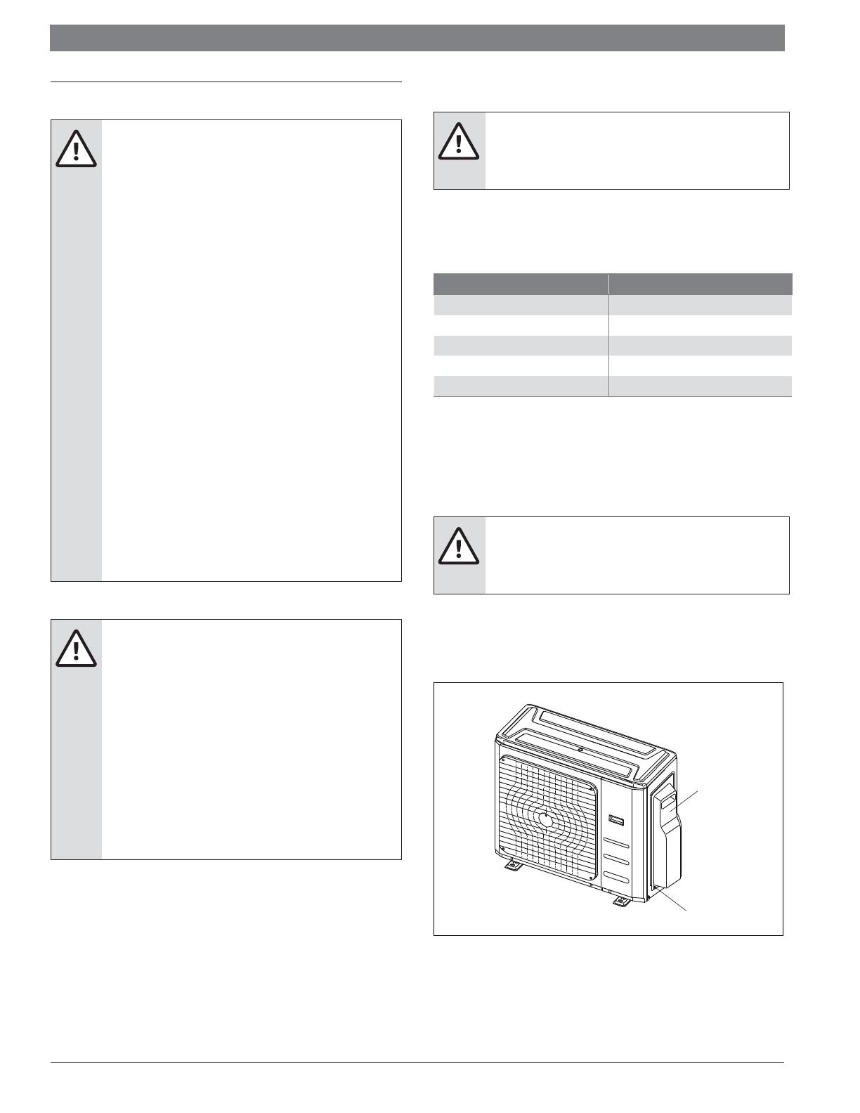
2. Remove the electric cover of the outdoor unit. If there is no cover on the
outdoor unit, disassemble the bolts from the maintenance board and
remove the protection board. (See Fig. 19)
Figure 19
Cover
Screw
3. Connect the u-lugs to the terminals. Match the wire colors/labels with the
labels on the terminal block, and fi rmly screw the u-lug of each wire to its
corresponding terminal.
4. Clamp down the cable with designated cable clamp.
18
|
Bosch Climate 5000 Series Multi Zone Ductless Air Conditioner / Heat Pump Installation Manual
05.2019 | Bosch Thermotechnology Corp.
Data subject to change
8.2 Wiring Diagrams
WARNING: ELECTRICAL HAZARD
Connect the connective cables to the terminals, as
identified, with their matching numbers on the terminal
block of the indoor and outdoor units. For example, in the
US models shown in the following diagram, Terminal L1(A)
of the outdoor unit must connect with terminal L1 on the
indoor unit.
Figure 20
Correct
Incorrect
Refer to the following fi gures for unit wiring . Run the main power cord
through the lower line-outlet of the cord clamp.
Installation Manual Bosch Climate 5000 Series Multi Zone Ductless Air Conditioner / Heat Pump | 19
Bosch Thermotechnology Corp. | 05.2019
Data subject to change
Figure 21
Two-Zone system
Magnetic ring (not supplied, optional part)
(Used to hitch to the connective cable of indoor and outdoor units
after installation.)
Three-Zone system
20
|
Bosch Climate 5000 Series Multi Zone Ductless Air Conditioner / Heat Pump Installation Manual
05.2019 | Bosch Thermotechnology Corp.
Data subject to change
Figure 22
Magnetic ring (not supplied, optional part)
(Used to hitch to the connective cable of indoor and outdoor units
after installation.)
Four-Zone system
Five-Zone system
  • Page 1 1
  • Page 2 2
  • Page 3 3
  • Page 4 4
  • Page 5 5
  • Page 6 6
  • Page 7 7
  • Page 8 8
  • Page 9 9
  • Page 10 10
  • Page 11 11
  • Page 12 12
  • Page 13 13
  • Page 14 14
  • Page 15 15
  • Page 16 16
  • Page 17 17
  • Page 18 18
  • Page 19 19
  • Page 20 20
  • Page 21 21
  • Page 22 22
  • Page 23 23
  • Page 24 24
  • Page 25 25
  • Page 26 26
  • Page 27 27
  • Page 28 28
  • Page 29 29
  • Page 30 30
  • Page 31 31
  • Page 32 32

Bosch 8733954443 Installation guide

Category
Split-system air conditioners
Type
Installation guide

Ask a question and I''ll find the answer in the document

Finding information in a document is now easier with AI