First Alert SmartBridge DVRAD0810 User manual
- Category
- Digital Video Recorders (DVR)
- Type
- User manual

USER’S MANUAL
Model
DVRAD0405/DVRAD0805/DVRAD0810/DVRAD1610/DVRAD1620

Page 2
Thank you for choosing First Alert for your security needs!
For more than half a century, First Alert has made the home-safety and security products that make
your job easier. Our products are built to the highest standard which has earned us a leadership role
in the home-safety and security product categories. We are committed to serving our customers,
from the professionals who install our products, to the families and businesses who count on them.
First Alert has been helping families and businesses stay safe for over 50 years. By having a First
Alert Security System, you’re taking the first step in protecting your home or business from damage
or theft. We’re watching, even when you’re not.
This manual is written for the SmartBridge™ DVRAD0405/DVRAD0805/DVRAD0810/DVRAD1610/
DVRAD1620 DVRs. It was accurate at the time it was completed. However, because of our ongoing effort
to constantly improve our products, additional features and functions may have been added since that
time and on-screen displays may change. We encourage you to visit our website at www.firstalert.com or
www.brkelectronics.com to check for the latest manuals (English and Spanish), firmware updates, downloads,
other security camera products and announcements. You’ll find this product line under Home Security >>
Security Cameras >>Wired Cameras.
INTRODUCTION
THANK YOU
© 2013 BRK Brands, Inc. All rights reserved. Distributed by BRK Brands, Inc., Aurora, Illinois 60504. BRK Brands, Inc. is a subsidiary of Jarden
Corporation (NYSE: JAH). First Alert® and SmartBridge™ are registered trademarks of the First Alert Trust. Due to continuing product develop-
ment, the product inside the packaging may look slightly different than the one on the package. To obtain warranty service, contact the Consumer
Affairs Division at 1-800-323-9005, Monday through Friday, 7:30 a.m. - 5 p.m., Central Standard Time.
Made in China
Welcome

Page 3
INTRODUCTION
KEY PRODUCT FEATURES
Four, eight or sixteen channel H.264 digital video recorder with Internet
remote surveillance, motion detection, PTZ and alarm control suitable
for applications such as high-end residential - new or remodel, light
commercial, small business/retail, small warehouse or small grocery
• Auto IP connection capability
• H.264 Compression & Virus free Linux O/S
• Record, playback, mobile phone live view, backup, control, & remote access
• 500 GB, 1 TB or 2TB SATA hard drive installed depending on model
• Supports smart phone live view
• User-friendly interface: DVR capable of providing 16 bit true color,
semi-transparent GUI with notes for selected menu items.
• Advanced motion detection activated recording
• 24/7 Scheduled Recording
• Network monitoring through internet access
• Supports USB or external DVD backup
• Hi-speed backup/upgrade/record via USB2.0
• PTZ camera control
• HDMI Video Out
Main Description
Product Features

Page 4
INTRODUCTION
TABLE OF CONTENTS
Section DeScription page #
1Introduction 2-5
2Safety 6
3
Product Overview 7
What is in the Box 7
DVR Controls 8-9
Front Panel 8
Back Panel 9
Remote Control 10
Mouse and Virtual Keypad 11
Camera Power Connections 12
Connecting Devices 12
4
Initial Setup - System Operation 13
System Start Up 13
Power On/Off 13
Setup Wizard Setup Wizard 14
System Setup Menu 16-29
General 16
Channel 18-19
Network 20-21
Alarm 22-25
System 26-27
Device 28-29
5
Basic Operation 30
View Layout 30
Video Adjust 31
PTZ (PAN TILT ZOOM) Camera 32
Clients 33
Snapshot 34
Record Setup 35-37
Playback 38
Clear Alarm 39
Shutdown 39

Page 5
INTRODUCTION
TABLE OF CONTENTS
Section DeScription page #
6
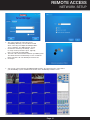
Remote Access 40
Network Setup 40-42
External Recording 43
External Playback 44
Settings 45
Advanced Setting 46
Pan Tilt Zoom 47
Setting Up Groups 48
Remote Configuration 49
Camera Settings 50
8
Appendix 51
Hard Drive Removal and Installation 51
Specifications 52
FAQ’s (Frequently Asked Questions) 53
Troubleshooting 54
Warranty 55

Page 6
SAFETY
CAUTION STATEMENTS
Safety Precautions
Safety Precautions
• Do not drop, puncture, or disassemble
the cameras or DVR.
• Do not tug on the power adapter. Use the
plug to remove it from the wall.
• Do not expose the cameras or DVR to high temperatures.
• For your own safety, avoid using the DVR when
there is a storm or lightning in your area.
• Use the cameras and DVR with care. Avoid
pressing hard on the cameras or DVR body.
• Do not use power cable if it is damaged or crushed.
Instructions for Use
• Always purchase the correct size and grade of
battery most suitable for the intended use.
• Replace all batteries of a set at the same time.
• Clean the battery contacts and also those of
the device prior to battery installation.
• Ensure the batteries are installed correctly
with regard to polarity (+ and -).
• Remove batteries from equipment that is not
to be used for an extended period of time.
• Remove used batteries promptly.
FCC Compliance Class B Digital Device
This equipment has been tested and found to comply with the limits for a Class B digital device, pursuant to Part 15 of the FCC rules. These limits are
designed to provide reasonable protection against harmful interference in a residential installation. This equipment generates, uses and can radiate radio
frequency energy and, if not installed and used in accordance with the instructions, may cause harmful interference to radio communications.
However, there is no guarantee that the interference will not occur in a particular installation. If this equipment does cause harmful interference to radio or television reception,
which can be determined by turning the equipment off and on, the user is encouraged to try to correct the interference by one or more of the following measures:
• Reorient or relocate the receiving antenna.
• Increase the separation between the equipment and receiver.
• Connect the equipment into an outlet on a circuit different from that of the receiver.
• Consult the dealer or an experienced radio or TV technician for help.
Notice: Only peripherals complying with FCC class B limits may be attached to this equipment. Operation with non-compliant peripherals or
peripherals not recommended by First Alert / BRK Brands, Inc. is likely to result in interference to radio and TV reception. Changes or modications
to the product, not expressly approved by First Alert / BRK Brands, Inc., could void the user’s authority to operate the equipment.
Important: The information shown in the FCC Declaration of Conformity paragraph below is a requirement of the FCC and is intended to supply you with information regarding the
FCC approval of this device. The phone number listed below is for FCC related questions only and not intended for questions regarding the connection or operation for this device.
FCC Declaration of Conformity for devices with the FCC logo. Responsible Party: First Alert / BRK Brands, Inc., 3901 Liberty Street Rd., Aurora, IL. 60504-
8122 Telephone: (630) 851 - 7330. Product / Model: DVRAD04, DVRAD08, and DVRAD16. We, First Alert / BRK Brands, Inc. declare under our sole responsibility
that the device to which this declaration relates: Complies with Part 15 of the FCC Rules. Operation is subject to the following two conditions: (1) this device may
not cause harmful interference, and (2) this device must accept any interference received, including interference that may cause undesired operation.
FCC Certification (if applicable)
This device contains a radio transmitter. Accordingly, it has been certied as compliant with 47 CFR Part 15 of the FCC
Rules for intentional radiators. Products that contain a radio transmitter are labeled with an FCC ID.
FCC Compliance
These symbols indicate that it is prohibited
to dispose of these batteries in the
household waste. Take spent batteries that
can no longer be charged to the designated
collection points in your community.
Disposal
Fire and Electric Shock Hazard Statement
Caution!
When working with electrostatic sensitive de-
vices such as hard disk or DVR unit, make sure
you use a static-free workstation. Any electro-
static energy coming in contact with the hard
disk or DVR can damage it permanently.
CAUTION: TO REDUCE THE RISK OF ELECTRIC SHOCK. UNPLUG
ALL POWER SOURCES, INCLUDING CAMERAS FROM THE DVR
BEFORE REMOVING COVER. FAILURE TO DO SO CAN RESULT IN
DAMAGE TO THE DVR OR ITS COMPONENTS AS WELL AS INJURY
OR DEATH.
The lightning ash with arrowhead symbol, within an equilateral triangle,
is intended to alert the user to the presence of un-insulated “dangerous
voltage” within the product’s enclosure that may be of sufcient magnitude
to constitute a risk of electric shock.
The exclamation point within an equilateral triangle, is intended to alert the
user to the presence of important operating and maintenance (servicing)
instructions in the literature accompanying the appliance.
WARNING: TO PREVENT FIRE OR SHOCK HAZARD, DO NOT
EXPOSE THIS DVR UNIT TO RAIN OR MOISTURE
CAUTION: TO PREVENT ELECTRIC SHOCK, MATCH WIDE BLADE
OF THE PLUG TO THE WIDE SLOT AND FULLY INSERT
CAUTION
RISK OF ELECTRIC SHOCK

Page 7
PRODUCT OVERVIEW
PACKAGE CONTENTS
What,s in the Box*
H.264 4,8 or 16 channel Digital DVR
with 500 GB, 1 TB or 2TB Hard Drive
DVRAD0405/DVRAD0805: 500 GB
DVRAD0810/DVRAD1610: 1TB
DVRAD1620: 2TB
USB 2.0 Mouse
WARNING
PROTECTED BY
THESE PREMISES ARE UNDER
24 HOUR VIDEO SURVEILLANCE
3 Window
Warning Decals
Installation
Software
Power Supply
for DVR
RJ45 Ethernet Cable
Quick Install Guide
Remote Control
DVR QUICK START GUIDE
POWER SPLITTER FOR
DVR AND CAMERAS
(9 way supplied with 8 Camera systems;
5 way supplied with 4 camera systems)
BNC VIDEO & DC POWER CABLE
(1 supplied with each camera)
REMOTE CONTROL &
USB 2.0 MOUSE
POWER SUPPLY
DVR & CAMERAS
RJ45 ETHERNET CABLE
Step 2: Connecting the Cameras / DVR
Connect the BNC & power from camera with BNC power cable using the side labeled
"Camera Side”
Using other side of BNC power cable connect BNC to BNC video input on DVR
Connect power cable to one of the multi power splitter ends
Plug (red) connector on power splitter to 12V DC input on DVR
Plug DVR power supply into wall outlet
Step 3: Connecting your Mouse and Ethernet Cable
Connect the USB mouse to the bottom USB slot on the back
Connect the Ethernet cable to the back of the DVR labeled either NET or RJ45
Connect the other end of the cable directly to your router, modem or high speed
internet connection input
Note: Please consult the networking section of your manual to configure the DVR for
remote viewing.
1
Back of DVR
3
ENGLISH
BACK of DVR
Step 1: Connect the DVR to your Monitor or TV
(Monitor Option)
Connect a VGA cord (not included) from your monitor to the VGA Output port on the back of your DVR.
(TV Option)
Connect the end of the BNC-RCA (BNC SIDE ONLY) cable to the back of the
DVR labeled “Video Output”
Connect the BNC-RCA (RCA SIDE ONLY) cable to an open video (yellow RCA) input on your TV/Monitor
(note the input name or number)
Turn on your TV and select the appropriate input (noted above)
1
1
2
3
1
2
3
4
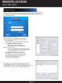
Step 4: Downloading the SmartBridge Software
Insert install CD into CD Rom Drive Double click SmartBridge.exe or let
CDRom run automatically.
Install SmartBridge Software.
On your computer desktop, Double click installed Smartbridge Software Icon.
Select the Connect Tab. Enter Auto ID DVR Code (On DVR system, right click and
select “Net Status” to obtain Auto ID DVR Code). Password is default 123. Select
Login to start viewing your Smartbridge security system remotely.
2
1
3
4
5
1
2
3
VGA
1
1
2
2
Product Contents
Power
IR
Rec
MENU 1 2 3 4
1 2 3 4
ESC
DVR
CAMERA(S)
STICKERS
WARNING
PROTECTED BY
THESE PREMISES ARE UNDER
24 HOUR VIDEO SURVEILLANCE
3
2
3
4
5
1
(Attach for each camera)
(5 or 9-Way Power Splitter)
Go to firstalert.com and search for model # to find complete instruction manual of
your First Alert DVR.
© 2012 BRK Brands, Inc. All rights reserved. Distributed by BRK Brands, Inc., Aurora, Illinois
60504. BRK Brands, Inc. is a subsidiary of Jarden Corporation (NYSE: JAH). First Alert® is a
registered trademark of the First Alert Trust. Due to continuing product development, the product
inside the packaging may look slightly different than the one on the package. To obtain warranty
service, contact the Consumer Affairs Division at 1-800-323-9005, Monday through Friday, 7:30
a.m. - 5 p.m., Central Standard Time.
www.firstalert.com
iPhone, iPad, Android Compatible*
1
2
3
4
* iPhone and iPad are registered trademarks of Apple Inc. Android is a trademark of Google, Inc.
9-way splitter
or two splitters for 16
channel
60’ BNC Video &DC Power Cables
(One for each camera. Varies with kits depending
on number of cameras included.)

Page 8
PRODUCT OVERVIEW
DVR CONTROLS
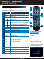
Front Panel
item Function control DeScription
1(1) IR remote receiver Direct remote towards this position when using DVR
2Power indicator light A green light indicates power is on
3Record indicator light A green flashing light indicates recording
Buttons 1-4(8)(16) Camera Selection
410+ Press for camera selection of channels 10-16 (on 16 channel DVR only)
5Menu Enter menu setup
6ESC Brings system previous selection
7Left In menu mode: moves to highlight next section
8Up In live mode: rotates between single , quad, eight or nine camera screen
9Down In live mode: rotates between single , quad, eight or nine camera screen
10 Right In menu mode: moves to highlight previous section
11 OK Press to make selection
12 Sleep On 16 Channel DVR only
1
2 12 4
3 6
8 10
115
7
9
8 Channel DVR
16 Channel DVR
1
2 12
3
8 10
115
7
9
4 Channel DVR
1
2 12
3
8 10
115
7
9

Page 9
PRODUCT OVERVIEW
DVR CONTROLS
Back Panel
item Function DeScription
1 Alarm 4 alarm inputs; 1 alarm output
2 VGA Output For connecting to VGA monitor
3HDMI Output For connecting to HDMI monitor
4 USB/Mouse Use Lower USB port for mouse connection; Use Upper USB port for USB flashdrive or backup
5NET For connecting RJ45 ethernet cable to PC or router
6 RS485 For connecting PTZ cameras
7 Power Switch Power On/Off
8 Power Supply For connection to power cord +12V DC
9 Audio Input For connecting audio signal from audio capable cameras or self powered microphones (RCA jacks)
10 Video Input For connecting video signal from cameras (BNC)
11 BNC Output For connecting to a BNC monitor
12 RCA Audio Out For connecting to a speaker or amplifier
13 Ground Ground Connection
12
4 6 85
7
8
11
13
10
312
4 Channel DVR
8 Channel DVR
16 Channel DVR
1
2 4 6 85
7
8
11
13
10 3
12
1
4 6 85
7811
13
10 3
12 2

Page 10
Remote Control
Remote Control Operation
The remote control is the secondary input device for navigating the system’s interface.
In device operation, the MENU key has the same function as “left click” of the mouse.
Any button not identified is not used.
PRODUCT OVERVIEW
REMOTE CONTROL
Directions for Installing/
Changing Batteries
1. Open battery compartment on back of
Remote and insert (2) Alkaline AAA batteries
(provided.)
2. Ensure all batteries are installed correctly
with regard to polarity (+ and -.)
3. Remove batteries from Remote if it is not to
be used for an extended period of time.
4. Remove used batteries promptly and
replace all batteries of a set at the same
time.
5. Always purchase the correct size and grade
of battery most suitable for intended use.
item Function DeScription
1Power Click power for about 3-5 seconds to shut down the DVR.
2Numeric
Buttons
Press to Select channel to view; use to input numerical information in
appropriate screens
3
NAVIGATION BUTTONS
Press to make selection
Press to cursor up; in PTZ mode, press to pan camera up
Press to move cursor down; in PTZ mode, press to pan camera down
Press to move cursor left; in PTZ mode, press to pan camera left
Press to move cursor right; in PTZ mode, press to pan camera right
4
PLAYBACK CONTROLS
Playback Search Recordings
Play Play Recording (resumes after pause)
Pause Pause Playback in recording mode
Frame Playback by frame
Fast Forward Press to fast forward
Fast Backward Press to fast backward
Play Slowly Press to play video slowly
Stop Press to stop playback
Record Press to record video (allows to select any or all cameras)
5Zoom – (For PTZ cameras only) Press to zoom out
6Zoom + (For PTZ cameras only) Press to zoom in
7Menu Quick access menu
8All Scroll through different view modes
910+ Press for camera selection of channels 10-16
10 ESC Exits Page/Command
11
DEV
(To use the remote for
more than one DVR)
Allows setting the remote default ID
8
10
7
9
5 6
2
1 11
3
4

Page 11
PRODUCT OVERVIEW
MOUSE AND VIRTUAL KEYPAD
Mouse Operation with this DVR
The mouse is the primary input device for navigating system menus.
NOTE: Unless otherwise noted, all system functions described
in this manual are achieved through mouse input.
To use a mouse with the system:
Connect a USB mouse to the USB MOUSE port on back panel of the system.
NOTE: Only the USB 2.0 port on the back panel (Upper USB port)
is designed for data backup to a USB flash drive. Do not connect a
USB flash drive to the USB MOUSE port. (Lower USB port)
Use the mouse buttons to perform the following:
1 Left-Button:
• Click to select a menu option
• During live viewing in split-screen double-click on a channel
to view the selected channel in full-screen
• Double-click the channel again to return to split-screen view
• Selecting letter or number on the virtual keypad
2 Right-Button:
• Click to open the Quick Access Menu
• Exits any window
• Exits any menu or re-opens previous menu
3 Scroll-Wheel:
• No function
Mouse Controls
REAR of DVR
Connect Mouse &
USB Drive
2
1
Mouse Button
Operation
3
Virtual Keypad
Virtual Keypad
To enter text or numerical data, the system uses a virtual keypad. In fields
where letters or numbers can be entered, you can switch between various
formats – numbers, upper case (ABC) and lower case (abc). Note you can
access all numbers when in the “Letters” virtual keypads. See below.
Numbers Letters

Page 12
PRODUCT OVERVIEW
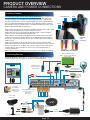
CAMERA AND POWER CONNECTIONS
Connecting Devices
Splitter -
4/8 camera
1 Power
Power to DVR
Power
from 120V
DC Converter - 12V
VGA to PC Monitor or TV
BNC to Security Camera Monitor
(Not included)
RJ45 Ethernet to
Router and Internet
PTZ & Alarm
Connections
(Cameras not
included)
Follow this diagram to make device connections. Note, some devices are not
included with this kit. See “What’s in the Box” for included devices.
RCA Audio Out to
Powered Speakers
(Not included)
Back Panel
Connect Mouse &
USB Drive
Smartphone
through Mobile
Internet Setup
(Smartphone Not
included)
Video to DVR
Channels 1-8
Video to Camera
Power to Camera
AV Cable: BNC/DC Power
(1 per Camera)
RCA Audio In from Audio
Cameras or Powered
Microphone
(Not included)
Splitter Cable
Installing Cameras
Installing Cable-Safe Mounting Bracket
Decide if the camera is to be wall or ceiling mounted and if cable will be fed
through mounting surface hidden directly behind the bracket or fed through
the side of the bracket so cable is exposed. Mark area where you will drill your
hole. The Cable-Safe Mounting Bracket has three Adjusting Points. 1) Rotates
Bracket 360° relative to mounting surface, 2) Adjusts bracket hinge 180° and 3)
Rotates camera body 360° to level image.
Step 1: Select the position for the camera and drill your hole for the cable. Feed
cable through mounting surface. Mount bracket to surface.
Step 2: Aim camera at target and using Adjusting Points 1 and 2 in tandem
position camera. Tighten Ring and Thumb Screw.
Step 3: Rotate camera body using Adjusting Point 3 to the proper view angle
making sure the Camera Shield is always on top and parallel to the ground so
the image is level in the Live View Screen. See “Camera Orientation” Info box.
Tighten screw.
Step 4: Attach proper length of cable and run from camera to DVR location.
Note: Power cable ends are different. Be sure the correct power connector end
matches “To Camera” or “To DVR”. Tip - Connect cable at camera end before
running cable to verify orientation is correct. Also, see Information box on
“Longer Cable Runs”.
Step 5: Check camera orientation via the Live View screen. Adjust as required.
Screw
Thumb Screw Ring
Slot for
exposed
cable
installation
To DVR To Camera
Verify Cable Orientation
2 1
3
Use First Alert Cameras Only Use First Alert Power Supply Only

Page 13
Power On/Off
To power the system On/Off, connect the power cable to the DC 12V port on the rear panel. Press the toggle
switch to the on position in the back of the DVR. At startup, the system performs a basic system check
and runs an initial loading sequence. After a few moments, the system loads a live display view.
User Login
Password
ATTENTION: By default, passwords are disabled on the system. You
do not need to enter a password when accessing any system menus.
However, for security purposes, it is highly recommended to enable
passwords on the system using the Password Menu. See “Password”
section for details on setting up passwords. Right click and
select Login. No password is required when no password is
set up. Right click again to show the quick access menu
Quick Access Menu
When using the mouse, use the Quick Access Menu to
access several system options, including the System
Setup Menu. Select one of the following options:
• System Setup: Opens the main system menu
• View Layout: Provides a choice of viewing channels on the
monitor
• View 1: Allows viewing of 1 channel
• PIP: Allows viewing of 2 channels,
Picture in Picture
• View 4: Allows viewing of 4 channels
• View 8: Allows viewing of channels 1
through 8, with channel 1 in large view mode
• Split 9: Allows viewing of
channels in a 3 x 3 channel grid
• Split 16: Allows viewing of
channels in a 4 x 4 channel grid
• Video Adjust: Adjust video image settings by channel
• PTZ: Opens the PTZ control menu
• Clients: Network user status
• Snapshot: Allows you to take a photo of the
channel that the cursor is on, and save to HDD
• Photos: Review save Snapshots, and upload to USB drive
• Record Setup: Access to recording settings
for each channel, begin manual recording
• Playback: Open the Search Menu
and playback recorded video
• Clear Alarm: Cancel alarms
• Shutdown: Allows a choice of logging out,
powering down or restarting the DVR system
INITIAL SETUP
SYSTEM OPERATION
Main Viewing Screen
User Login Menu
Power Switch
NOTE: Powering down stops the system. The power LED is still on. The only way to fully power down
the system is by turning the power off & on with the power switch on the back of the DVR.
System Start Up
Powering your DVR and Cameras
The power supply included with the DVR is rated for 5 amps. Normally, this is enough to power both the
DVR and supplied cameras. However, using aftermarket cameras or a larger number of cameras may sur-
pass the capability of the power supply, causing the systerm to shut down. Most devices should be marked
with the Amperage rating, but some may be marked by wattage. In this case, Amp usage can be found by
dividing Watts by Volts, or A=W/V. The power supply should be upgraded if it surpasses 80% of its rating
(i.e., 4 amps for a 5 amp power supply), to compensate for momentary spikes in current draw. Note: One Amp equals 1000 milliamps

Page 14
INITIAL SETUP
SETUP WIZARD
Setup Wizard
Quick Startup
After the initial system power up,
the system will ask for a login. The
default user is “abc” and there is no
password. Simply click login, after
which the Setup Wizard will start.
Clicking on “Next” will bring you to
the next page. “Cancel” will exit the
Wizard.
• Device ID
Enter a number between
0 and 255 to identify the
DVR when used with
other DVRS
• Language
Choose from the
dropdown menu to set
your preferred language
• Date Format
Choose from the
dropdown menu to set
your preferred date
format
• Set Date
Set the year, month
and day here
• Set Time
Set the hour,
minute and second
here
• Timezone Setting
Set the timezone
according to Prime
Meridian time
• PPPoE
Click “Set” to setup the
DVR to comminucate
over DSL or 3G wireless
networks. You will need
the account info from your
Service Provider
• IP
The DVR’s IP address can
be manually set here
• NetMask
The IP Subnet Mask
can be manually set
here
• Gateway
Set the Gateway IP
address here
• DNS
Select the DNS
IP address for the
network here
• Device Port
Used to select an open
port on a network router
for the DVR to access
• Automatic (DHCP)
Click here to automatically
assign an IP address to
the DVR once connected
to a network
Continued on next page

Page 15
INITIAL SETUP
SETUP WIZARD
• Resolution (Main)
Choose between
“None(Camera Default)”,
“CIF(352x288)” or
“D1(720x480)” resolutions
• kbps (Main)
Choose transmission rate
for camera channel
NOTE: A higher kbps will
result in larger video files
• Resolution (Minor)
Choose between
“None(Main Setting
Default)”, “QCIF(176×144)”
or “CIF(352x288)”
resolutions over network
• kbps (Minor)
Choose transmission
rate for camera
channel over a
network connection
• Fluency (Minor)
Selects the frame rate that is
transmitted over the network.
A higher frame rate will
increase network data rate
• Number
ID number of the particular
drive device
• Capacity
Drive device’s storage
total capacity
• Used
Amount of currently
stored data on drive
device • Status
Show status of
Hard Drive
• Format
Will format a selected
drive. NOTE: This will
erase all data on the
drive
• Refresh
Select to update
display of connected
disk drives
• Type
Displays the drive device
type, “HD” for Hard Drive,
“U-Drive” for USB Drive
Finishing the Wizard
After the Drive Device the screen, the Wizard will ask if the Wizard should be launched the next time the DVR boots up. After
clicking “Finish” the system will ask if you would like to run the “interactive demo.” Click “Ok” to run the demo.

Page 16
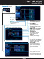
SYSTEM SETUP
GENERAL MENU
System Setup
General Menu
Path: System Setup>General
After the system powers up, and the user is logged
in, the Right Click Menu can be accessed. To access
basic System Settings, select the first option,
“System Setup.”
To open the System Setup Menu: Right-click
anywhere on-screen to open the Quick Access Menu
and select System Setup (mouse only), or press the
Menu and select System Setup on the remote control
or front panel of the system.
NOTE: If passwords are enabled on the system, enter
the username and password when prompted. • Language
Select your preferred language
from the dropdown menu
• NTSC/PAL
Change the video the standard
between NTSC (North
America) and PAL (Europe and
rest of world)
NOTE: Changes take effect
after rebooting the DVR
• Camera
Select camera feed
• Transparency
Select sppearance of
onscreen menus
• Display Device ID
Toggle device ID
display in upper right
corner of monitor
• Display Wizard for Startup
Toggle to activate Quick Setup
Wizard when system boots up.
• Wizard
Click here to begin
Quick Setup Wizard
at any time
• Interactive Demo
Click to begin demo which
highlights system functions
and capabilities
• VGA Resolution
Select display resolution

Page 17
SYSTEM SETUP
GENERAL MENU
• Date Format
Set the date format according to
your local preference
• Set Date
Enter the current date here
• User Group
Toggles User List between local
users and network users
• User List
Once a user group is selected,
from above, the users belonging
to that group will be displayed.
Using the Add, Edit and Delete
buttons, the list and users can
be changed
• Automatic Logout
Toggles wether or not user is
logged out after a set time
• Set Time
Enter the current time here
• Timezone Setting
Set your local time-zone here
• Auto Synchronize Time
Adjusts and sets system time to
match network server time
• Enable DST
Set time to adjust
for Daylight Savings
Why Set a Date & Time?
It’s important to set the proper date and time before continuing so that you can easily locate recorded events.
Inaccurate dates and times on files may affect their admissibility as evidence in court. In addition, when
changing current time settings, to avoid possible confusion with the time stamps on recorded and currently
recording files, stop all ongoing recording processes before altering the system time and restart recording
using the new settings.
• Wait [x] Min
Adjusts time interval before user
is logged out if Automatic Logout
is selected. Enter the desired wait
time in minutes in the box
General Menu (Continued)
Path: System Setup>General

Page 18
Channel Menu
Path: System
Setup>Channel
Use the Channel
Menu and its
submenus to adjust
Channel Display
settings, including
resolution, menu
display position,
privacy masks, audio
settings
• View Setting
This tab adjusts certain
channel appearance options
• Copy
Will copy one
channel’s settings
to the rest of the
channels.
NOTE: Channel
Name will not be
copied
• Default
Will reset all
channels to
their default
settings
• Arrange Views
This will open a 16-view
screen where the different
channels can be rearranged on
the display to your preference
NOTE: The system will ask to
reboot after saving changes.
• Channel
The channel
number
according
to view
arrangement
• Channel
Name
The channel
name can be
changed here,
i.e., CH01 will
be displayed as
Front Hall
• OSD Pos.
Choose where
channel stats
are displayed
• Hide Video
Check this if
you do not
want the
channel to be
displayed.
NOTE:
Recording and
other functions
will still operate
for the channel
• DVR Port
Shows which
port the camera
for the channel
is plugged into
on the bacl of
the DVR
• Privacy Mask
This tab allows the creation of masks to block certain
areas from being recorded
• Copy, Default, Arrange View
Operate just as in the View Setting tab
SYSTEM SETUP
CHANNEL MENU

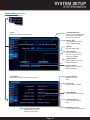
Page 19
• Volume
Toggles volume level for audio
channels
• Resolution (Main)
Choose between
“None(Camera Default)”,
“CIF(352x288)” or
“D1(720x480)” resolutions
• kbps (Main)
Choose transmission rate
for camera channel
NOTE: A higher kbps will
result in larger video files
• Resolution (Minor)
Choose between
“None(Main Setting
Default)”, “QCIF(176×144)”
or “CIF(352x288)”
resolutions over network • kbps (Minor)
Choose transmission
rate for camera
channel over a
network connection
• Fluency (Minor)
Selects the frame rate that is
transmitted over the network.
A higher frame rate will
increase network data rate
• Audio
Audio channel number
• Audio Compress
Close or Open audio compression
• Audio Monitoring
Close or Open audio monitoring
• Bind with Audio
Choose which video channel the
audio will match up with
Channel Menu (Continued)
Path: System Setup>Channel
SYSTEM SETUP
CHANNEL MENU

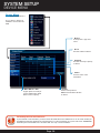
Page 20
Network Menu
Path: System Setup>Network
Using the Network menu, settings for the DVR’s
connection to a network and the internet can be
changed and adjusted.
• PPPoE
Click Set to setup the DVR to comminucate over
DSL or 3G wireless networks. You will need the
account information from your Service Provider
• IP
The DVR’s IP address can
be manually set here
• NetMask
The IP Subnet Mask can
be manually set here
• Gateway
Set the Gateway IP
address here
• DNS
Select the DNS IP address
for the network here
• Device Port
Used to select an open
port on a network router
for the DVR to access
• Automatic (DHCP)
Click here to automatically
assign an IP address to
the DVR once connected
to a network
• MAC
This is the MAC address
for the DVR
• Device ID
This is the SmartBridge
Device ID for the DVR
• Status
Network status of the
DVR
SYSTEM SETUP
NETWORK MENU
Page is loading ...
Page is loading ...
Page is loading ...
Page is loading ...
Page is loading ...
Page is loading ...
Page is loading ...
Page is loading ...
Page is loading ...
Page is loading ...
Page is loading ...
Page is loading ...
Page is loading ...
Page is loading ...
Page is loading ...
Page is loading ...
Page is loading ...
Page is loading ...
Page is loading ...
Page is loading ...
Page is loading ...
Page is loading ...
Page is loading ...
Page is loading ...
Page is loading ...
Page is loading ...
Page is loading ...
Page is loading ...
Page is loading ...
Page is loading ...
Page is loading ...
Page is loading ...
Page is loading ...
Page is loading ...
Page is loading ...
Page is loading ...
-
 1
1
-
 2
2
-
 3
3
-
 4
4
-
 5
5
-
 6
6
-
 7
7
-
 8
8
-
 9
9
-
 10
10
-
 11
11
-
 12
12
-
 13
13
-
 14
14
-
 15
15
-
 16
16
-
 17
17
-
 18
18
-
 19
19
-
 20
20
-
 21
21
-
 22
22
-
 23
23
-
 24
24
-
 25
25
-
 26
26
-
 27
27
-
 28
28
-
 29
29
-
 30
30
-
 31
31
-
 32
32
-
 33
33
-
 34
34
-
 35
35
-
 36
36
-
 37
37
-
 38
38
-
 39
39
-
 40
40
-
 41
41
-
 42
42
-
 43
43
-
 44
44
-
 45
45
-
 46
46
-
 47
47
-
 48
48
-
 49
49
-
 50
50
-
 51
51
-
 52
52
-
 53
53
-
 54
54
-
 55
55
-
 56
56


First Alert SmartBridge DVRAD0810 User manual
- Category
- Digital Video Recorders (DVR)
- Type
- User manual
Ask a question and I''ll find the answer in the document
Finding information in a document is now easier with AI
Related papers
-
First Alert 6 Channel Dvr With 2 User manual
-
-
First Alert DC4205-420 User manual
-
Digital View PRO-DC8410-520 User manual
-
BRK HS-4705-400 User manual
-
-
-
-
-
Other documents
-
 InterVision XPR-4004E User manual
-
 Visco VIS308D User manual
-
NIGHT OWL F series User manual
-
-
-
-
-
Digimerge Touch DH200P Series User manual
-
Epson DH200 User manual
-
Proximus P16-41438 User manual

