Page is loading ...

Installation and Operation Manual
Standard Chassis Models
115-Volt:
208-230-Volt:
Room Air Conditioners
SS08, SS10, SS12, SS14, SM15
SS12, SS16, SM18, SM21, SM24
SL22, SL24, SL28, SL36
115-Volt:
208-230-Volt:
YS10
ES12, ES16, YS12, EM18
YM18, EM24, EL36, YL24
93001010_00

2
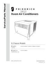
Model information can be found on the name
plate behind the front cover.
Please complete and mail the owner
registration card furnished with this product,
or register online at www.friedrich.com.
For your future convenience, record the
model information here.
MODEL NUMBER
SERIAL NUMBER
PURCHASE DATE
Register your air conditioner
your unit to assure quiet operation, the greatest circulation of cool, dry air, and the most economic operation.
MODEL NUMBER
YS10M10A
SERIAL NUMBER
LICY00008
VOLTS 115
60 HZ / 1 PH
VOLTS MIN 108
COOLING
BTH/HR 6500
EER 12.0
AMPS 8.0
HEATING
BTH/HR 6500
EER 10.4
AMPS 7.0
REFRIGERANT
30.1 OZ R410A
XXXXXXXXX
600 PSIG HS
300 PSIG LS
XXXXXXXXXX
XXXXXXXXX
XXXXXXXXXX
XXXXXXXXXX
FUSE PROTECTED
CIRCUITS USE 15A
TIME DELAY FUSE
X XX
XXXXX
XXXXXXXXXX
UL
AIR CONDITIONING CO.
SAN ANTONIO, TEXAS
ASSEMBLED IN MEXICO
MODEL NUMBER
YS10N10
SERIAL NUMBER
LICY00008
AIR CONDITIONING CO.
SAN ANTONIO, TEXAS
ASSEMBLED IN MEXICO
THANK YOU, on behalf of our entire company,
for making such a wise purchase.

3
Safety Precautions ...................................................................................................................................................................................................................4
Unpacking Instructions.............................................................................................................................................................................................................5
WARNING: Before Operating Your Unit ..................................................................................................................................................................................6
Standard Filter Cleaning / Installation Instructions ..................................................................................................................................................................7
Premium Carbon Filter Installation Instructions .......................................................................................................................................................................8
Control Panel Operation ......................................................................................................................................................................................................... 9
New Kühl Control Options ......................................................................................................................................................................................................10
Control Panel Operation Instructions ...............................................................................................................................................................................................11
Remote Control Operation .....................................................................................................................................................................................................20
Remote Effectiveness ............................................................................................................................................................................................................20
Installation Instructions ..........................................................................................................................................................................................................23
Standard Window Installation ................................................................................................................................................................................................25
Cord Routing Change ............................................................................................................................................................................................................34
Through-the-Wall Installation .................................................................................................................................................................................................36
Final Inspection & Start-up Checklist.....................................................................................................................................................................................40
Routine Maintenance .............................................................................................................................................................................................................41
Service and Assistance .........................................................................................................................................................................................................41
Available Accessories ............................................................................................................................................................................................................41
Troubleshooting Tips ..............................................................................................................................................................................................................42
Addendum 1 ...........................................................................................................................................................................................................................44
..........................................................................................................................................................................................22
Warranty ..... ...........................................................................................................................................................................................................................45
Table of Contents

4
Safety Precautions
NOTICE
CAUTION
WARNING
Your safety and the safety of others are very important.
We have provided many important safety messages in this manual and on your appliance. Always read and obey all
safety messages.
This is a safety Alert symbol.
This symbol alerts you to potential hazards that can kill or hurt you and others.
All safety messages will follow the safety alert symbol with the word “WARNING”
or “CAUTION”. These words mean:
Indicates a hazard which, if not avoided, can result in severe personal injury or
death and damage to product or other property.
Indicates a hazard which, if not avoided, can result in personal injury and
damage to product or other property.
All safety messages will tell you what the potential hazard is, tell you how to reduce the chance of injury, and tell you
what will happen if the instructions are not followed.
Indicates property damage can occur if instructions are not followed.
WARNING
Refrigeration system
under high pressure
Do not puncture, heat, expose to flame or
incinerate.
Only certified refrigeration technicians should
service this equipment.
Only use gauge sets designed for use with
R410A. Do not use standard R22 gauge sets.
R410A systems operate at higher pressures
than R22 equipment. Appropriate safe
service and handling practices must be used.

5
Unpacking Instructions
STEP 1. Cut all 4 packing straps.
STEP 2. Remove wooden shipping bar dividers.
STEP 3. Remove top foam pads.
STEP 4. Slowly remove outer box, careful not to loosen decorative front.
STEP 5. Slide the foam front support forward
STEP 6. Carefully lift decorative front box from foam front support
STEP 7. Remove decorative front and set safely aside

6
Make sure the wiring is adequate for your unit.
If you have fuses, they should be of the time delay type. Before you install
or relocate this unit, be sure that the amperage rating of the circuit breaker
or time delay fuse does not exceed the amp rating listed in Table 1.
DO NOT use an extension cord.
The cord provided will carry the proper amount of electrical power to the
unit; an extension cord may not.
Make sure that the receptacle is compatible with
the air conditioner cord plug provided.
Proper grounding must be maintained at all times. Two prong receptacles
The grounded receptacle should meet all national and local codes and
ordinances. You must use the three prong plug furnished with the air
conditioner. Under no circumstances should you remove the ground
prong from the plug.
Test the power cord
All Friedrich room air conditioners are shipped from the factory with a
Leakage Current Detection Interrupter (LCDI) equipped power cord. The
LCDI device on the end of the cord meets the UL and NEC requirements
for cord connected air conditioners.
To test your power supply cord:
1. Plug power supply cord into a grounded 3 prong outlet.
2. Press RESET (See Figure 1).
3. Press TEST, listen for click; the RESET button trips and pops out.
4. Press and release RESET (Listen for click; RESET button latches
and remains in). The power cord is ready for use.
MODEL
CIRCUIT RATING
OR TIME DELAY
FUSE
REQUIRED
WALL
RECEPTACLE
AMP VOLT NEMA
NO.
SS08, SS10
SS12, SS14
YS10, SM15
15 125 5-15R
SS12, SS16
SM18, SM21 15 250 6-15R
SM24
, SL28
ES12, ES16
YS12, SL24
20 250 6-20R
SL36, EM18
EM24,
EL36
YM18, YL24
30 250 6-30R
Table 1.
WARNING
Electrical Shock Hazard
Make sure your electrical receptacle has the
same configuration as your air conditioner’s
plug. If different, consult a Licensed Electrician.
Do not use plug adapters.
Do not use an extension cord.
Do not remove ground prong.
Always plug into a grounded 3 prong oulet.
Failure to follow these instructions can result in
death, fire, or electrical shock.
NOTICE
Do not use the LCDI device as an ON/OFF switch.
Failure to adhere to this precaution may cause
premature equipment malfunction.
Once plugged in, the unit will operate normally without the need to reset
the LCDI device. If the LCDI device fails to trip when tested or if the power
supply cord is damaged, it must be replaced with a new power supply cord
from the manufacturer. Contact our Technical Assistance Line at (800)
541-6645. To expedite service, please have your model number available.
Figure 1
FRR072
WARNING:
TEST BEFORE EACH USE!
1. PRESS REST BUTTON.
2. PLUG LCDI INTO POWER
RECEPTACLE.
3. PRESS TEST BUTTON,
RESET BUTTON SHOULD
POP UP.
4. PRESS RESET BUTTON
FOR USE.
DO NOT USE IF ABOVE TEST
FAILS.
WHEN GREEN LIGHT IS ON.
IT IS WORKING
PROPERLY!
RESET
TEST
SL22

7
FRR071
Standard Filter Cleaning / Installation Instructions
STEP 1.
FRR047
FILTER
FILTER
GRIP
STEP 3. Swing the front frame open. Clean the front frame by washing
STEP 2.
NOTE:
FRR052
HANDLE
FILTER
GRIP
FRR048
TOP TAB
FRONT
FRAME WITH
STANDARD
MESH FILTER
A
Figure 2 Figure 4
Figure 5
Figure 3
STEP 4.
NOTE: the tab in the frame stops the handle from sliding in, slide the
handle from the other direction. Do not force the handle into
the frame.
STEP 5. the inside of the front door.

8
STEP 1.
STEP 2. in Figure 4.
STEP 3.
as shown in Figure 6.
NOTE: Make sure the frame with the mesh is facing towards you.
Premium Carbon Filter Installation Instructions
STEP 4.
NOTE:
STEP 5. and slide the assembly into the unit as per the instructions
on the door.
NOTE: the tab in the frame stops the handle from sliding in, slide the
handle from the other direction. Do not force the handle into
the frame.
Figure 7
FRR051FRR050
Figure 6
FRONT FRAME WITH
MESH FILTER

9
2 DIGIT DISPLAY
Shows Setting for:
- Set Point (Temperature)
- Room Temperature
- Clock (AM/PM)
ON / OFF
Turns unit on/off
SYSTEM
Cycles between
AUTO, HEAT,
COOL, or FAN
ONLY
(if equipped)
FAN MODE
Sets fan to either:
- Cycle automatically
- Run continuously
HEAT
FILTER
Check / Clean
AUTO SPEED
Automatically
selects best fan
cooling speed
$MART OPERATING
(if equipped)
FAN SPEED
Selected fan speed
COOL FAN
ONLY CONTROL
LOCKED
WI-FI
OPERATING
(if equipped)
WAIT
TEMPERATURE
Increment UP
TEMPERATURE:
Increment DOWN
SCHEDULE ON
TIMER / SCHEDULE
Turns ON or OFF
TIMER ON
IR WINDOW
:
Do not block
Let’s check out how to control your air conditioner. On the control panel, just above the POWER , is a liquid crystal display (LCD). All of the control panel function
buttons and mode icons can be viewed in Figure 8.
Power On – Press the button to turn on the air conditioner. The power button illuminates to indicate that the power is on. The backlight on the power switch
will automatically dim to 20% intensity after 15 seconds of inactivity. The remote control can also be used to turn power ON / OFF (See Remote Control).
Display
inactivity, the display dims to 20% intensity. After an additional 120 seconds, the display switches off. Touching any button automatically changes the display
to full brightness.
There are three control push buttons on each side of the display.
Control Panel Operation
AUTO
Automatically switches
between cool & heat
SET POINT
AUTO SPEED
F
FAN
SPEED
FAN
MODE
SYSTEM
TIMER
SCHEDULE
FAN SPEED
Sets fan speed:
LOW, MED,
HIGH or AUTO
(if equipped)
AUTO
SET POINT
ROOM TEMP
CHECK
FILTER
AUTO SPEED
$MART
F
C
ON OFF
SCHEDULE
AM
PM
AUTO FAN
CONTINUOUS
Figure 8

10
The new Kühl gives you a variety of options for control, programming, and
scheduling including wireless capabilities
. The new FriedrichLink™ Adapter (sold seperately) allows you to conviently
control, program and monitor your air conditioning unit remotely from a
smartphone or computer.
retailers or www.friedrich.com. See FriedrichLink™ Adapter section on
www.friedrich.com for complete details.
New Kühl Control Options
Pre-Programmed Scheduling Options:
Your unit’s digital control comes equipped with a 24-hour timer and two pre-
programmed 7-day energy management options.
24-Hour Timer
The 24-hour timer allows you to turn the unit off and on at pre-set times by
setting an on and off time on the unit control panel. (See page 12 for details on
timer set-up.)
Pre-programmed Energy Management
Your unit comes from the factory with two (2) Pre-programmed Energy
Management settings are shown in Addendum 1 (Residential & Commercial
Schedule Table).
Energy Management Schedule Options are:
1. Residential Schedule – 40 Hr. Work Week
2. Commercial Schedule – 5-Day Business Week
The “Residential” (40 Hr. Work Week) Schedule has four (4) time periods: 06:00,
08:00, 18:00, and 22:00. This option will cause your Kühl Q unit to raise the room
temperature temporarily to 85°F during the hours when most people are away
at work, lower them again to 78°F prior to the time when most people will return
home, and then raise slightly to 82°F to maintain a comfortable temperature
overnight.
The “Commercial” (5-Day Business Week) Schedule has two (2) time periods:
07:00 and 18:00. This option will cause your air conditioner to raise temperatures
to 84°F after typical working hours and on weekends when commercial spaces
are typically unoccupied.
(See Control Panel Operation Instructions Section)
Customizable Programming Options:
Customizable schedules, with up to four temperature adjustments per day, can
either be uploaded to the unit via the air conditioner’s built-in micro USB interface
or conveniently transmitted wirelessly using the new FriedrichLink™ Adapter
accessory, greatly simplifying the programming of one or multiple units.
See Figure 9.
See www.friedrich.com for complete details on
FriedrichLink.
Figure 9
Wireless Programming and Control:
FriedrichLink™ Adapter accessory available through Friedrich authorized
MODEL NUMBER
YS10M10A
SERIAL NUMBER
LICY00008
VOLTS 115
60 HZ / 1 PH
VOLTS MIN 108
COOLING
BTH/HR 6500
EER 12.0
AMPS 8.0
HEATING
BTH/HR 6500
EER 10.4
AMPS 7.0
REFRIGERANT
30.1 OZ R410A
XXXXXXXXX
600 PSIG HS
300 PSIG LS
XXXXXXXXXX
XXXXXXXXX
XXXXXXXXXX
XXXXXXXXXX
FUSE PROTECTED
CIRCUITS USE 15A
TIME DELAY FUSE
X XX
XXXXX
XXXXXXXXXX
UL
AIR CONDITIONING CO.
SAN ANTONIO, TEXAS
ASSEMBLED IN MEXICO
FriedrichLink™ Adapter

11
SYSTEM - The SYSTEM button allows you to sequentially select up to four
modes of operation:
AUTO
HEAT Not available on some models
FAN ONLY
COOL MODE
SET POINT
F
AUTO FAN
FRR103
FRR105
SET POINT
F
AUTO FAN
FRR104
- AUTO-, COOL or HEAT or FAN ONLY mode,
you can also select FAN MODE, FAN SPEED, TIMER SCHEDULE,
. The SYSTEM MODE does not change.
HEAT MODE
FAN ONLY MODE
AUTO FAN (No Cooling Demand)
When in the AUTO FAN mode, the fan only operates when the system has
a demand to cool or heat the room. Note: the fan is off (no fan speed icon),
indicating no command for cooling or heating.
SET POINT
F
AUTO FAN
FRR112
SET POINT
F
AUTO FAN
FRR106
System has a demand for cooling. The fan is operating at a medium speed.
When fan speed AUTO FAN mode (SYSTEM mode AUTO, COOL or HEAT) is selected, fan speed automatically varies depending on the difference between
the unit’s set point on the control panel and the actual room temperature. When the system detects a wide difference between the set point and the actual
room temperature the fan speed increases to HIGH for a period of time. The fan speed decreases, in step, as the temperature difference decreases. When the
room temperature matches the system's set point, fan speed returns to the original setting.
FAN MODE – The FAN
MODE button allows you to select between AUTO FAN and
CONTINUOUS modes.
AUTO FAN (Cooling Demand)
Control Panel Operation Instructions
COOL
Not available on some models
- AUTO -
AUTO MODE
SET POINT
F
AUTO FAN
FRR204
- AUTO -
FAN SPEED - Depending on your model, the
FAN
SPEED
N
button allows you to toggle between four or five modes of operation: LOW, MEDIUM, HIGH and AUTO.
3 Speed
AUTO
4 Speed
AUTO
and
When in the

12
UP and DOWN - arrows - Pressing either or button changes
the system's set point (desired room temperature). These buttons are also
used to make system parameter changes later in this manual.
SET POINT
F
AUTO FAN
FRR101
SET POINT
F
AUTO FAN
FRR100
One press equals 1 degree of change. Holding the button down for more
than 0.6 seconds starts the fast increment/decrement change of the set
point.
TIMER SCHEDULE - The button allows you to select the TIMER
or SCHEDULE function.
The
FRR122
The icon illuminates.
The
SET TIME- To adjust the unit's time press and hold the HOUR and the MIN
buttons for three seconds (Refer to Figure 10).
OTHER FUNCTIONS
AM
FRR128
The unit's current hour displays. Use the or buttons to adjust the
hour. To change from AM to PM continue to increment (roll) the display.
Press TIMER SET (Refer to Figure 10) button to display the unit's current
minutes.
SET POINT
F
AUTO FAN
FRR123
The icon illuminates.
system ON and OFF time window. For example, you can command the
system to turn ON at 8:15 am and turn OFF at 1:30 pm everyday.
The SCHEDULE function allows you to choose either Residential (option
2) or Commercial (option 3). The Residential and Commercial options are
described later in this manual.
CONTINUOUS
SET POINT
F
CONTINUOUS
FRR113
In the CONTINUOUS fan mode, the fan operates all the time. The system
Figure 10

13
FRR130
Use the or buttons to adjust the day (1 to 7). The day setting is up
to
you the user. If you set the current day = 1, and today is Tuesday,
then Day 1 = Tuesday.
SET POINT
F
AUTO FAN
FRR131
Press TIMER SET (Refer to Figure 10) button to exit and save the SET
TIME function. The TIMER SET button must be pressed within 15 second.
Button inactivity for more than 15 seconds causes the display to time out
and return to the normal operating display.
ºF - ºC Select
SET POINT
F
AUTO FAN
FRR132
To switch from degrees Fahrenheit (F) to Celsius (C), press &
buttons for three seconds.
FRR133
from F to C, press the or button within 5 seconds.
FRR134
The ºF icon goes away and the ºC icon illuminates on the normal display.
SET POINT
AUTO FAN C
FRR135
DIM Function
There are three separate display brightness levels, AUTO, 20% and full
(100%). To change the DIM setting, press the Power button for three
seconds.
FRR192
The 1 indicates a DIM setting of Auto (factory default). Use the or
buttons to change the setting.
FRR129
Use the or buttons to adjust the minutes. The clock is now set
for 11:25 AM. Press TIMER SET (Refer to Figure 10) button to display the
unit's day setting.

14
Alerts
CHECK
FILTER icon displays.
SET POINT
F
AUTO FAN
FILTER
FRR118
The alert can be dismissed by pressing the FAN
MODE and for 3 seconds.
The wait icon illuminates when the compressor 3 minute time delay is
active.
SET POINT
F
AUTO FAN
FRR120
This means there is a compressor demand but the system is not ready
for the compressor to operate. For example a short power outage, the
compressor will not restart until the internal pressures of the compressor
are at the proper level.
FRR194
The 3 indicates a DIM setting of 100% (full brightness). Press the TIMER
SET (Refer to Figure 10) button within 15 seconds to save the setting.
Button inactivity for more than 15 seconds causes the display to time out
and return to the normal operating display.
Lock Control Panel
To lock the front panel controls, press and hold the FAN
SPEED + buttons
for 3 seconds. The lock icon illuminates to indicate the locked status.
SET POINT
F
AUTO FAN
FRR1
16
To unlock, presses and hold the FAN
SPEED + buttons for 3 seconds.
SET POINT
F
AUTO FAN
FRR117
The lock icon disappears to indicate unlocked status.
FRR193
The 2 indicates a DIM setting of 20%. Press the TIMER SET button within
15 seconds to save the setting. Button inactivity for more than 15 seconds
causes the display to time out and return to the normal operating display.

15
External Control Status
The $MART icon illuminates to indicate that the system is being controlled
remotely from a source such as a smart grid.
SET POINT
F
AUTO FAN 79
FRR125
$MART
The icon illuminates to indicate that the system is receiving a Wi-Fi
connection.
SET POINT
F
AUTO FAN 79
FRR126
The control system has three Timer/Schedule functions:
1.
2.
1
SCHEDULE
FRR137
To change the selection, press and hold the TIMER/SCHEDULE
button for 3 sec.
If the Schedule function is available, the system displays the + noci
SCHEDULE icon. The display indicates the schedule function that is active.
To change to an alternate schedule (2 or 3), press the or button.
If the Schedule function is not available, the Timer icon shows without
the SCHEDULE icon.
If there is no button activity for 15 seconds, the function will time out and
leave the original selection. Once the selection is saved or timed out, the
display reverts to the normal display.
2
SCHEDULE
FRR138
After pressing the or button, within 15 second of pressing the
button for 3 seconds, the display indicates a change to Timer/Scheduler
2. To save and exit this selection, press the TIMER SET button (Figure 10).
SET POINT
F
AUTO FAN 79
FRR136
The display reverts to the normal display.
ADVANCED FUNCTIONS
Let me put in plain words many of your unit's advanced functions (Timer,
Schedule, Error Mode, Test Mode, and Maintenance Menu). The functions
mentioned in the following section may or may not be available depending
on the air conditioner model.
Timer/Schedule Select
SET POINT
F
AUTO FAN 79
FRR136
3. Commercial Schedule (Selection #2) -
When selected the unit
follows a preprogrammed set of operational parameters that covers 7
days of the week with 2 time windows during each day. Each time window
has it's own set of 6 operating parameters. Refer to Addendum 1.
To save and exit this selection, press the TIMER SET button for 3
seconds (Figure 10).
Timer (factory default) - Allows you to command the unit to turn
ON and OFF at time you program within a 7 day window. Setting
the start, stop and day window can be found later in this manual.
Residential Schedule (Selection #1) - When selected the unit
follows a preprogrammed set of operational parameters that
covers 7 days of the week with 4 time windows during each day.
Each time window has it's own set of 6 operating parameters.
Refer to Addendum 1.

16
FRR139
Modify the TIMER Function
Timer Start Time
The display shows a normal system. Press and hold the HOUR button
(Figure 10) for 3 seconds. Note the Timer start-stop times may be set even
when the system is in the Timer or Schedule mode.
SET POINT
F
AUTO FAN 79
FRR140
AM
4ON
FRR141
Use the or button to adjust the hour. Press the TIMER SET button
(Figure 10 10) to adjust the minutes.
21 ON
FRR142
Use the or button to adjust the minutes. Press the TIMER SET
button (Figure 10) within 15 seconds to exit and save the setting. The timer
is now set to start at 4:21 AM.
SET POINT
F
AUTO FAN 79
FRR143
SET POINT
F
AUTO FAN 79
FRR144
The display returns to normal once the settings are saved.
The display shows a normal system. Press and hold the MIN button (Figure
10) for 3 seconds. Note the Timer start - stop times may be set even when
the system is in the Schedule mode.
Timer Stop Time
AM
11 OFF
FRR145
Use the or button to adjust the hour. Press the TIMER SET button
(Figure 10) to adjust the minutes.
55 OFF
FRR146
Use the or button to adjust the minutes. Press the TIMER SET
button (Figure 10) within 15 seconds to exit and save the setting. The timer
is now set to stop at 11:55 AM.
To turn on the timer or schedule selected, press and release the
button and the selected system will operate in the mode (1, 2 or 3).

17
SET POINT
F
AUTO FAN 79
FRR150
SCHEDULE
FRR153
SET POINT
F
AUTO FAN 79
FRR147
The display returns to normal once the settings are saved.
Timer - Scheduler Control Block
SET POINT
F
AUTO FAN 79
SCHEDULE
FRR148
SET POINT
F
AUTO FAN 79
SCHEDULE
FRR149
The display shows a normal system.
Timer or schedule mode is re-activated.
Schedule ON Scenarios
If the Schedule function is turned ON during normal operation, the SCHEDULE
and Timer eht snur yletaidemmi metsys lortnoc ehT .setanimulli snoci
current period schedule parameters.
SET POINT
F
AUTO FAN 79
FRR154
If the unit is operating in the TIMER or SCHEDULE mode, and then you
press any button except the button, the Timer icon begins
to blink. All button action is blocked. The Timer icon stops blinking after 3
seconds.
You must turn the active Timer or Schedule mode OFF before making
changes. Once the changes are made, press the button to
re-activate Timer or Schedule mode.

18
Timer ON Scenarios
Scenario 1
Scenario 2
SET POINT
F
AUTO FAN 79
FRR156
The display shows a normal operating system.
FRR157
If the Timer function is turned ON during the Off time, the icon
illuminates. The control system immediately turns the unit OFF.
SET POINT
F
AUTO FAN 79
FRR158
Scheduler OFF Scenarios
Scenario 1
Scenario 2
SET POINT
F
AUTO FAN 79
SCHEDULE
FRR160
The display shows the unit in Schedule mode.
SET POINT
F
AUTO FAN 79
FRR161
SET POINT
F
AUTO FAN 79
FRR159
The display shows a normal operating system.
If the Timer function is turned ON during the ON time, the Timer noci
illuminates. The control system continues to run.
SCHEDULE
FRR162
The display shows the unit in Schedule mode during an in-active (OFF)
period.
If the Schedule function is turned OFF during a schedule’s active state
(not off), the Timer and icons turn off. The control stays in the
current state.
The display shows a normal operating system.
SCHEDULE

19
Timer OFF Scenarios
The display shows the unit in Timer mode during an in-active (OFF) period.
FRR166
SET POINT
F
AUTO FAN 79
FRR167
If the Timer function is turned OFF during an in-active (OFF) period, the
Timer icon turns off. The display shows a normal system.
SET POINT
F
AUTO FAN 79
FRR168
If the Timer function is turned OFF during the ON time. The Timer icon
turns off. The control stays in the current state.
SET POINT
F
AUTO FAN 79
FRR169
The display shows a normal system.
SET POINT
F
AUTO FAN 79
FRR163
If the Schedule function is turned OFF during an in-active (OFF) period,
the Timer and SCHEDULE icons turn off. The unit wakes up in the last
known non-schedule state.

20
FRR080
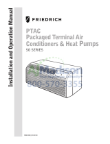
30°
45°
60°
30°
45°
60°
25ft
25ft
8ft
4ft
25ft
16ft
6ft
30°
30°
45°
60°
45°
60°
25ft
25ft
25ft
8ft
25ft
25ft
7.5ft
SIDE VIEW
TOP VIEW
Figure 11
Remote Control Operation
Remote Control - Refer to Figures 12 and 13 during operation description.
Getting Started - Install two (2) AAA batteries in the battery compartment
located on the back of the unit.
Operation - The remote control should be within 25 feet of the air
conditioner for operation. (Refer to Figure 11 for effectiveness). Press the
power button to turn the remote on. The remote will automatically power
off after 15 seconds if the buttons are not being pressed. The remote must
be on to control the unit.
POWER Button - Turns remote and unit on and off.
SYSTEM Button - Allows the user to sequentially select the
, HEAT , and FAN ONLY
following: AUTO - AUTO -, COOL
operations. When the button is pressed, the display indicates which mode
has been selected via a display message.Note that when the heating
automatically skip the HEAT mode.
FAN MODE Button - Selects between automatic ( AUTO FAN ) or CONTINUOUS
operation. In the AUTO FAN mode, the fan only turns on and off when the
compressor operates or the heat function is enabled.
NOTE: AUTO FAN is not available in the FAN ONLY Mode, the display
indicates CONTINUOUS . In the CONTINUOUS mode, fan speed is
determined by your selection on the FAN
SPEED button.
FAN SPEED Button - Used to sequentially select new fan speed, plus
AUTO operation. When the FAN
SPEED button is pressed, the fan speed icon
(triangle) changes to indicate the new speed level. Fan speed automatically
varies depending on the set temperature on the control panel and the actual
room temperature. For example if there is a big difference between your
set temperature and the actual room temperature, the system fan speed
increases to HIGH. It remains at this speed until the room temperature
matches the set temperature.
SCHEDULE Button – The SCHEDULE button turns the schedule function
on and off. Press the Schedule button once to turn on the Schedule
(Residential, Commercial, Timer, or Customized) that has already been
selected on your unit. Pressing the SCHEDULE button a second time turns
the schedule function off.
UP and DOWN Arrows - Pressing either the (UP) or (DOWN)
button changes the desired room temperature. The factory preset lower
and upper limits are 60°F (16°C) and 99°F (37°C). These buttons are also
used to navigate between function options when using the User Menu or
Maintenance Mode.
Remote Effectiveness
Hand Held Remote - Has an operating range of up to 25 ft. The infrared
remote control signal must have a clear path to transmit the command to
the air conditioning unit. The remote signal has some ability to "bounce"
off of walls and furniture similar to a television remote control. The diagram
below shows the typical operating range of the control in a standard room
with 8 ft high ceilings.
function is not available, the system will
/