© LINDY Group - SECOND EDITION (February 2023)
SDVoE Controller
User Manual English
No. 38364
lindy.com

User Manual English
Safety Instructions
! WARNING !
Please read the following safety information carefully and always keep this document with
the product.
Failure to follow these precautions can result in serious injuries or death from electric
shock, fire or damage to the product.
Touching the internal components or a damaged cable may cause electric shock, which
may result in death.
This device is a switching type power supply and can work with supply voltages in the range 100 - 240
VAC For worldwide usability four different AC adapters are enclosed: Euro type, UK type, US/Japan type
and Australia/New Zealand type. Use the appropriate AC adapter as shown in the picture and ensure it
is firmly secured in place and does not detach by pulling before installing into a power socket.
To reduce risk of fire, electric shocks or damage:
Do not open the product nor its power supply. There are no user serviceable parts inside.
Only qualified servicing personnel may carry out any repairs or maintenance.
Never use damaged cables.
Do not expose the product to water or places of moisture.
Do not use this product outdoors it is intended for indoor use only.
Do not place the product near direct heat sources. Always place it in a well-ventilated place.
Do not place heavy items on the product or the cables.
Please ensure any adapters are firmly secured and locked in place before inserting into a wall socket
Instructions for Use of Power Supply
To connect the adapter
Slide the desired plug adapter into the power supply until it locks
into place.
To remove the adapter
Press the push button latch.
While pressed, remove the adapter.

User Manual English
Introduction
Thank you for purchasing the SDVoE Controller. This product has been designed to provide trouble free,
reliable operation. It benefits from both a LINDY 2-year warranty and free lifetime technical support. To
ensure correct use, please read this manual carefully and retain it for future reference.
SDVoE is a globally recognised standard for high quality distribution of AV content with other features,
including control, matrix, video wall and multi view over longer distances via 10G Network with no
compressions and latency.
This Controller can be used to manage the Lindy SDVoE Transceiver 38365 that features HDMI, USB, IR,
RS-232 and Audio signals to distribute all the signals through a 10G managed network switch and to set
up many configurations and layouts. It supports dual network ports, one for network control and one for
multicast video distribution.
It provides control via Web GUI, TCP, RS-232, IR & GPIO.
SDVoE Alliance® is a registered trademark and SDVoE™ and SDVoE API™ are trademarks of the SDVoE
Alliance.
Package Contents
SDVoE Controller
IR Emitter Cable, 1.5m
IR Receiver Cable, 1.5m
2 x Mounting Ears & 4 x Screws
2 x 3-Pin Terminal Block
6-Pin Terminal Block
12VDC 1A Multi-country Power Supply (UK, EU, US & AUS), Screw Type DC Jack: 5.5/2.1mm
Lindy Manual
Features
Supports video, audio, RS-232, IR, KVM control and management of the distributed system
Maximum point-to-point Distance: 100m (328.08ft)
PoE (Power over Ethernet) support on Video LAN port
Built-in Web GUI control interface, supporting Drag & Drop operations and image preview
Dual network ports to isolate Controls and Multicast networks
Support LAN/RS-232 port control and third-party central control (API commands available on request)
Support IR Control (20 – 60KHz) on IR IN 3.5mm port (12V)
4 channel GPIO control ports (5V/12V optional level)
HTTPS, SSH, SFTP security compatible
Screw Type DC Jack for a secure power connection
Specification
Transmission distance: 100m
Network Video Bandwidth: 1G
PoE Standard: 802.3at
Operating Temperature: 0°C - 40°C (32°F - 104°F)
Storage Temperature: -20°C - 60°C (-4°F - 140°F)
Relative Humidity: 20 - 90% RH (Non-condensing)
Metal Housing
Colour: Black
Power Requirements: AC100-240V 50/60Hz
Power Consumption: 8.4W

User Manual English
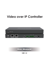
Installation
Front
1. RESET Button: Press and hold this button for 10 seconds when the unit is powered-on until the
STATUS LED starts flashing to restore the default settings.
2. POWER LED: Indicates power.
3. STATUS LED: This will flash yellow/green every second until the unit boots up completely and control
LAN is ready, then it will stay on.
4. UPDATE: Firmware update port (do not connect it while the unit is working).
Rear
1. DC 12V: Connect the 12VDC 1A PSU to an AC wall outlet and securely connector to the unit.
2. VIDEO LAN (PoE): Connect to the same Network Switch where all SDVoE Transceivers are connected
using a single RJ-45 Cat.6 or above cable. The unit can be powered via PoE if the connected Switch
has this feature.
3. CONTROL LAN: TCP/IP control network port.
4. RS-232: Connect one or two PC, Serial Controller or Serial device via two phoenix block 3-way
connection for the pass-through transmission of RS-232 commands.
5. 6-Pin Phoenix Connector: 4 channel I/O level outputs, 1 channel ground, 1 channel power output (up
to 12V 0.5A)
6. IO LEVEL: DIP Switch to control I/O level output and Voltage out; switch to left for 5V I/O level out,
switch to right for 12V I/O level out.
7. IR IN: Connect the supplied IR Receiver cable for 12V IR signal reception.
8. IR OUT: IR signal output port (reserved for future use).
Please Note:
- As default the IP mode of the CONTROL LAN port is DHCP, the PC connected needs to be set to
“Obtain an IP address automatically” mode and an optional DHCP server (for example a network
router) is recommended in the system.
- If there is no DHCP server in the system, 192.168.0.225 will be used as the IP address of the
CONTROL LAN port. Set the IP address of the PC in the same network segment (for example
192.168.0.88).

User Manual English
Operation
Web GUI
This Controller can be managed via the built-in Web GUI.
Please follow the below steps:
Input the Controller’s default IP address (192.168.0.225) or the URL (http://controller.local) into the Web
browser address bar on the PC to enter the Web GUI login interface:
Select the default username (admin) and password (1234) on the above login interface. Then, click on
Log In to enter the Web GUI interface. For the first time, you need to setup the project, as shown in the
following picture:
Click on Close button to load an existing project in the web page directly or click on Next button to go to
the next step.

User Manual English
On this interface, you need to set the IP mode of Video LAN.
Automatically managed by Controller Box
Click on Next button and wait for the completion to enter the interface as shown below:
Select Automatically add Encoders and Decoders to project and click on Scan button to enter the
Project page. All the connected devices will be listed in the Current Devices list.
Then click on Stop Scan & Auto Assign to stop the search.
Preview Page
On this page is possible to see the preview of the Encoder/Decoder by clicking on the dropdown lists.

User Manual English
Matrix Control Page
Encoders: Display all the connected Encoders. The text in the figure is the name of the device.
Decoders: Display all the connected Decoders. The text on the first line is the name of the Decoder and
the text on the second line refers to the Encoder where the signal resource comes from.
If an Encoder shows “No Signal”, it means that the Encoder cannot be dragged. If there is an image on
an Encoder, it means that the Encoder can be dragged. As shown in the figure above, if an Encoder is
dragged to the place where the red arrow points to, all Decoders will share the same signal resource
from this Encoder; if an Encoder is dragged to the place where the blue arrow points to, only the
indicated Decoder can receive signals from this Encoder.
Project Page
Current Devices: Devices that have been added to the current project.
Unassigned Devices: Devices not added to the current project.
Click on Display ID to display the ID or PATTERN of the Decoders.
Click on Save Project to save the project file (config_file.json) in order to use the saved project next time
without scanning devices again.
Click on Load Project to load the existing project directly.
Click on Clear Project to clear the current project, then is needed to setup the project again.
Click on Scan Once to search devices that do not appear in the current project.
Click on Start Scan & Auto Assign to search new devices automatically and add them to the current
project.

User Manual English
Encoders Page
Click on Refresh to refresh the data of the current Encoders.
ID: Shows the ID of the current device* (Note: ID cannot be duplicated).
Name: Shows the name of the current device.
MAC Address: Shows the MAC Address of the current device.
IP Address: Shows the IP Address of the current device.
Firmware: Shows the Firmware version of the current device.
Status: Shows the status (Online or Offline) of the current device.
EDID: Shows the EDID of the current device.
Click on the drop-down list to set the current Encoder’s EDID.
L/R Out: Shows the audio selection of the current device.
Click on the drop-down list to set the current Encoder’s audio output.
CEC Command: Shows the CEC Command of the current device.
Click on Command to set the CEC command for the Encoder.
*Click on the icon on the left of ID numbers to check the detailed information about the current Encoder
and setup it as required, as shown below:

User Manual English
Decoders Page
Click on Refresh to refresh the data of the current Decoders.
ID: Shows the ID of the current device* (Note: ID cannot be duplicated).
Name: Shows the name of the current device.
MAC Address: Shows the MAC Address of the current device.
IP Address: Shows the IP Address of the current device.
Firmware: Shows the Firmware version of the current device.
Status: Shows the status (Online or Offline) of the current device.
Source: Shows the signal source (Encoder) of the current device.
Click on the drop-down list of Source to select the current Decoder’s signal source.
Display Mode: Shows the display mode of the current device.
Click on the drop-down list of Display Mode to select the current Decoder’s display mode.
Scaler Resolution: Shows the resolution of the current device.
Click on the drop-down list of Scaler Resolution to select the current Decoder’s resolution.
Function: Shows the mode (Matrix / Video Wall / Multiview) of the current device.
Click on the drop-down list of Function to select the current Decoder’s mode.
CEC Command: Shows the CEC Command of the current device.
Click on Command to set the CEC command for the Decoder.

User Manual English
*Click on the icon on the left of ID numbers to check the detailed information about the current Decoder
and setup it as required, as shown in below:
Locked Signal Routing Page
On this page is possible to independently route the video and audio signals between Encoder & Decoder
devices. The IR/Serial/USB signals can be set up as required, by default are setted as N/A (Not Active),
select Follow to activate the required signals. Please click on Locked Routing Help for details.
Video Wall Management Page

User Manual English
On this page is possible to create and configure video wall applications. Click on Create, the following
pop-up window will be shown:
Set the Video Wall ID, Name, Horizontal and Vertical panel numbers. Then click on Create.
Note: Up to 9 video walls can be created.
Select the video wall that you want to configure on the Video Wall List, then click on Assign Decoder
to enter the Decoder assignment page.
Click on each screen to select the corresponding Decoder device, then click on Apply.
Note: A Decoder can only be assigned to one video wall.
Click on Class Configuration to enter the class configuration page, then click each screen to select the
corresponding Class as required (the same class name will form a video wall, you can create a regular
or irregular video wall). Then click on Apply.

User Manual English
Note: Up to seven configurations can be set up for different application scenarios.
After the configuration is completed, is possible to check it on the Video Wall Control page to see the
preview, as shown in the below example:
Here is possible to select different video walls and configurations saved in advance by clicking on the
drop-down boxes under Video Wall Selection and Configuration Selection. It’s also possible to drag
the Encoders directly on the top of the page to the video wall to change the signal sources.
To delete a video wall, just select the video wall on the Video Wall List, then click on Remove. A prompt
window will pop up and it can be deleted after clicking on Yes.

User Manual English
Notes:
- Each Decoder can be set into a part of a video wall array. Each system can contain multiple video walls
with different sizes. Each video wall can be assigned to different screens and different layouts with a
range from 1x2 up to 9x9.
- The controller creates and manages the video wall configurations and provides a simplified control
interface and API commands to third party control system.
Multiview Management Page
On this page is possible to create and configure Multiview options as required. Please follow the below
steps:
Click the drop-down list of Decoders to select the Decoder device as shown in the above figure. Then
click to select the desired Multiview Layout, which will be displayed in the lower right corner.
Drag Encoders from the Encoder List to the Multiview Layout respectively, then click on Apply.

User Manual English
After the configuration is completed, is possible to check it on the Multiview Control page to see the
preview, as shown in the below example:
Here is possible to select different Decoders and configurations saved in advance by clicking the drop-
down box under Receiver Selection and Configuration Selection.
To delete one Multiview configuration click on Reset, to delete all Multiview configurations click on Reset
All; a prompt window will pop up and it can be deleted after clicking on Yes.
Users Page
Here is possible to add new user accounts.

User Manual English
Controller Settings Page
General Settings: Shows the basic settings of the Controller.
Control Network: Shows the network port configuration of the Controller connected to the Switch.
Video Network: Shows the network port configuration of the Controller connected to the video source
devices.
Is possible to Update the settings or Reset Controller.
Firmware Update Page
Here is possible to update separately the firmware of any Encoder/Decoder by clicking the
corresponding Update button on the right or update all the firmware simultaneously by clicking the
corresponding Update All button. Is also possible to Update SS Firmware (Second Stream chip) and
Update NXP Firmware.

User Manual English
Password Update Page
Here is possible to change the password. Please note that after changing, it will skip to the Web browser
home page or the Web GUI login interface automatically. Then log in the Web GUI again with the new
password.
Log Out Page
Click on Log Out on the left, the Web GUI will exit and skip to the login interface automatically.
Infrared Pinout

User Manual English
Network Switch
The network Switch used to set up the system must support the below features:
• Layer 3/managed
• Bandwidth 10 Gigabit
• Support IGMP version 2, snooping enabled
• Filter/Drop unregistered multicast traffic
• Disable unregistered multicast flooding
• Enable fast leave support
Lindy tested this SDVOE Extender with a Netgear XSM4316S Switch, the following Netgear Switches are
recommended and optimized for SDVOE AV over IP applications:
XSM4216F-100NAS M4250-16XF MANAGED SWITCH
XSM4316PA-100NES M4300-16X POE+ APS299W
XSM4316PB-100NES M4300-16X POE+ APS600W
XSM4316S-100NES M4300-8X8F MANAGED SWITCH
XSM4324CS-100NES M4300-24X MANAGED SWITCH
XSM4324FS-100NES M4300-24XF MANAGED SWITCH
XSM4324S-100NES M4300-12X12F MANAGED SWITCH
XSM4348CS-100NES
M4300-48X MANAGED SWITCH
XSM4348FS-100NES
M4300-48XF MANAGED SWITCH
XSM4348S-100NES
M4300-24X24F MANAGED SWITCH
XSM4396K0-10000S
M4300-96X NO PORT CARD / NO PSU
XSM4396K1-100NES
M4300-96X 48XSFP+ APS600W BNDL

Recycling Information
WEEE (Waste of Electrical and Electronic Equipment), Recycling of Electronic Products
Europe, United Kingdom
In 2006 the European Union introduced regulations (WEEE) for the collection and recycling of all
waste electrical and electronic equipment. It is no longer allowable to simply throw away electrical and
electronic equipment. Instead, these products must enter the recycling process. Each individual EU
member state, as well as the UK, has implemented the WEEE regulations into national law in slightly
different ways. Please follow your national law when you want to dispose of any electrical or electronic
products. More details can be obtained from your national WEEE recycling agency.
Germany / Deutschland Elektro- und Elektronikgeräte
Informationen für private Haushalte sowie gewerbliche Endverbraucher
Hersteller-Informationen gemäß § 18 Abs. 4 ElektroG (Deutschland)
Das Elektro- und Elektronikgerätegesetz (ElektroG) enthält eine Vielzahl von Anforderungen an den
Umgang mit Elektro- und Elektronikgeräten. Die wichtigsten sind hier zusammengestellt.
1. Bedeutung des Symbols „durchgestrichene Mülltonne“
Das auf Elektro- und Elektronikgeräten regelmäßig abgebildete Symbol einer durchgestrichenen
Mülltonne weist darauf hin, dass das jeweilige Gerät am Ende seiner Lebensdauer getrennt vom
unsortierten Siedlungsabfall zu erfassen ist.
2. Getrennte Erfassung von Altgeräten
Elektro- und Elektronikgeräte, die zu Abfall geworden sind, werden als Altgeräte bezeichnet. Besitzer von
Altgeräten haben diese einer vom unsortierten Siedlungsabfall getrennten Erfassung zuzuführen.
Altgeräte gehören insbesondere nicht in den Hausmüll, sondern in spezielle Sammel- und
Rückgabesysteme.
3. Batterien und Akkus sowie Lampen
Besitzer von Altgeräten haben Altbatterien und Altakkumulatoren, die nicht vom Altgerät umschlossen
sind, sowie Lampen, die zerstörungsfrei aus dem Altgerät entnommen werden können, im Regelfall vor
der Abgabe an einer Erfassungsstelle vom Altgerät zu trennen. Dies gilt nicht, soweit Altgeräte einer
Vorbereitung zur Wiederverwendung unter Beteiligung eines öffentlich-rechtlichen Entsorgungsträgers
zugeführt werden.
4. Möglichkeiten der Rückgabe von Altgeräten
Besitzer von Altgeräten aus privaten Haushalten können diese bei den Sammelstellen der öffentlich-
rechtlichen Entsorgungsträger oder bei den von Herstellern oder Vertreibern im Sinne des ElektroG
eingerichteten Rücknahmestellen unentgeltlich abgeben.
Rücknahmepflichtig sind Geschäfte mit einer Verkaufsfläche von mindestens 400 m² für Elektro- und
Elektronikgeräte sowie diejenigen Lebensmittelgeschäfte mit einer Gesamtverkaufsfläche von mindestens
800 m², die mehrmals pro Jahr oder dauerhaft Elektro- und Elektronikgeräte anbieten und auf dem Markt
bereitstellen. Dies gilt auch bei Vertrieb unter Verwendung von Fernkommunikationsmitteln, wenn die
Lager- und Versandflächen für Elektro- und Elektronikgeräte mindestens 400 m² betragen oder die
gesamten Lager- und Versandflächen mindestens 800m² betragen. Vertreiber haben die Rücknahme
grundsätzlich durch geeignete Rückgabemöglichkeiten in zumutbarer Entfernung zum jeweiligen
Endnutzer zu gewährleisten.
Die Möglichkeit der unentgeltlichen Rückgabe eines Altgerätes besteht bei rücknahmepflichtigen
Vertreibern unter anderem dann, wenn ein neues gleichartiges Gerät, das im Wesentlichen die gleichen
Funktionen erfüllt, an einen Endnutzer abgegeben wird. Wenn ein neues Gerät an einen privaten Haushalt
ausgeliefert wird, kann das gleichartige Altgerät auch dort zur unentgeltlichen Abholung übergeben
werden; dies gilt bei einem Vertrieb unter Verwendung von Fernkommunikationsmitteln für Geräte der
Kategorien 1, 2 oder 4 gemäß § 2 Abs. 1 ElektroG, nämlich „Wärmeüberträger“, „Bildschirmgeräte“ oder
„Großgeräte“ (letztere mit mindestens einer äußeren Abmessung über 50 Zentimeter). Zu einer
entsprechenden Rückgabe-Absicht werden Endnutzer beim Abschluss eines Kaufvertrages befragt.
Außerdem besteht die Möglichkeit der unentgeltlichen Rückgabe bei Sammelstellen der Vertreiber
unabhängig vom Kauf eines neuen Gerätes für solche Altgeräte, die in keiner äußeren Abmessung größer
als 25 Zentimeter sind, und zwar beschränkt auf drei Altgeräte pro Geräteart.

Recycling Information
5. Datenschutz-Hinweis
Altgeräte enthalten häufig sensible personenbezogene Daten. Dies gilt insbesondere für Geräte der
Informations- und Telekommunikationstechnik wie Computer und Smartphones. Bitte beachten Sie in
Ihrem eigenen Interesse, dass für die Löschung der Daten auf den zu entsorgenden Altgeräten jeder
Endnutzer selbst verantwortlich ist.
France
En 2006, l'union Européenne a introduit la nouvelle réglementation (DEEE) pour le recyclage de tout
équipement électrique et électronique. Chaque Etat membre de l’Union Européenne a mis en application
la nouvelle réglementation DEEE de manières légèrement différentes. Veuillez suivre le décret
d’application correspondant à l’élimination des déchets électriques ou électroniques de votre pays.
Italy
Nel 2006 l’unione europea ha introdotto regolamentazioni (WEEE) per la raccolta e il riciclo di apparecchi
elettrici ed elettronici. Non è più consentito semplicemente gettare queste apparecchiature, devono essere
riciclate. Ogni stato membro dell’EU ha tramutato le direttive WEEE in leggi statali in varie misure. Fare
riferimento alle leggi del proprio Stato quando si dispone di un apparecchio elettrico o elettronico. Per
ulteriori dettagli fare riferimento alla direttiva WEEE sul riciclaggio del proprio Stato.
España
En 2006, la Unión Europea introdujo regulaciones (WEEE) para la recolección y reciclaje de todos los
residuos de aparatos eléctricos y electrónicos. Ya no está permitido simplemente tirar los equipos
eléctricos y electrónicos. En cambio, estos productos deben entrar en el proceso de reciclaje. Cada estado
miembro de la UE ha implementado las regulaciones de WEEE en la legislación nacional de manera
ligeramente diferente. Por favor, siga su legislación nacional cuando desee deshacerse de cualquier
producto eléctrico o electrónico. Se pueden obtener más detalles en su agencia nacional de reciclaje de
WEEE.

CE/FCC Statement
CE Certification
LINDY declares that this equipment complies with relevant European CE requirements.
CE Konformitätserklärung
LINDY erklärt, dass dieses Equipment den europäischen CE-Anforderungen entspricht
UKCA Certification
LINDY declares that this equipment complies with relevant UKCA requirements.
FCC Certification
This equipment has been tested and found to comply with the limits for a Class B digital device, pursuant
to part 15 of the FCC Rules. These limits are designed to provide reasonable protection against harmful
interference in a residential installation.
You are cautioned that changes or modification not expressly approved by the party responsible for
compliance could void your authority to operate the equipment.
This device complies with part 15 of the FCC Rules.
Operation is subject to the following two conditions:
1. This device may not cause harmful interference, and
2. This device must accept any interference received, including interference that may cause undesired
operation.
The enclosed power supply has passed Safety test requirements, conforming to the US American versions
of the international Standard IEC 60950-1 or 60065 or 62368-1.
LINDY Herstellergarantie – Hinweis für Kunden in Deutschland
LINDY gewährt für dieses Produkt über die gesetzliche Regelung in Deutschland hinaus eine zweijährige
Herstellergarantie ab Kaufdatum. Die detaillierten Bedingungen dieser Garantie finden Sie auf der LINDY
Website aufgelistet bei den AGBs.
Hersteller / Manufacturer (EU): Manufacturer (UK):
LINDY-Elektronik GmbH LINDY Electronics Ltd
Markircher Str. 20 Sadler Forster Way
68229 Mannheim Stockton-on-Tees, TS17 9JY
Germany England
Email: [email protected], T: +49 (0)621 470050 [email protected].uk, T: +44 (0)1642 754000
No. 38364
2nd Edition, February 2023
lindy.com
Tested to comply with
FCC
standards.
For home and office use.
/