Waterstage Air to Water Heat Pump Operating instructions
- Category
- Heat pumps
- Type
- Operating instructions
This manual is also suitable for

Operation manual
intended for professionals
and end users.
To be saved for
future consultation
Document n° 1534-1 ~ 13/06/2012
Fujitsu General (Euro) GmbH
Werftstrasse 20
40549 Düsseldorf - Germany
Subject to modications without notice.
Non contractual document.
FR NL DE EN IT
ES PT
Split system
Air to Water Heat Pump

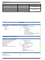
Contents
Instructions to be read before using the equipment . . . . . . . . . . . . . . 3
Safety instructions . . . . . . . . . . . . . . . . . . . 3
Start-up . . . . . . . . . . . . . . . . . . . . . 3
Use . . . . . . . . . . . . . . . . . . . . . . . 3
Maintenance . . . . . . . . . . . . . . . . . . 3
Precautions and warnings regarding
your installation. . . . . . . . . . . . . . . . . . . . . 4
The outdoor unit . . . . . . . . . . . . . . . . 4
The hydraulic unit . . . . . . . . . . . . . . . . 4
Control system . . . . . . . . . . . . . . . . . 4
The radiators . . . . . . . . . . . . . . . . . . 4
Floor-heating systems . . . . . . . . . . . . . 4
Fan convectors with integrated control system . . 4
Domestic hot water (DHW) . . . . . . . . . . . 4
Maintenance . . . . . . . . . . . . . . . . . . . . . . . . . . . . . . . . . . 18
Overall view of the installation . . . . . . . . . . . . . . . . . . . . . . . . . 5
Operation of the installation . . . . . . . . . . . . . . . . . . . . . . . . . . . 6
User interface, Remote control (option)
and Room thermostat (option) . . . . . . . . . . . . . 6
Description of the display . . . . . . . . . . . . . . . 8
Appliance start up . . . . . . . . . . . . . . . . . . . 9
Quick start-up . . . . . . . . . . . . . . . . . . . . . 9
Setting the time . . . . . . . . . . . . . . . . . . . 10
Structure of the "End user" control menu . . . . . . 11
Parametering the setting . . . . . . . . . . . . . . 12
General . . . . . . . . . . . . . . . . . . . . 12
Setting parameters . . . . . . . . . . . . . . 12
List of "End user" settings . . . . . . . . . . 12
Information display . . . . . . . . . . . . . . . . . 16
Details . . . . . . . . . . . . . . . . . . . . . . . . 16
Operation of the DHW system . . . . . . . . . . . . 17
Selecting cooling mode . . . . . . . . . . . . . . . 17
Pilot-wire . . . . . . . . . . . . . . . . . . . . . . . 17
Telephone modem . . . . . . . . . . . . . . . . . . 17
Conguring remote control (option) . . . . . . . . . 17
Regular checks . . . . . . . . . . . . . . . . . . . 18
Checking the outdoor unit . . . . . . . . . . . . . . 18
Operation manual "1534 - EN"
Air to Water Heat Pump
- 2 -
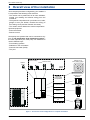
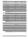
Packing list
Heat Pump Outdoor Unit Hydraulic Unit
Model Reference Reference
Waterstage High Power 11 single phase WO*G112LCT WS*G140DC6
Waterstage High Power 14 single phase WO*G140LCT
Waterstage High Power 11 3-phase WO*K112LCT
WS*K160DC9Waterstage High Power 14 3-phase WO*K140LCT
Waterstage High Power 16 3-phase WO*K160LCT

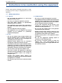
1 Instructions to be read before using the equipment
Please comply with the following instructions in order
to avoid any risk of injury or inappropriate use of the
appliance.
1.1 Safety instructions
1.1.1 Start-up
"Do not switch the appliance on until every
llings have been done.
"Do not try to install this appliance yourself.
"This heat pump requires an appropriately
qualied person to install it.
"The installation must always be connected to
the Earth and tted with a protective circuit
breaker.
"Do not modify the electricity supply.
"The appliances are not reproof and should
therefore not be installed in a potentially
explosive atmosphere.
1.1.2 Use
"Do not let children insert foreign bodies into
the fan protection grill or climb on top of the
outdoor unit. The ns on the air exchanger are
extremely ne and cause cuts.
"Nothing should obstruct the air circulation
through the evaporator and from the fan.
"The outdoor unit must only be installed outdoor
(outdoors). If a shelter is required, it must have
broad openings on the 4 walls and observe the
installation clearances (see with your installer).
"Do not climb on the top of the outdoor unit.
"The room in which the appliance is operating
must be correctly ventilated in order to prevent
any loss of oxygen if there is an escape of
refrigerant gas.
"Consult your Installer before making any
changes or modications to the premises where
the appliance is installed.
"Do not place any heat source under the remote
control.
1.1.3 Maintenance
"Do not try to repair this appliance yourself.
"This appliance does not contain any components
capable of being repaired by the user himself.
Removing one or other of the covers can expose
you to dangerous electrical voltages.
"In any case, switching off the current is not
sufcient to protect you from any external
electrical shocks (capacitors).
"Do not open the outdoor unit or the hydraulic
unit while they are operating.
"Switch off the power supply if there are any
abnormal noises, smells or smoke coming from
the appliance and contact your installer.
"Switch off the power to the appliance before
you clean it.
"Do not use aggressive cleaning liquid or
solvents to clean the body work.
"Do not use a pressure washer to clean the
outdoor unit. This could damage the air
exchanger and the water might penetrate into
the electrical circuits.
Operation manual "1534 - EN" - 3 -
Air to Water Heat Pump

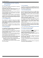
1.2 Precautions and warnings regarding
your installation.
1.2.1 The outdoor unit
The outdoor unit contains the equipment for capturing
energy from the ambient air.
Your installer has placed this unit in a location that
enables it to operate in an optimum manner.
Nothing should obstruct the air circulation through the
evaporator and from the fan.
The control system for your heating system is designed
in ow temperature for the water based on the outdoor
temperature (water control).
In cold periods, this water freezes in contact with the
exchanger and is drained away by regular defrosting
cycles. The control system automatically controls the
defrosting cycle, whose operation can lead to the quite
normal emission of steam.
1.2.2 The hydraulic unit
The hydraulic unit contains the heat pump complete
control system, in charge of controlling the heating
comfort level and the production of domestic hot water
(if the installation is tted with a DHW tank with electrical
back-up heating).
The heat pump is equipped with an electric back-up
system, which is designed to provide additional heat
during the coldest periods.
1.2.3 Control system
Your installer has carefully adjusted your installation. Do
not modify setting parameters without his agreement. If
in doubt, do not hesitate to contact him.
The control system for your heating system is designed
in ow temperature for the water based on the outdoor
temperature (water control).
The installation of a room thermostat (option) allows to
improve operation of the regulation (the inuence of the
room temperature is taken into account).
The frost protection works in all modes of operation and
has priority over other functions (provided that the heat
pump's electrical power supply is not interrupted).
"Warning ! In winter, in case of power failure, the
frost protection is no longer assured.
The water in the tank of the hydraulic module can freeze
and cause damage.
1.2.4 The radiators
To ensure the function of the regulation with room
inuence, it's necessary that the room in which the room
thermostat is installed has no thermostatic valve or that
they must be completely open.
1.2.5 Floor-heating systems
New oor-heating systems require to be initially heated
slowly to avoid any problems with cracking. Check
with your installer that this initial heating procedure
has indeed been performed before using your heating
system freely.
The great stability in a regulation system for oor-heating
systems avoids sharp differences in temperature.
However, this stability involves a reaction time of the
order of several hours, (approx 6 hours).
Any changes to the setting must be made slowly, leaving
the installation time to react. Adjusting the system to
exaggerated setting or in an untimely manner always
results in signicant temperature uctuations during
course of the day.
Similarly if your dwelling has a oor-heating system,
do not reduce the heating or switch it off if you will be
absent for a short period. The reheating period is always
quite long (approx 6 hours).
1.2.6 Fan convectors with integrated control system
Do not use a room sensor in the area.
1.2.7 Domestic hot water (DHW)
This function is designed as an option through the use
of a DHW tank with electrical back-up heating.
When the DHW production is required, the heat pump
adapts to this demand with higher priority.
No space heating is produced while the domestic hot
water is being prepared.
Domestic hot water (DHW) is produced by the heat
pump and then topped up, if necessary, by electrical
backup heating or the boiler.
To ensure a DHW setting over 45°C, the electrical back-
up heating or the boiler must be left on (Optional boiler
connection kit).
The electrical back-up heating enables anti-legionella
cycles to be conducted efciently.
Operation manual "1534 - EN"
Air to Water Heat Pump
- 4 -

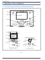
2 Overall view of the installation
Your heat pump has been congured by your installer. It
is composed of the following main elements:
- The outdoor unit is positioned, as its name indicates,
outside your dwelling and extracts energy from the
outside air.
- The hydraulic unit positioned in your boiler room, cellar,
garage or even your kitchen, transfers the energy to
the heating circuit (and the domestic hot water).
- The outdoor sensor detects the outdoor temperature.
Optional equipment:
- Room thermostat.
- Remote control.
Heat pumps are systems that can be connected to any
form of low temperature heat distribution systems :
the heat captured by the heat pump can therefore be
used in different ways:
- Floor-heating systems.
- Radiators or fan coil heaters.
- Domestic hot water (DHW).
- The pool.
gure 1 - Overall view of the conguration of a complete installation
Outdoor
sensor
Room thermostat
(wired or radio) Remote control
(wired or radio) Heating circuit
Floor heating system
Heating circuit
Radiators
DHW tanks
with electrical back-up
Boiler
Options
depending
on the system
congurations
2nd circuit kit
Boiler connexion
kit
DHW kit
Hydraulic unit
Outdoor unit
Control
options
or/and
Operation manual "1534 - EN" - 5 -
Air to Water Heat Pump

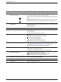
3 Operation of the installation
3.1 User interface, Remote control (option) and Room thermostat (option)
gure 2 -
°C
Auto
Auto
ESC OK
0 4 8 12 16 20 24
1
2
3
4
5
6
7
8
11
5
2
10
11
Remote control (option) Room thermostat (option)
1
2
3
4
5
6
7
8
9
User interface
Operation manual "1534 - EN"
Air to Water Heat Pump
- 6 -

Ref. Functions - Denitions
1 Selecting of the DHW operating mode
(Domestic hot water).
On
Off
- If the installation is tted with a DHW tank.
-On: Production of DHW according to the time program.
-Off: Preparing the domestic hot water for stopping with the anti-frost function
active.
-Manual start button: Hold down the DHW key for 3 seconds. Switch from
"reduced" to "comfort" until the next time the ECS timer switches over.
2 Digital display. - Operating control. Readout of the current temperature, of the heating mode
and of any faults .
- View the settings.
3 Exit "ESC". - Quit the menu.
4 Navigation and setting. - Selecting the menu.
- Setting parameters.
- Adjusting the ambient temperature setpoint.
5 Selecting the heating mode. -
Auto
Heating operating according to the heating program
(Summer/winter mode switchover is automatic).
- Constant comfort temperature.
- Constant reduced temperature.
- Stand-by mode with anti-frost protection
(Provided that the heat pump's electrical power supply is not interrupted).
6 Information display. - Various data (see page 16).
- Reading error codes (see Installation and operating manual).
- Information concerning maintenance, special mode.
7 Conrm "OK". - Input into the selected menu.
- Conrmation of the parameter settings.
- Conrmation of the adjustment to the comfort temp. setting.
8 Selecting cooling mode. - If the installation is tted with the cooling kit:
- Cooling operating according to the heating program
(Summer/winter mode switchover is automatic).
9 RESET button
(Hold down the "RESET" key for 3 sec).
- Reinitialising the parameters and cancelling error messages.
Do not use during normal operation.
10 Control knob. - Adjusting the ambient temperature setpoint.
11 Presence key. - Comfort / Reduced switchover.
Operation manual "1534 - EN" - 7 -
Air to Water Heat Pump

gure 3 -
3.2 Description of the display
Symbols Denitions
- Heating mode active with reference
to the heating circuit.
- Heating in comfort mode.
- Heating in reduced mode.
- Heating in "standby" mode
(freeze protection).
- Cooling mode active.
- Holiday mode activated.
- Process in progress.
- Compressor operation.
- Burner operation.
- Default message.
- Service / Special operation.
INFO - Information level activated.
PROG - Program activated.
ECO - ECO mode activated
(Heating temporarily stopped).
temperature ambiante
- Hour /
Parameter number /
Setpoint value.
temperature ambiante
- Room temperature /
Setpoint value.
temperature ambiante
- Setpoint information /
Parameter Information.
Xxxxxxxxxxxxxxxxxxxxxxxxxxx
Xxxxxxxxxxxxxxxxxxxxxxxxxxx
Xxxxxxxxxxxxxxxxxxxxxxxxxxx
Operation manual "1534 - EN"
Air to Water Heat Pump
- 8 -

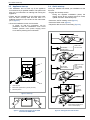
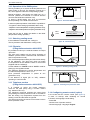
3.3 Appliance start up
• The installation and 1st start up of the appliance
must be done by a qualied installer. That person will
also give you instructions on starting and running the
appliance.
• Ensure that the installation is fully lled with water
and has been correctly bled and that there is a
sufcient pressure of 1,5 to 2 bars on the manometer
(ref. 2, gure 4).
• Close the installation's main circuit breaker.
In winter, so that the compressor can be
preheated, close the installation's main circuit
breaker (outdoor unit's power supply) some
hours before pressing the on/off button.
3.4 Quick start-up
Once your installer has started your installation for the
rst time:
• Engage the start/stop switch.
During the regulator initialisation phase, the
display shows all the symbols and then "Data,
update" and then "State heat pump".
• Select the "AUTO" heating mode (gure 5).
• Select the DHW mode (gure 5).
• Adjust the date and time if necessary (gure 6).
gure 4 - Start-up
1. User interface
2. Manometer (installation hydraulic pressure)
3. Start/stop switch
1
2
3
gure 5 - Selecting the heating mode AUTO
and Select the DHW mode gure 6 - Setting the time and the date
_______________
Press OK
Press OK
Press OK
Press heating mode key to
return to basic display
Select menu
hour and date
Select one of the
lines :
hour / minutes
or day / month
or years
Make all the
settings
Press OK to
conrm each
setting
Time and date
Operator section
Time and date
Hours / minutes
Time and date
Hours / minutes
Operation manual "1534 - EN" - 9 -
Air to Water Heat Pump

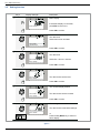
3.5 Setting the time
gure 7 -
04 8 12 16 20 24
AUTO
2
04 8 12 16 20 24
AUTO
3
04 8 12 16 20 24
AUTO
4
04 8 12 16 20 24
AUTO
1
5
04 8 12 16 20 24
AUTO
6
0 4 8 12 16 20 24
AUTO
Keys Display example Description
Basic display
If the basic display is not shown,
press ESC to return to it
Press OK to conrm.
Turn the knob
Select menu hour and date
Press OK to conrm.
Turn the knob
Select line 1 Hours / minutes
Press OK to conrm.
The hour display ashes
Turn the knob to set the time
Press OK to conrm.
The minutes display ashes
Turn the knob to set the minutes
Press OK to conrm.
The setting are recorded
Room temperature
Time and date
Operator section
Time and date
Hours / minutes
Time and date
Hours / minutes
Time and date
Hours / minutes
Time and date
Hours / minutes
Turn the knob to make other settings
or
Press heating Mode key to return to
basic display.
Operation manual "1534 - EN"
Air to Water Heat Pump
- 10 -

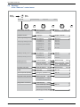
3.6 Structure
of the "End user" control menu
1
2
3
20
500
501
502
503
504
505
506
515
516
641
642
643
648
710
712
714
6711
7141
8410
8412
8413
8700
8701
8702
...
8900
65 °C
1610
1 ...24 h
0...60 min
28 °C
4 °C...
...
English, German...
Basic
display
Brief
press
End user Commissioning Engineer OEM
Time of day and date Hours / minutes
Day / Month
Year
Hours
Minutes
Operator section Language
Time prog heating circuit 1
Time prog heating circuit 2
Time program 4/DHW
Pre-selection
Pre-selection
1st phase on
1st phase off
1st phase on
1st phase off
2nd phase on
2nd phase off
3rd phase on
3rd phase off
Default values
Copy
Mon-Sun
Mon-Fri
Sat-Sun
Monday
Tuesday
…
Sunday
Holidays heating circuit 1
Holidays heating circuit 2 Operation level
Period 1
Period 2
...
Period 8
Heating circuit 1
Heating circuit 2
Comfort setpoint Reduced temp...
Reduced setpoint
Temp. frost protect... comfort
Frost protect. setpoint
reduced temp.
Domestic hot water Nominal setpoint
Reduced temp...
Fault Reset HP No, Yes
Service/special operation
Emergency operation
Off, On
Diagnostics heat generation
Return temp HP
Flow temp HP
Compressor modulation
Diagnostics consumers Outdside temp.
Reset outside temp min
Off, On
Reset outside temp max
Swimming pool temp.
gure 8 -
Operation manual "1534 - EN" - 11 -
Air to Water Heat Pump

3.7 Parametering the setting
3.7.1 General
Only the parameters accessible to levels:
End user
Are described in this document.
The parameters accessible at level:
Commissioning
Engineer
… are described in the document reserved for
these professional specialists. Do not make any
modications to these parameters without advice
from these professional specialists. Incorrect use
of any kind may result in serious malfunctioning.
3.7.2 Setting parameters
With the screen on basic display.
- Press OK.
Once in "End user" level.
- Scroll the menu list.
- Choose the desired menu.
- Scroll the function lines.
- Choose the desired line.
- Adjust the parameter.
- Check the setting by pressing OK.
- To return the menu, press ESC.
If no setting is made for 8 minutes, the screen returns
automatically to the basic display.
3.7.3 List of "End user" settings
Line Function Setting range
or display
Setting
increment
Basic
setting
Time of day and date
1 Hours / minutes 00:00... 23:59 1
2 Day / Month 01.01... 31.12 1
3 Year 1900... 2099 1
Operator section
20 Language English, Deutsch, Français,
Italiano, Nederlands,...
English
OK
Brief
press End user
OK OK OK
Tim and date Hours / minutes 1 Hours 1...24 h
User interface Day / Month 2 Minutes 0...60 min
CC1 time program Year 3
...
Operation manual "1534 - EN"
Air to Water Heat Pump
- 12 -

Line Function Setting range
or display
Setting
increment
Basic
setting
Time program heating, circuit 1
500 Pre-selection (Day / Week) Mon-Sun, Mon-Fri, Sat-Sun,
Monday, Tuesday, …
Mon-Sun
501 1st phase On (start) 00:00... --:-- 10 min 6:00
502 1st phase Off (end) 00:00... --:-- 10 min 22:00
503 2nd phase On (start) 00:00... --:-- 10 min --:--
504 2nd phase Off (end) 00:00... --:-- 10 min --:--
505 3rd phase On (start) 00:00... --:-- 10 min --:--
506 3rd phase Off (end) 00:00... --:-- 10 min --:--
515 Copy
516 Default values No, Yes No
Yes + OK: The default values memorised in the regulator replace and cancel the customised heating programs. Your
customised settings are therefore lost.
Time program heating, circuit 2
Only with the 2nd circuit kit option.
520 Pre-selection (Day / Week) Mon-Sun, Mon-Fri, Sat-Sun,
Monday, Tuesday, …
Mon-Sun
521 1st phase On (start) 00:00... --:-- 10 min 6:00
522 1st phase Off (end) 00:00... --:-- 10 min 22:00
523 2nd phase On (start) 00:00... --:-- 10 min --:--
524 2nd phase Off (end) 00:00... --:-- 10 min --:--
525 3rd phase On (start) 00:00... --:-- 10 min --:--
526 3rd phase Off (end) 00:00... --:-- 10 min --:--
535 Copy
536 Default values No, Yes No
Yes + OK: The default values memorised in the regulator replace and cancel the customised heating programs. Your
customised settings are therefore lost.
Time program 4 / DHW
If the installation is tted with the DHW kit (Only with the DHW kit option).
560 Pre-selection (Day / Week) Mon-Sun, Mon-Fri, Sat-Sun,
Monday, Tuesday, …
Mon-Sun
561 1st phase On (start) 00:00... --:-- 10 min 00:00
562 1st phase Off (end) 00:00... --:-- 10 min 05:00
563 2nd phase On (start) 00:00... --:-- 10 min 14:30
564 2nd phase Off (end) 00:00... --:-- 10 min 17:00
565 3rd phase On (start) 00:00... --:-- 10 min --:--
566 3rd phase Off (end) 00:00... --:-- 10 min --:--
575 Copy
576 Default values No, Yes No
Yes + OK: The default values memorised in the regulator replace and cancel the customised heating programs. Your
customised settings are therefore lost.
Operation manual "1534 - EN" - 13 -
Air to Water Heat Pump

Line Function Setting range
or display
Setting
increment
Basic
setting
Time program 5 / Cooling
If the installation is tted with the cooling kit (Only with the cooling kit option).
600 Pre-selection (Day / Week) Mon-Sun, Mon-Fri, Sat-Sun,
Monday, Tuesday, …
Mon-Sun
601 1st phase On (start) 00:00... --:-- 10 min 8:00
602 1st phase Off (end) 00:00... --:-- 10 min 20:00
603 2nd phase On (start) 00:00... --:-- 10 min --:--
604 2nd phase Off (end) 00:00... --:-- 10 min --:--
605 3rd phase On (start) 00:00... --:-- 10 min --:--
606 3rd phase Off (end) 00:00... --:-- 10 min --:--
615 Copy
616 Default values No, Yes No
Yes + OK: The default values memorised in the regulator replace and cancel the customised heating programs. Your
customised settings are therefore lost.
Holidays, heating circuit 1 (For the Holiday program is active, the heating mode should be on AUTO).
641 Preselection Period 1 to 8 Period 1
642 Period Start (Day / Month) 01.01... 31.12 1
643 Period End (Day / Month) 01.01... 31.12 1
648 Operating level Frost protection, Reduced Frost
protection
Holidays, heating circuit 2 (For the Holiday program is active, the heating mode should be on AUTO).
If the installation consists of 2 heating circuits (Only with the 2nd circuit kit option).
651 Preselection Period 1 to 8 Period 1
652 Period Start (Day / Month) 01.01... 31.12 1
653 Period End (Day / Month) 01.01... 31.12 1
658 Operating level Frost protection, Reduced Frost
protection
Heating, circuit 1
710 Comfort setpoint Reduced setpoint… 28 °C 0,5 °C 20 °C
712 Reduced setpoint Frost protection setpoint…
Comfort setpoint
0,5 °C 19 °C
714 Frost protection setpoint 4 °C… Reduced setpoint 0,5 °C 8 °C
Cooling circuit 1
If the installation is tted with the cooling kit (Only with the cooling kit option).
901 Operating mode Off, Automatic Off
902 Comfort cooling setpoint 17... 40 °C 0,5 °C 24 °C
907 Release 24h/day, Time program HC,
Time program 5 / Cooling
Time
program 5
If the installation is tted with a DHW tank, set the parameter 907 to "Time program 5 / Cooling"
(In order to activate cooling only during the day and leave the DHW system to operate during the night).
Heating, Circuit 2
Only with the 2nd circuit kit option (If the installation consists of 2 heating circuits).
1010 Comfort setpoint Reduced setpoint… 28 °C 0,5 °C 20 °C
1012 Reduced setpoint Frost protection setpoint…
Comfort setpoint
0,5 °C 19 °C
1014 Frost protection setpoint 4°C… Reduced setpoint 0,5 °C 8 °C
Operation manual "1534 - EN"
Air to Water Heat Pump
- 14 -

Line Function Setting range
or display
Setting
increment
Basic
setting
Domestic hot water
If the installation is tted with the DHW kit (Only with the DHW kit option).
1610 Nominal setpoint Reduced setpoint (line 1612)…
65 °C 155 °C
The backup electrical system is required to reach this level.
1612 Reduced setpoint 8 °C...
Nominal setpoint (line 1610)
140 °C
Swimming pool (Only with swimming pool kit option)
2056 Setpoint source heating 8... 35 °C 22 °C
Error
6711 Reset HP No, Yes No
Maintenance / special regime
7141 Emergency operation Off, On Off
Off: Heat pump functions normally (with boosters if necessary).
On: Heat pump uses the electric boost system or the boiler connection.
Use the “On” position only in Assist mode or Test mode: may result in high power bills.
Diagnostics heat generation
8410 Return temp HP 0... 140 °C
Setpoint (ow) HP
8412 Flow temp HP 0... 140 °C
Setpoint (ow) HP
8413 Compressor modulation 0... 100%
Diagnostics consumers
8700 Outside temperature -50... 50 °C --
8701 Outside temp min
Reset ? (no, yes)
-50... 50 °C --
8702 Outside temp max
Reset ? (no, yes)
-50... 50 °C --
8740 Room temperature 1 0... 50 °C --
Room setting 1 20 °C
8743 Flow temperature 1 0... 140 °C --
Flow temperature setpoint 1 --
8756 Cooling ow temperature 1 0... 140 °C --
Cooling ow temperature setpoint 1 --
8770 Room temperature 2 0... 50 °C --
Room setpoint 2 20 °C
8773 Flow temperature 2 0... 140 °C --
Flow temperature setpoint 2 --
8830 DHW (domestic hot water) temperature 0... 140 °C --
DHW temperature setpoint 50 °C
8900 Swimming pool temperature 0... 140 °C --
Swimming pool temperature setpoint 22 °C
Operation manual "1534 - EN" - 15 -
Air to Water Heat Pump

- Various data (see below).
Designation Line
Floor drying current setpoint . -
Current drying day. -
Terminated drying days. -
State heat pump. 8006
State supplementary source. 8022
State DHW. 8003
State swimming pool. 8011
State heating circuit 1. 8000
State heating circuit 2. 8001
State cooling circuit 1. 8004
Outdoor temperature. 8700
Room temperature 1. 8740
Room setpoint 1.
Flow temperature 1. 8743
Flow temperature setpoint1.
Room temperature 2. 8770
Room setpoint 2.
Flow temperature 2. 8773
Flow temperature setpoint 2.
DHW (domestic hot water) temperature. 8830
Heat pump return temperature. 8410
Setpoint (return) HP.
Heat pump ow temperature. 8412
Setpoint (ow) HP.
Swimming pool temperature. 8900
Swimming pool temperature setpoint.
Minimum remaining stop time for compressor 1. -
Minimum remaining running time for compressor 1. -
3.9 Details
If the electrical power supply has been cut off while
the heat pump is operating (electrical power failure or
unprogrammed pressing of the on/off switch on the
hydraulic unit) the display will show error 370 when
the appliance restarts. Do not be concerned, the
communication between the outdoor and hydraulic unit
will re-establish itself in a few moments.
3.8 Information display
Various data can be displayed by pressing the info
button.
Depending on the type of unit, conguration and
operating state, some of the info lines listed below may
not appear.
- Possible error messages: The display shows the "Bell"
symbo .
"Consult your heating technician.
- Service messages ; Special mode messages:
The display shows the “Key” symbol .
"Consult your heating technician.
Operation manual "1534 - EN"
Air to Water Heat Pump
- 16 -

3.10 Operation of the DHW system
The key enables you to switch the DHW (domestic hot
water) mode on and off. The selection is shown by a
bar, which appears under the corresponding symbol.
Manual activation: Hold down the DHW key for 3
seconds (Switch from "reduced" to "nominal" until the
next time the DHW timer switches over).
To ensure a DHW setting over 45°C, the electrical
back-up heating or the boiler must be left on.
In order to optimise operation of the DHW, it is possible to:
- Program the timer settings (parameters 560 to 576),
- Adjust the nominal temperature set point (parameter 1610),
- Adjust the reduced temperature set point (parameter 1612).
Press the info key to obtain the details on the DHW
(temperature setting operation).
3.11 Selecting cooling mode
If the installation is tted with the cooling kit.
The key activates and deactivates cooling mode.
3.12 Pilot-wire
(if Regulation extension kit AVS 55)
It's possible to order up to 15 electric heaters via output
"pilot wire".
The "pilot wire" handles only the hourly operation of
radiators (comfort mode / reduced mode commutation
and Frost protection mode).
The comfort temperature setting should be done directly
on the radiator(s). The "pilot wire" does not handle
the temperature of the radiators. Refer to the manual
supplied with the radiator(s).
Put the radiators on "PROG" mode or "AUTO" mode for
piloting by the regulation board.
The difference between the comfort temperature and
the reduced temperature is from 3,5 °C.
Frost protection temperature is preset at 8°C
(parameter 1014).
In the absence of signal (HP on "Off"), radiators
operating in comfort mode
3.13 Telephone modem
(if Regulation extension kit AVS 55)
It is possible to select the freeze protection
mode on the heat pump using a modem contact
(e.g. Siemens TEL 110).
The telephone command switches the current heat
pump settings to freeze protection mode. In accordance
with the setting, any temperature requests from the
heating circuits and the DHW are ignored.
The heat pump and/or the remote control must not be in
freeze protection mode.
gure 9 - Select the DHW mode
gure 10 - Information key
Brief
press
Details of any error
Operating values
...
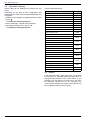
3.14 Conguring remote control (option)
In the event that the remote control (see gure 2),
is used, on start-up, after initialising for around
3 minutes, the language needs setting:
- Press OK.
- Choose menu "Operator section".
- Choose language "Language" English.
gure 11 - Selecting cooling mode
Operation manual "1534 - EN" - 17 -
Air to Water Heat Pump
gure 12 - Selecting Frost protection mode

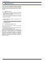
4 Maintenance
In order to insure your appliance operates correctly for
many years, the maintenance operations described
below are required at the start of each heating season.
Generally, these are performed as part of a service
contract.
4.1 Regular checks
- Periodically check the water pressure in the heating
circuit (Refer to the pressure recommended by the
installer - between 1 to 2 bar).
- If lling and re-pressurization are required, check what
type of uid has been used initially (If in any doubt,
contact your installer).
- If frequent rells are required it is essential that you
look for any leaks.
"The frequent water supply is at risk of scaling for
the Heat exchanger and degrades performance
and longevity of it.
4.2 Checking the outdoor unit
Dust off the heat exchanger if necessary, being careful
not to damage the ns.
Check that there is nothing obstructing the passage of air.
• Checking the refrigeration circuit
When the refrigerant charge is in excess of 2kg
(excellia 11 single phase, excellia 14 single phase,
excellia 11 3-phase, excellia 14 3-phase and
excellia 16 3-phase models) it is compulsory to have
an approved after sales service check the refrigeration
circuit every year (with a certicate of capacity for
the handling of refrigerants). Consult your heating
technician.
Operation manual "1534 - EN"
Air to Water Heat Pump
- 18 -
When the refrigerant charge is in excess of 2kg
(High Power 11 single phase, High Power 14 single phase,
High Power 11 3-phase, High Power 14 3-phase and
High Power 16 3-phase models) it is compulsory
to have an approved after sales service check the
refrigeration circuit every year (with a certicate of
capacity for the handling of refrigerants). Consult your
heating technician.

Operation manual "1534 - EN" - 19 -
Air to Water Heat Pump

Date of installation :
Contact of your heating technician or your after-sales service.
This appliance is marked with this symbol. This means that electrical and electronic products shall not be mixed with general household waste.
European Community countries(*), Norway, Iceland and Liechtenstein should have a dedicated collection system for these products.
Do not try to dismantle the system yourself as this could have harmful effects on your health and on the environment.
The dismantling and treatment of refrigerant, oil and other parts must be done by a qualied installer in accordance with relevant local and national regulations.
This appliance must be treated at a specialized treatment facility for re-use, recycling and other forms of recovery and shall not be disposed of in the municipal waste stream.
Please contact the installer or local authority for more information.
* subject to the national law of each member state
Subject to modications without notice. Non contractual document.
-
 1
1
-
 2
2
-
 3
3
-
 4
4
-
 5
5
-
 6
6
-
 7
7
-
 8
8
-
 9
9
-
 10
10
-
 11
11
-
 12
12
-
 13
13
-
 14
14
-
 15
15
-
 16
16
-
 17
17
-
 18
18
-
 19
19
-
 20
20


Waterstage Air to Water Heat Pump Operating instructions
- Category
- Heat pumps
- Type
- Operating instructions
- This manual is also suitable for
Ask a question and I''ll find the answer in the document
Finding information in a document is now easier with AI
Related papers

Other documents
-
Fujitsu WOYA080LFCA Comfort Operating instructions
-
-
-
-
-
Fujitsu WGYK170DJ9/WOYK170LJL Installation guide
-
-
-
Fujitsu WSHG160DJ6/WOHG160LJL Installation guide
-