Page is loading ...

3/4” thermostatic valve
Updated: 10-09-04
Products info: www.aquabrass.com INS-SCT3/ 4-2-E
INSTALLATION PROCEDURES
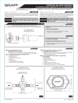
1 HOW TO USE THE ROUGH-IN CAP
#1010
ROUGH-IN
CAP
ATTENTION: MAKE SURE TO FLUSH THE HOT AND COLD WATER
SUPPLY LINES BEFORE BEGINNING THE INSTALLATION.
TILE
GYPROC
2X4
2X6
ROUGH-IN CAP
SUPPORT 3/4”
RECOMMENDED
The thermostatic valve # 1010 is protected by a plastic protective
covering. It can be used for different functions :
A. It can be used as a rough-in cap for setting the depth of the
valve in the wall. If you look closely at the rough-in cap, you will see
the Min and Max written on it. That means that the thickness of the
finished wall must be in between those two marks, so the valve can
take the minimum depth at 2 5/8” and the maximum depth of 3 5/8”.
The depth recommended is 3 1/8” from the center of the inlet.
B. The rough-in cap is be used as
a guide to cut a hole large enough
to access both the cartridge and the
stops at a later date as well as creat-
ing a hole that is smaller than the
trim plate in diameter.
C. As well, the rough-in cap is
held on by screws and is to be used
to protect the valve while work is in
progress.
Fig.1 Fig.2
FINISHED
WALL

Updated: 10-09-04Products info: www.aquabrass.com INS-SCT3/4-3-E
2 INSTALLING THE ROUGH-IN
3 CONNECTING THE WATER
3/4” thermostatic valve
#1010
ROUGH-IN CAP
LEVEL
COLD
WATER
HOT
WATER
TOP
NORMAL
4 INSTALLING THE TRIM PLATE AND
THE CONTROL HANDLE
SUPPLEMENTARY
OUTLET
A. When the wall is finished
and you have checked the
access to the rough, you are
now ready to install the trim.
B. To install the trim, first
thread on the collar (5) to the
body of the cartridge. Next,
take the trim plate (7) and
secure nylon washer (10) from
the rear of the plate into the
large center hole. At the same
time, remove the tape and
mount the large foam gasket
(11) on the back of the trim
plate. Now slide the plate (7)
over the collar (5) and secure
the plate to the body with fin-
ished screws (6) mounting
them in the 2 countersink holes
Fig.5.
C. Next, install the tempera-
ture stop (4) exactly like illus-
trated in Fig. 6 & 7.
D. Slide the handle-body (3)
on the broach of the cartridge.
Make sure the red button of the
handle is aligned to the 100F
position as indicated on the
trim plate (7). Secure it in
place with the screws (2). To
check the installation, turn the
handle to the left and to the
right and if correctly installed,
the red button of the handle-
body will stop at the 100F posi-
tion.
E. Now tighten the cap han-
dle (1) to the handle body (3).
Fig. 8.
ATTENTION: When you turn
on the water with the han-
dle in this position (100F)
and the water temperature
is too hot or too cold,
please refer to the “water
temperature adjustment”
step.
Fig.7
Fig.6
Fig.5
Fig.8
RED
BUTTON
PRINCIPAL
OUTLET
A. This thermostatic valve can be installed in the 2x4 or the 2x6
wall depending on the available space. Place the rough-in cap (fixed
on the valve) to the desired depth 3 1/8” (from the center of the
inlet to the finished wall: gyproc and tile).
B. For better support, it’s recommended to fit a 3/4” piece of ply-
wood to the back of the valve. Before fitting the valve, make sure
that you have the exact depth in the wall. Adjust if necessary and
then fit it temporarily with 2 screws.
C. To complete the valve installation, correct the horizontal and
vertical alignment of the mixer on the wall using a level placed on the
rough-in cap. Then adjust and screw it firmly to the back support.
N.B.: For the position of the valve and other accessories, please con-
sult The Mounting shower system guide.
Fig.3
Fig.4
STOPPER
MARK
A. Install the thermostatic valve by connecting the hot and cold
water pipes and the mixed water delivery pipe. The hot water
must always be connected on the left and the cold water on
the right as indicated on the body . Ensure the piping is free of
debris and dirt to prevent blockage in the mixer.
B. The thermostatic valve is fitted with 2 outlets for the mixed
water (A) and (B). If it is necessary to use the second one (B),
connect the supplementary pipe.
C. When the water connections have been made, make sure there
are no leaks between the pipes and the valve.
D. Make sure you seal in the plug on outlet B if you are not going
to use this waterway.
It is important that you run all your shower equipment o
the principal outlet (A). If you decide to use supplementary
outlet (B) for anything other than a spout, you can expect a
3-5 degree temperature change from that outlet for the ini-
tial seconds of use until the cartridge is able to adust.
SEAL PLUG

3/4” thermostatic valve
#1010
5 WATER TEMPERATURE ADJUSTMENT
If the temperature of the mixed
water is very dierent from the
standard factory calibration at
100F (38 oC), it may be neces-
sary to recalibrate the valve by
following these steps:
A. To calibrate the temperature,
you need to remove the handle cap
(1), screw (2), the handle-body (3)
and stop (4). Fig.8.
B. Turn on your volume control
and with the water running place a
thermometer under the water and
check the temperature. Now adjust
the temperature with your hand to
the proper setting 100F (38 oC).
Turn clockwise to reduce the temper-
ature or counter clockwise to
increase temperature.
CLEANING THE CHECK-VALVE
Updated: 10-09-04Products info: www.aquabrass.com INS-SCT3/4-3-E
A. Close the 2 check-valve stops(9) by turning them clockwise with
a screwdriver. Release the pressure of the remaining water by open-
ing the shut-off valve. Remove all the components. Fig. 11.
B. To service the cartridge (8), remove carefully with a ratchet and
socket (19mm). You may need to soak the cartridge in vinegar and
water to remove calcium build-up. If replacement is necessary, insert
new cartridge and reverse the above procedure. This should be your
last option.
Before remounting all the finished trim, open the 2 check-valve stops
(26) with a screwdriver and follow step #4 or #5.
TO SERVICE THE CARTRIDGE
TAKING CARE OF YOUR AQUABRASS PRODUCT
To clean your AQUABRASS faucet or accessory, wash with a wet non-
abrasive soapy cloth. Then wipe dry with a soft towel or cloth. We
recommend this be done on a regular basis.
DO NOT USE ANY ABRASIVE , CHEMICAL OR CORROSIVE, POWDER
OR ANY OTHER STRONG CLEANERS INCLUDING DETERGENTS, WIN-
DOW CLEANERS AND DISINFECTANTS ON YOUR AQUABRASS PROD-
UCT as they will destroy the finish and therefore VOID THE WARRAN-
TY. Toothpaste remnants should also be rinsed off when necessary.
Ask your plumbing retailer about our PROTECTANT-CLEANER now
available from AQUABRASS. This product is specially manufactured to
clean and polish leaving a protective coating to maintain your products
shine and finish.
A. Remove all the components up to the temperature stop (4).
Fig.10.
B. Shut off your main water supply in order to remove the check-
valve stops.
C. Unscrew the 2 check-valves (9) with a ratchet and socket
(19mm). To clean the filters, you may need to soak them in water
and vinegar to remove any calcium build-up.
D. Reverse the above for installation. Make sure your check-valve
stops are set in the open position.
Fig.9
Fig.10
Fig.11
C. Now, remount the stop
(4) as in g. 6 and the han-
dle-body with red button
pointing up. Finally, secure it
with screw (2) and cap (1) as
in g.8.

Updated 04-27-09Products info: www.aquabrass.com AQ-PRO#3
HOT
COLD
3/4”
CENTER
CENTER
3/4”
With 3/4” thermostatic valve
Recommended
Installation
Mounting shower system guide (Kit # 3)
NOTES:
- The length of the pipes from the center to the body jets should be
of equal distance to create equal pressure
- All dimensions are recommendations only and can be adjusted to
the users preference.
/