AETA SCOOP 3 5ASystem User manual
- Category
- Recording Equipment
- Type
- User manual
This manual is also suitable for

55 000 041 – Ed. D SCOOP 3 5ASystem - User Manual
This document is the property of AAS and can not be duplicated without authorisation January 2006 Scoop 3 5AS manual - Ed.D.doc
SCOOP 3 5ASystem
Audio codec for transmission over the ISDN
User Manual
AETA AUDIO SYSTEMS S.A.S.
Parc technologique - Kepler 4 - 18-22, avenue Edouard Herriot - 92350 Le Plessis Robinson – FRANCE
Tél. +33 (0)1 41361200 – Fax +33 (0)1 41361269
Web : http://www.aeta-audio.com


55 000 041 – Ed. D SCOOP 3 5ASystem - User Manual
This document is the property of AAS and can not be duplicated without authorisation January 2006 Scoop 3 5AS manual - Ed.D.doc
Table of contents
1. General...............................................................................................................................1
2. Functions............................................................................................................................2
2.1. Conversion of audio signals......................................................................................................... 2
2.2. Encoding and decoding................................................................................................................ 3
2.3. Transmission interface ................................................................................................................. 5
2.4. Supervision and user interface ..................................................................................................... 5
2.5. Audio monitoring......................................................................................................................... 6
2.6. Auxiliary functions....................................................................................................................... 7
3. Operation...........................................................................................................................9
3.1. General principles......................................................................................................................... 9
3.2. Physical description of the equipment........................................................................................ 10
3.3. Equipment configuration parameters .........................................................................................14
3.4. Installation and set up................................................................................................................. 16
3.5. First level maintenance............................................................................................................... 17
4. Detailed operating mode – User interface ....................................................................22
4.1. Main operation modes................................................................................................................ 22
4.2. Equipment start-up..................................................................................................................... 23
4.3. Description of the keyboard....................................................................................................... 24
4.4. Description of the menus............................................................................................................ 25
4.5. Handling the configuration profiles............................................................................................ 44
4.6. Establishing links ....................................................................................................................... 46
4.7. Erasing and resetting the configuration...................................................................................... 54
5. Technical characteristics................................................................................................55
5.1. Characteristics of interfaces ....................................................................................................... 55
5.2. Audio performance..................................................................................................................... 61
5.3. Power supply.............................................................................................................................. 62
5.4. Dimensions and weight.............................................................................................................. 62
5.5. Environmental characteristics .................................................................................................... 63
5.6. Versions - Options...................................................................................................................... 63
5.7. Accessories and related products ............................................................................................... 63
6. Annexes............................................................................................................................64
6.1. Complements on the algorithms and protocols used.................................................................. 64


55 000 041 – Ed. D SCOOP 3 5ASystem - User Manual 1
This document is the property of AAS and can not be duplicated without authorisation January 2006 Scoop 3 5AS manual - Ed.D.doc
1. General
The SCOOP 3 5ASystem codec allows the bi-directional transmission of one or two audio signals with bit
rate reduction, over one or two ISDN lines. The SCOOP 3 5ASystem is available in three versions:
• SCOOP 3 5AS “7 kHz”
• SCOOP 3 5AS “20 kHz” 2B
• SCOOP 3 5AS “20 kHz” 4B
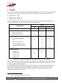
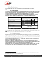
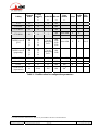
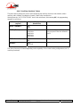
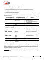
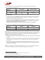
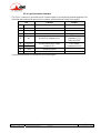
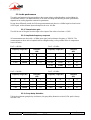
The following table shows the differences between the product versions. This manual describes all the
functions of the 20 kHz / 4B version, which is the most comprehensive.
Version
Characteristics 7 kHz 20 kHz / 2B 20 kHz / 4B
Number of S0 interfaces 1 1 2
Operation modes
Single wide band codec X X
Double codec, 7kHz X X X
Available algorithms
G711 (standard telephone) X X X
G722 X X X
MPEG Audio Layer II X X
4 sub-band ADPCM (mono) X X
4 sub-band ADPCM (stereo) X
TDAC option option
Available bit rates
64 kbit/s (1B) X X X
128 kbit/s (2B) X1 X X
192 kbit/s (3B) X
256 kbit/s (4B) X
Tableau 1 – Main characteristics of the three SCOOP 3 5AS versions
In the “double 7 kHz codec” mode, the equipment is equivalent to two independent mono codecs running
G711 or G722. Each mono codec can transmit, independently from the activity of the other codec, over a
B channel from the first ISDN interface.
One outstanding feature of the SCOOP 3 codec is the 5A System®: on receiving an incoming ISDN call,
the unit can automatically detect the coding algorithm and parameters of the calling codec, and then
adjust itself in a compatible configuration so that the connection succeeds regardless of the initial
configuration and that of the remote unit.
1 Two independent 64 kbit/s connections
® 5AS = Aeta Audio Advanced Automatic Adjustment System

2 SCOOP 3 5ASystem - User Manual 55 000 041 – Ed. D
This document is the property of AAS and can not be duplicated without authorisation January 2006 Scoop 3 5AS manual - Ed.D.doc
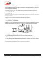
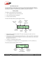
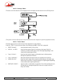
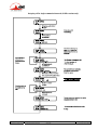
2. Functions
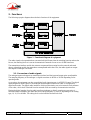
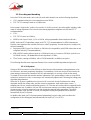
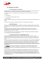
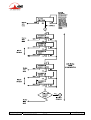
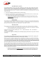
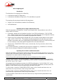
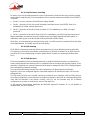
The following synoptic diagram shows the basic functions of the equipment.
Figure 1 - Functional diagram of equipment
The audio signals to be transmitted are converted to digital format, then the encoding function reduces the
bit rate, the resulting bit flow is sent to the transmission network via one or two S0 BRI interfaces.
The transmission interface module also extracts compressed data coming from the network and sends
them to a decoding module that reproduces uncompressed audio data. Last, the audio signals are output
after digital to analogue conversion.
2.1. Conversion of audio signals
The analogue inputs and outputs are transformer isolated, and the input and output gains are adjustable.
The sampling frequency of the analogue ⇔ digital converters is 48 kHz or 32 kHz depending on the
operating mode.
As an option, the equipment can also accept digital audio inputs/outputs, in AES/EBU format. The digital
inputs/outputs are used in place of the analogue inputs/outputs whenever the codec is configured for
digital audio mode. The digital audio interfaces can be synchronised or not to the internal clock reference
of the codec, which itself is derived from the network clock recovered by the transmission interface.
Having the digital samples from the audio interfaces (analogue or digital), sample rate conversion is
fulfilled whenever needed to get audio data at the coding frequency Fc which is, depending on the coding
type, 16, 24, 32 or 48 kHz. The coding clock is also locked to the network clock.

55 000 041 – Ed. D SCOOP 3 5ASystem - User Manual 3
This document is the property of AAS and can not be duplicated without authorisation January 2006 Scoop 3 5AS manual - Ed.D.doc
2.2. Encoding and decoding
In the dual 7 kHz codec mode, each codec (for each audio channel) can use the following algorithms:
• G711 (standard coding for voice transmission on the ISDN);
• ITU-T G722, running in mono at a 64 kbit/s rate.
In the normal “single codec” mode (only available on 20 kHz versions), the codec readily includes a wide
range of coding algorithms. First, one can select among algorithms compliant with ISO and ITU-T2
recommendations :
• G711;
• ITU-T G722 (mono at 64 kbit/s);
• MPEG Audio Layer II at 48, 32, 24 or 16 kHz, with programmable channel mode and bit rate ;
MPEG Audio and G722 algorithms comply with ITU-T J52 recommendation for ISDN transmission.
Besides, other algorithms are available, that are so-called “proprietary” because they do not comply with
enforced standards :
• Proprietary MPEG Layer II at 64 kbit/s or 128 kbit/s (for compatibility with ISDN codecs that are not
compliant with the J52 recommendation) ;
• 4SB ADPCM, running either in mono at a 128 kbit/s bit rate, or in stereo at 256 kbit/s (available on
20 kHz/4B version) ; the bandwidth with this algorithm is 15 kHz ;
• TDAC mono, running at 64 kbit/s, with a 15 kHz bandwidth ; available as an option.
The following describes some important features of the various available algorithms and protocols.
2.2.1. 5A System®
Setting an ISDN connection is often difficult, at least because of the numerous coding parameters to be
set. Moreover, with most proprietary algorithms, it is mandatory for the two devices to have exactly the
same settings, otherwise the connection will fail, and sometimes it is not easy to find out the reason.
5A stands for Aeta Audio Advanced Automatic Adjustment. This system makes it easier to set an ISDN
connection, because the codec, on receiving a call, automatically adjusts itself, following the calling party
algorithm and parameters.
When the 5A System is enabled on the unit and a call is received, the unit first detects the coding
algorithm used by the calling codec, and also senses its parameters: audio mode (mono, stereo…),
sampling rate, bit rate, inverse multiplexing protocol, etc. Then the unit can decode the compressed audio
from the remote unit. In addition, the unit will use these same settings for encoding and sending audio to
the remote unit, so that the remote unit can also decode the outgoing audio programme. The whole
process just takes a few seconds. Of course, all compatible coding configurations can be detected
automatically by the 5A System.
In double codec mode, the 5A System operates independently on each codec (each can detect the
configuration of the calling party and automatically set itself in G711 or G722).
2 former CCITT

4 SCOOP 3 5ASystem - User Manual 55 000 041 – Ed. D
This document is the property of AAS and can not be duplicated without authorisation January 2006 Scoop 3 5AS manual - Ed.D.doc
2.2.2. Notes about G711
G711 is the standard coding used for voice transmission on public telephone networks. This algorithm is
used for links (via ISDN) with telephones or hybrid devices.
2.2.3. Notes about G722
With G722 coding, three synchronisation modes are available:
• “Statistical recovery” byte synchronisation method (alias SRT) ;
• H221 synchronisation; in this case, 1.6 kbit/s from the compressed data are used for this;
• H221 synchronisation and H242 protocol.
H221 synchronisation is highly recommended when possible, as it features higher reliability and faster
recovery time, while degradation (because of the bit rate used for framing) is minimal.
H242 protocol is recommended by the ITU-T, and is included in J52. However, the mode with H221
synchronisation but without H242 protocol can be useful for compatibility with old generation codecs
which did not use this protocol.
2.2.4. Notes about J52 and MPEG coding
The ITU-T J52 recommendation was defined in order to allow the interoperability of various equipment
over the ISDN, using common coding standards. It includes the following features:
• Framing as per ITU-T H221 recommendation, ensuring byte synchronisation and interchannel
synchronisation when more than one 64 kbit/s B channel is required for the desired bit rate ;
• Interoperation procedures as per ITU-T H242 recommendation ;
• In the case of MPEG encoding, optional protection against transmission errors (Reed-Solomon error
correction codes).
Details about MPEG and J52 can be found in the annexes (refer to 6.1. Complements on the algorithms
and protocols used).
It must be noted that, thanks to the interoperation protocol, J52 codecs, when setting up a link, can
negotiate automatically and agree on a configuration that is compatible with the capability of both units
(regarding bit rate, channel mode, etc.). In this way, when the units differ in their capability (or make), the
resulting configuration may be different from expected beforehand, but in most cases the link will work
and audio will be transmitted.
As another useful consequence, this also gives users more tolerance to mistakes when configuring the
units on the two sides of the transmission links, as the codecs will adapt automatically even with
differences in the initial settings of the two units.
2.2.5. Notes about TDAC
As an option, the codec can also include the TDAC algorithm. TDAC is for Time Domain Aliasing
Cancellation ; this is a transform coding based on an MDCT (Modified Discrete Cosine Transform),
encoding a 15 kHz bandwidth mono signal at a 64 kbit/s bit rate.
Some specific product versions also include “asymmetric” modes:
• G722/TDAC : G722 encoding, TDAC decoding, running both in mono at 64 kbit/s ;
• TDAC/G722 : TDAC encoding, G722 decoding (with SRT), running both in mono at 64 kbit/s ; this
mode is symmetric to the previous one.

55 000 041 – Ed. D SCOOP 3 5ASystem - User Manual 5
This document is the property of AAS and can not be duplicated without authorisation January 2006 Scoop 3 5AS manual - Ed.D.doc
2.2.6. Symmetric or asymmetric codec modes
The codec allows two communication modes:
Symmetric communication: in this mode, the encoder and decoder both use the same coding algorithm
with the same configuration (channel mode, etc.). In this case, the communication is strictly symmetric
full-duplex, with exactly the same coding configuration used in both directions (local to remote and
remote to local). This is usually required when using proprietary algorithms.
Asymmetric communication: this mode is used for applications requiring different coding configurations
in the two directions. The J52 protocol allows such mode. To give some examples, it is possible to
transmit MPEG Layer II in one direction and Layer III in the other one, or MPEG stereo in one direction
and MPEG mono in the other one, or MPEG in one direction and G722 in the other one, etc.
Specific product versions also allow asymmetric modes wherein one direction is G722 coded while the
other one is TDAC coded. Such mode is useful e.g. in order to get a low delay return path encoded in
G722 while the send path is encoded with higher quality but a higher delay.
2.3. Transmission interface
The transmission interface includes one to three S0 BRI interfaces (depending on equipment version),
each allowing transmission over one or two 64 kbit/s B channels. Thus, the total available bit rate ranges
from 64 to 256 kbit/s (1 to 4 B channels).
In the dual 7 kHz codec mode, the equipment is equivalent to two mono codecs. Each mono codec can
transmit, independently from the activity of the other codec, over a B channel from the first S0 interface.
Only the first S0 interface is used in this configuration.
The codec synchronises itself onto the ISDN network clock when a link is active.
2.4. Supervision and user interface
These functional modules fulfil the control and supervision of the equipment (configuration,
communication management, status monitoring), thanks to a keyboard, an alphanumeric display, LED
indicators, and a remote control asynchronous serial interface.
The equipment also features a “Loop control” function: call set up and release can be remote controlled
with current loops and relays, instead of using for this the keyboard and/or the remote control port.
In order to allow easy and quick programming of the codec for specific operational configurations, the
equipment features fifty configuration memories (or “profiles”). When recalling a profile, the codec is
directly reconfigured with parameters that were stored beforehand in this profile by the operator.
Besides configuring the equipment operating mode, this module monitors its status (detection of alarm
conditions). On detecting operation or transmission faults, the equipment switches on indicators and relay
contacts. Three alarm classes are defined:
• “Major internal” alarm ; corresponds to a major fault internal to the equipment ;
• “Major external” alarm ; corresponds to a major fault whose origin is deemed external to the
equipment (for example, transmission fault);
• “Minor” alarm.

6 SCOOP 3 5ASystem - User Manual 55 000 041 – Ed. D
This document is the property of AAS and can not be duplicated without authorisation January 2006 Scoop 3 5AS manual - Ed.D.doc
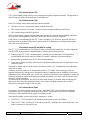
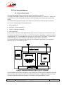
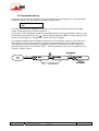
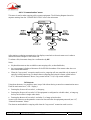
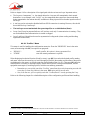
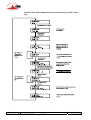
Besides, test loops can be activated:
• “AD/DA (or AES)” loop : uncompressed digital audio data are looped from output of
analogue → digital converter to input of digital → analogue converter ; if digital format (AES) is
selected, this loop redirects the digital audio input to the digital audio output ;
• Loop 3, or “Codec” loop : compressed audio data are looped just before the network interface ;
• Loop 2 : this loop sends the received data back to the network ; for the remote codec, the effect is the
same as a loop 3 when the transmission works correctly ;
• “Audio” loop (audio output to audio input) ; this allows the codec to send back to the remote codec
the signal it receives, after decoding then re-encoding.
The following drawing schematically shows the test loops:
2.5. Audio monitoring
This function enables the monitoring of the audio input (before encoding) or the audio output (after
decoding the received signal), and provides:
• A display of the signal level ;
• A test output on a stereo headphone jack.

55 000 041 – Ed. D SCOOP 3 5ASystem - User Manual 7
This document is the property of AAS and can not be duplicated without authorisation January 2006 Scoop 3 5AS manual - Ed.D.doc
2.6. Auxiliary functions
Note: in double codec mode, these functions are only available on codec 1 (or codec A).
2.6.1. Data channel
A bi-directional data channel can be transmitted along with the compressed audio signals, by reserving a
fraction of the transmitted bit rate. The equipment includes a serial asynchronous port for this purpose.
The data are transparently transmitted end-to-end; hardware signalling is not available.
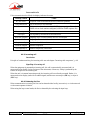
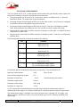
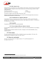
The interface speed is programmable at 300, 1200, 2400, 4800 or 9600 bauds. However, the actual
transmission capacity depends on the coding algorithm, as indicated by the table hereunder.
Possible transmission rate (bit/s)
Coding type
300 1200 2400 4800 9600
G722 (H221/H242)
MPEG Audio, J52
4SB ADPCM
TDAC3
G722 (SRT or H221)
Proprietary MPEG No data channel
Table 1 – Capacity of data channel depending on type of coding
Note: in double codec mode, the data channel is only available on codec 1 (or codec A), and only if this
codec runs G722 with H242 and 56 kbit/s allocated to the G722 audio signal.
2.6.2. Relay transmission
When this function is activated, the codec transmits to the remote unit the status of two isolated current
loops. The remote unit then opens or closes relay contacts according to the transmitted status. Conversely,
as the function is bi-directional, the codec activates its two relays (“dry” isolated contacts) depending on
the status of the two current loops on the remote unit.
A typical application is the transmission of an “on air” signal ; the contact closure may be used for e.g.
switching on a lamp or starting other devices.
When using J52 and MPEG coding, relay transmission can be activated along with other auxiliary
functions. For all the other algorithms, relay transmission is activated in place of the data channel (and it
is not available with G722 SRT or H221, proprietary MPEG or asymmetric TDAC).
In double codec mode, relay transmission is available in place of the data channel on codec 1 (or codec
A), and only if this codec runs G722 with H242 and 56 kbit/s allocated to the G722 audio signal.
3 In the particular case of the “asymmetric” TDAC modes, the data channel is unidirectional; data are transmitted only with the
TDAC encoded audio, not with the return G722 SRT encoded audio.

8 SCOOP 3 5ASystem - User Manual 55 000 041 – Ed. D
This document is the property of AAS and can not be duplicated without authorisation January 2006 Scoop 3 5AS manual - Ed.D.doc
2.6.3. Coordination channel
This function is available as an option. It enables the transmission of an auxiliary audio channel (or
coordination or “order-wire” channel), along with the compressed audio, by reserving 8 kbit/s from the
transmitted bit rate. This channel uses a compression algorithm of CELP-HLTP type.
This function is only available when the main audio programme is G722/H242, MPEG (J52) or ADPCM
encoded.
With G722/H242 or ADPCM, the coordination channel cannot be used along with other auxiliary
functions (i.e. data channel and relay transmission).
When using MPEG coding, all three auxiliary functions can be activated at the same time. Note that relay
transmission and the coordination channel are only compatible with AETA Audio products, as these
functions are not covered by the J52 recommendation.

55 000 041 – Ed. D SCOOP 3 5ASystem - User Manual 9
This document is the property of AAS and can not be duplicated without authorisation January 2006 Scoop 3 5AS manual - Ed.D.doc
3. Operation
3.1. General principles
The equipment control and supervision (configuration, status monitoring) is possible in two ways:
• “Local” mode: front panel keyboard and display, status indicators ;
• “Remote control” mode, thanks to an asynchronous serial port (or the optional Ethernet interface).
As a general rule, the configuration parameters are saved in non-volatile memory, and restored at power-
on.
Local mode operation is described in detail in chapter 4 (Detailed operating mode).
Thanks to the remote control mode, the codec can be operated from a computer with supervision
software. The supervision station is a PC computer running Windows, equipped with the TeleScoop™
configuration and monitoring software. This optional software gives full access to the codec functions
(configuration and status monitoring) with a graphical interface, and several units can be controlled from
the same computer.
Details about this supervision software can be found in the documentation and user manual of the
TeleScoop software.
For controlling connections in ISDN mode, it is also possible to use the “Loop control” function. When
this special connection mode is selected, one can trigger a call by activating an input current loop
(optically isolated), and release the line by de-activating this loop. In such case, an outgoing connection is
established or released only by this way, and no more from the front panel or the remote control interface
(however, all other parameters are still controlled from these interfaces as in the normal mode).
Besides, whatever the connection mode (normal or loop control), a “dry loop” is closed when an ISDN
connection is active.
The loop control interfaces are described in 3.2.2. and 5.1.10.

10 SCOOP 3 5ASystem - User Manual 55 000 041 – Ed. D
This document is the property of AAS and can not be duplicated without authorisation January 2006 Scoop 3 5AS manual - Ed.D.doc
3.2. Physical description of the equipment
The SCOOP 3 5ASystem codec is housed in a 19 inches chassis of 1U height (44 mm or 1.75”); it
includes a universal mains power supply.
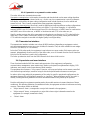
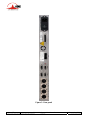
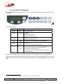
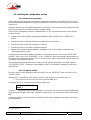
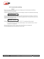
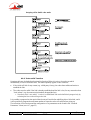
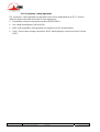
3.2.1. Front panel
All the elements needed for local control are on the front panel.
On the left-hand side, one can find a keyboard and a LCD display (described in chapter 4, dealing with
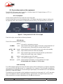
the operating mode), that are used for configuration and call set up. The right hand side is as follows:
Figure 2 - Front panel of SCOOP 3 5AS (right)
From left to right, one can find the following elements:
LED indicators
The 10 LEDs have the following meaning:
(amber) Only used for maintenance purposes
ALARM (red) Major internal alarm (power supply or fuse fault, wrong initialisation of
the microprocessors), detected by the network interface board.
± 12V, + 5V (green) Proper operation of power supply sources in the codec sub-assembly.
INT (red) Major internal alarm in the codec sub-assembly
EXT (red) Major external alarm (network clock fault, decoder synchronisation
failure, fault on AES input, codec “fallback”)
OVL (amber) Audio clipping on one of the inputs.
TEST (red) Test mode (the equipment is in a loopback mode)
DEC A, B (green) Proper operation of decoder A (or left), decoder B (or right).
In mono mode, only “decoder A” LED is active
Audio monitoring
Two LED bargraphs indicate the level of the audio signals, either at transmission or reception, depending
on the position of the Tx / Rx switch (Tx = transmission, Rx = reception). The 0 dB mark corresponds to
maximum level (or clipping level). For the analogue inputs/outputs, the maximum level is user adjustable
(see 4.4.11, “Audio I/O” Menu).
The signal can also be listened to with a headphone connected on the front panel (1/4” or 6.35 mm stereo
jack). The headphone volume is adjustable thanks to a potentiometer. The signal listened comes from
either transmission or reception depending on the Tx / Rx switch position.

55 000 041 – Ed. D SCOOP 3 5ASystem - User Manual 11
This document is the property of AAS and can not be duplicated without authorisation January 2006 Scoop 3 5AS manual - Ed.D.doc
Actions dealing with this area (connecting or disconnecting the jack, Tx/Rx selection, volume adjustment)
never affect the transmitted or received signals.
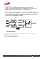
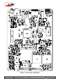
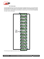
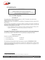
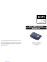
3.2.2. Rear panel
All connections are done on the rear panel of the codec. The characteristics of the interfaces and layout of
the sockets are detailed in chapter 5.1. Characteristics of interfaces.
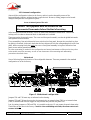
The following elements are available on the rear panel (refer to following Figure 3 - Rear panel):
Mains power socket
This is an IEC type power socket, including a power switch and one or two fuses depending on the
version.
Audio inputs/outputs
a) When using analogue inputs/outputs:
At the input, plug the audio cables into the female XLR sockets. At the output, plug the audio cables into
the male XLR sockets.
In mono mode, A channel only is used.
b) When using digital inputs/outputs:
For this mode, the same sockets are used as before. XLR sockets input A and (resp.) output A are used for
a digital input (mono or stereo) in AES/EBU format and (resp.) a digital output in AES/EBU format. The
XLR B sockets are not used.
ISDN - S0 (S/T) sockets
Two RJ45 sockets allow the connection to the ISDN. Their layout is standard. The sockets must be used
according to their number, i.e. #1 must be used if one line only is needed, #1 and #2 if two lines are
needed.
Remote control (Remote)
This 9-pin female sub-D socket is an asynchronous serial interface port, usable for remote controlling the
equipment thanks to a control and supervision PC.
Data
This 9-pin female sub-D socket is an asynchronous serial interface port, usable for transmission of a bi-
directional data channel (refer above to 2.6.1, Data channel).

12 SCOOP 3 5ASystem - User Manual 55 000 041 – Ed. D
This document is the property of AAS and can not be duplicated without authorisation January 2006 Scoop 3 5AS manual - Ed.D.doc
Figure 3 - Rear panel

55 000 041 – Ed. D SCOOP 3 5ASystem - User Manual 13
This document is the property of AAS and can not be duplicated without authorisation January 2006 Scoop 3 5AS manual - Ed.D.doc
Alarm indicators and contacts
The Alarm socket (9-pin female sub-D) is linked to two relays, providing isolated contacts, which are
closed in case of an alarm condition:
• Minor alarm contact (audio input overload) ;
• Major alarm (internal and external) contact; a red indicator (Al.) also indicates this relay is closed. By
internally configuring the equipment (jumpers on the motherboard), it is possible to program the
indicator and relay to react to only one type of major alarm (internal or external).
The pin-out of the socket and the detailed characteristics of the alarm relays can be found in chapter 5.1.6:
Alarm contacts (p. 56).
« AES / Sync » socket
This 9-pin female sub-D socket can be used in relation with the digital audio mode, when the digital
interface option is present on the equipment. The connector outputs clock and synchronisation signals,
that can be used for locking an external device:
• “Word Clock”, with a frequency FAES, sampling frequency of the AES input and output ;
• AES signal, derived from the same frequency FAES; this signal is identical to the AES output available
on output A when the digital audio format is selected.
« Aux. » socket
This 25-pin female sub-D socket groups the interfaces for the relay transmission function and the
(optional) coordination audio channel.
It also includes loop interfaces for the loop control function, as well as an (optional) isolated +5 V power
supply that can be used to provide current for the loop and relay interfaces.

14 SCOOP 3 5ASystem - User Manual 55 000 041 – Ed. D
This document is the property of AAS and can not be duplicated without authorisation January 2006 Scoop 3 5AS manual - Ed.D.doc
3.3. Equipment configuration parameters
The parameters may be divided into the following categories:
• Coding configuration parameters, which include audio coding type, coding frequency Fc (and
subsequently the nominal bandwidth), audio channel mode and transmission bit rate. Besides, in case
of MPEG coding, it is possible to select the error protection mode.
• Configuration of the audio interfaces, including: selection of analogue or digital format for the audio
interfaces, maximum level for the analogue inputs and outputs, and format of the AES/EBU
interfaces when digital format is selected.
• Parameters of the auxiliary functions: possible activation of a data channel, bit rate of this, possible
activation of the relay transmission, possible activation of the auxiliary audio channel (if this option is
available).
• Parameters of the network access: ISDN line numbers, network protocol version, etc.
• Parameters of the keyboard/display interface (as an example, selection of the language for the display
messages), parameters of the remote control port.
Chapter 4 (Detailed operating mode) describes these two last categories.
The parameters dealing with the audio interfaces are programmable independently from the others. On the
other hand, the auxiliary functions depend on the current coding type.
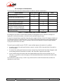
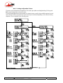
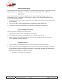
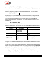
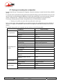
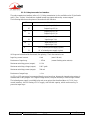
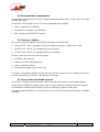
The following table is a summary, for each coding type, of the allowed values for the various parameters
of the coding configuration and auxiliary functions.
Meaning of abbreviations in the table:
• Channel mode : M = Mono, S = Stereo, JS = Joint stereo, DM = Dual Mono
• Coding : H242 = H242/H221 synchronisation, SRT = Statistical Recovery Timing
• X = function available with this type of coding
• FEC : Forward Error Correction = Reed-Solomon error correction
Only MPEG with J52 can be configured with all three auxiliary functions (data, auxiliary audio, relays).
For other algorithms, each function, when available, can only be used alone. Auxiliary functions are only
available for codec 1 when in double codec configuration.
In double codec mode (only available mode for the 7 kHz version), each audio channel can use one of the
configurations that are shaded in the table. Only codec 1 can then transmit a data channel or relays.

55 000 041 – Ed. D SCOOP 3 5ASystem - User Manual 15
This document is the property of AAS and can not be duplicated without authorisation January 2006 Scoop 3 5AS manual - Ed.D.doc
Coding Channel
mode
Coding
frequency
Fc Bandwidth Bit rate Data
channel Relays Audio
aux FEC
mode
kHz kHz kbit/s bit/s
G711 M 8 3.4 64k
G722 SRT M 16 7 64k
G722 H221 M 16 7 56k
56k 300 to 4800 X X
G722 H242 M 16 7 64k
MPEG Layer II
(J52)
M
DM
S
JS
16
24
32
48
7 to 20
depending
on Fc
64k
128k
192k
256k
300 to 9600 X X 0 to 3
MPEG Layer II
(proprietary)
M
DM
S
JS
16
24
32
48
7 to 20
depending
on Fc
64k
128k
4SB ADPCM M 32 15 128k 300 to 4800 X X
4SB ADPCM S 32 15 256k 300 to 4800 X X
TDAC M 32 15 64k 300 X
TDAC/G722
(asymmetric) M 32/16 15/7 64k
3004
Table 2 – Possible values for configuration parameters
4 The data channel is unidirectional ; data are only transmitted in the TDAC encoded direction.

16 SCOOP 3 5ASystem - User Manual 55 000 041 – Ed. D
This document is the property of AAS and can not be duplicated without authorisation January 2006 Scoop 3 5AS manual - Ed.D.doc
3.4. Installation and set up
3.4.1. Mounting and connections
Natural convection or forced air (A fan is switched on when the temperature exceeds a threshold) cools
the equipment. Do not obstruct the openings on the flanges and the rear panel.
To operate the codec, the minimum necessary connections to set up are (see details in the rear panel
description):
• Power supply ;
• Audio inputs and outputs (XLR sockets) ;
• S0 interface(s).
Whenever needed, the Alarm socket (alarm relay contacts) must be connected to an external supervision
system.
The pin out of the connectors is indicated in chapter 5.1: Characteristics of interfaces.
3.4.2. Initial set up
Before the first link, the equipment must be configured according to the desired operation mode (audio
input/output format, coding type and parameters, etc.) and the local conditions (ISDN numbers, network
protocol…).
For using the keyboard, a password may have to be entered. After factory setting or after total
configuration erasure, the password is blank (no password needed). Afterwards, a password can be
programmed by the user if one is needed.
For more details about the codec configuration, see chapter 3.3 (Equipment configuration parameters,
p. 14) and chapter 4 (Detailed operating mode).
3.4.3. Notes about the use of AES/EBU interfaces
When using digital audio interfaces, it must be decided whether the codec is “master” or “slave”
regarding audio sampling clock synchronisation. In the first case, the codec derives the sampling clock
from the network clock, and the device(s) connected to the codec must synchronise to the same clock
source.
The most common choice is rather the “slave” mode, to be used when it is not possible (or not desired) to
synchronise the external equipment onto the clock of the transmission link. In this case, the AES/EBU
interfaces should be set in the so-called “asynchronous” mode (wherein the AES interfaces are not
synchronous with the network clock). When in this mode, the codec derives the sampling clock of the
digital audio interfaces from its AES input, and sampling rate conversion (SRC) is used for interfacing to
the coding parts.
It is mandatory in such situation to provide the codec input with an AES signal featuring the same
sampling frequency as the external equipment, even if the codec is used only as a decoder. If this
requirement is ignored, the unit will exhibit unpredictable behaviour as it is left with a floating or wrong
reference clock.
If, on the contrary, it is decided to synchronise the external equipment (at 48 kHz or 32 kHz) onto the
transmission clock, the codec must be configured in “synchronous” mode. In this case, the output is
locked onto this clock, and it can be used as a reference to synchronise the equipment connected to the
codec output; the “Sync” socket also outputs separate signals for this purpose (see description in 3.2.2,
p. 13 and pinout in 5.1.9, p. 57). The digital audio signal at the codec input must then come from a device
synchronised by this way.
Page is loading ...
Page is loading ...
Page is loading ...
Page is loading ...
Page is loading ...
Page is loading ...
Page is loading ...
Page is loading ...
Page is loading ...
Page is loading ...
Page is loading ...
Page is loading ...
Page is loading ...
Page is loading ...
Page is loading ...
Page is loading ...
Page is loading ...
Page is loading ...
Page is loading ...
Page is loading ...
Page is loading ...
Page is loading ...
Page is loading ...
Page is loading ...
Page is loading ...
Page is loading ...
Page is loading ...
Page is loading ...
Page is loading ...
Page is loading ...
Page is loading ...
Page is loading ...
Page is loading ...
Page is loading ...
Page is loading ...
Page is loading ...
Page is loading ...
Page is loading ...
Page is loading ...
Page is loading ...
Page is loading ...
Page is loading ...
Page is loading ...
Page is loading ...
Page is loading ...
Page is loading ...
Page is loading ...
Page is loading ...
Page is loading ...
Page is loading ...
Page is loading ...
Page is loading ...
-
 1
1
-
 2
2
-
 3
3
-
 4
4
-
 5
5
-
 6
6
-
 7
7
-
 8
8
-
 9
9
-
 10
10
-
 11
11
-
 12
12
-
 13
13
-
 14
14
-
 15
15
-
 16
16
-
 17
17
-
 18
18
-
 19
19
-
 20
20
-
 21
21
-
 22
22
-
 23
23
-
 24
24
-
 25
25
-
 26
26
-
 27
27
-
 28
28
-
 29
29
-
 30
30
-
 31
31
-
 32
32
-
 33
33
-
 34
34
-
 35
35
-
 36
36
-
 37
37
-
 38
38
-
 39
39
-
 40
40
-
 41
41
-
 42
42
-
 43
43
-
 44
44
-
 45
45
-
 46
46
-
 47
47
-
 48
48
-
 49
49
-
 50
50
-
 51
51
-
 52
52
-
 53
53
-
 54
54
-
 55
55
-
 56
56
-
 57
57
-
 58
58
-
 59
59
-
 60
60
-
 61
61
-
 62
62
-
 63
63
-
 64
64
-
 65
65
-
 66
66
-
 67
67
-
 68
68
-
 69
69
-
 70
70
-
 71
71
-
 72
72


AETA SCOOP 3 5ASystem User manual
- Category
- Recording Equipment
- Type
- User manual
- This manual is also suitable for
Ask a question and I''ll find the answer in the document
Finding information in a document is now easier with AI
Related papers

Other documents
-
 Aeta Audio Systems Scoop Studio User manual
-
Crystal Vision ADCA402 User manual
-
 Telstra AETA Quick Installation Manual
-
 TANDBERG 5000 User manual
-
 TANDBERG Vision 5000 User manual
-
AVT MAGIC AE4 User manual
-
 Tieline Commander TLF200 Operating instructions
-
Unify Administration Manual OpenStage 5 OpenScape Voice User manual
-
Alcatel-Lucent OmniTouch 4135 IP Installation And Administration
-
Alcatel OmniTouch 4135 IP User guide


