VOLTCRAFT VC-10T Operating Instructions Manual
- Category
- Measuring & layout tools
- Type
- Operating Instructions Manual
This manual is also suitable for

D
BEDIENUNGSANLEITUNG SEITE 3 - 16
G
OPERATING INSTRUCTIONS PAGE 17 - 31
F
MODE D’EMPLOI PAGE 32 - 46
O
GEBRUIKSAANWIJZING PAGINA 47 - 61
Best.-Nr. / Item no. / N° de commande / Bestelnr.:
1298223 VC-10T 25 cm
1298224 VC-18T 45 cm
VERSION 03/15
Page is loading ...
Page is loading ...
Page is loading ...
Page is loading ...
Page is loading ...
Page is loading ...
Page is loading ...
Page is loading ...
Page is loading ...
Page is loading ...
Page is loading ...
Page is loading ...
Page is loading ...
Page is loading ...
Page is loading ...

G
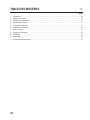
1. Introduction ......................................................................................................................................................... 19
2. Intended Use ..................................................................................................................................................... 20
3. Operating Elements ............................................................................................................................................ 21
4. Scope of Delivery ................................................................................................................................................ 21
5. Safety Information ............................................................................................................................................... 21
6. Indications and Symbols ..................................................................................................................................... 24
7. Commissioning ................................................................................................................................................... 25
8. Cleaning and Maintenance ................................................................................................................................. 29
9. Disposal .............................................................................................................................................................. 29
10. Troubleshooting .................................................................................................................................................. 30
11. Technical Data .................................................................................................................................................... 31

Dear customer,
Thank you for making the excellent decision to purchase this Voltcraft
®
product.
You have acquired a quality product from a brand family which has distinguished itself in the elds of measuring,
charging and grid technology thanks to its particular expertise and its continuous innovation.
With Voltcraft
®
, you will be able to handle difcult tasks, either as an ambitious hobbyist or as a professional user.
Voltcraft
®
offers reliable technology and a great price-performance-ratio.
We are positive: Starting to work with Voltcraft will also be the beginning of a long, successful relationship.
Enjoy your new Voltcraft
®
product!
International: www.conrad.com/contact
United Kingdom: www.conrad-electronic.co.uk/contact

The Flex current probe in connection with an alternate voltage meter (AC-V) permits measurement of the electrical
AC strength in an electrical conductor. The circuit does not have to be interrupted when applying the current probe
and during the measurements. The current probe works according to the Rogowsky principle and determines the
electrical eld that surrounds a conductor through which a current ows. An alternate voltage is output at the exit
that is proportional to the current strength.
The current probe has a protective isolation and can be used to measure isolated and unisolated electrical con-
ductors. At unisolated, actively dangerous conductors, the current probe must only be applied and accepted in the
powered-down circuit.
The voltage in the current measuring circuit against ground potential must not exceed 1,000 V in CAT III or 600 V
in CAT IV. Use of personal protection equipment is recommended for measurements in CAT III and CAT IV environ-
ments.
The connection to a voltage meter takes place via 4 mm safety plugs. They match most voltage meters.
The meter is operated with two conventional 1.5 V micro batteries (type AAA, LR03). The device must only be
operated with the specied battery type. Rechargeable batteries with a cell voltage of 1.2 V must not be used.
The meter must not be operated when it is open, i.e. with an open battery compartment or when the battery com-
partment cover is missing.
Measuring in potentially explosive areas (Ex) or damp rooms or under unfavourable ambient conditions is not
permitted. Unfavourable ambient conditions are: Moisture or high humidity, dust and ammable gases, fumes or
solvents, thunderstorms or thunderstorm conditions like strong electrostatic elds, etc.
For safety reasons, only use measuring lines or accessories which are adjusted to the specications of the meter
when measuring.
The meter must only be operated by persons who are familiar with the required provisions for the measurement and
the possible dangers. Use of personal protection equipment is recommended.
Any use other than that described above will lead to damage to the product and involves additional risks such as, for
example, short circuit, re, electric shock, etc. No part of this product must be modied or converted!
Read the operating instructions carefully and keep them for later reference.
Always observe the safety information!

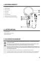
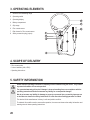
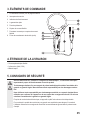
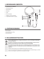
1 Switch for the measuring range
2 Operating switch
3 Operating display
4 Battery compartment
5 Grip range
6 Flex current sensor
7 Dial closure for Flex current sensor
8 Safety connection plug (output)
• Flex current probe
• 2 micro batteries (AAA, LR03)
• Operating instructions
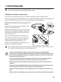
This device left the manufacturer’s factory in safe and perfect condition.
To maintain this condition and to ensure safe operation, the user must observe the safety information and
warning notes in these operating instructions.

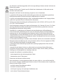
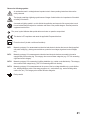
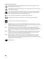
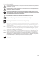
An exclamation mark in a triangle shows important notes in these operating instructions that must be
strictly observed.
The triangle containing a lightning symbol warns of danger of electrical shock or impairment of the electri-
cal safety of the device.
A crossed-out lighting symbol in a circle forbids the application and removal of the current probe to and
from unisolated, dangerously active conductors and warns of the possible dangers. Personal protection
equipment must be worn.
The „arrow“ symbol indicates that special advice and notes on operation are provided.
This device is CE-compliance and meets the applicable European directives
Protection class 2 (double or reinforced insulation)
Measuring category I for measurements at electrical and electronic devices that are not directly supplied
with mains voltage (e.g. battery-powered devices, protective low voltages, signal and control voltages,
etc.)
Measuring category II for measurements at electrical and electronic devices connected to the mains
supply directly with a mains plug. This category also covers all lower categories (e.g. CAT I for measuring
signal and control voltages).
Measuring category III for measuring in building installation (e.g. outlets or sub-distribution). This category
also covers all lower categories (e.g. CAT II for measuring electronic devices).
Measuring category IV for measurements at the source of the low-voltage installation (e.g. main distribu-
tion, building handover points of the energy suppliers, etc.), and outdoors (e.g. work at earthing cable,
outdoor line, etc.). This category also contains all lower categories.
Earth potential

For safety and approval reasons (CE), unauthorised conversion and/or modication of the device are not
permitted.
Consult an expert when in doubt as to the operation, the safety or the connection of the device.
Meters and accessories are not toys and have no place in the hands of children!
In commercial institutions, the accident prevention regulations of the Employer’s Liability Insurance As-
sociations for Electrical Systems and Operating Materials are to be observed.
In schools, training centres, computer and self-help workshops, handling of meters must be supervised
by trained personnel in a responsible manner.
The voltage between the meter and the earth potential must not exceed 1,000 V DC/AC in CAT III or 600
V DC/AC in CAT IV.
Be especially careful when dealing with voltages higher than 33 V alternate (AC) or >70 V direct voltage
(DC)! Even at these voltages it is possible to receive a potentially fatal electric shock if you touch electri-
cal conductors.
Check the meter and its measuring lines for damage before each measurement. Never carry out any
measurements if the protecting insulation is defective (torn, ripped off etc.). The rmly connected
measuring cables and the ex current sensor have a wear indicator. When they are damaged, a second
insulation layer in a different colour becomes visible. Damaged measuring lines cannot be replaced. The
measuring unit must no longer be used and must be replaced.
To avoid electric shock, do not to touch the connections/measuring points directly or indirectly during
measurements. Never reach beyond the indicated grip area (5) during measurements.
No voltage must be applied to connected measuring lines (8). They are pure measuring outputs.
Do not use the adapter just before, during or just after a thunderstorm (lightning!) / high-energy overvolt-
age!). Make sure that your hands, shoes, clothing, the oor, circuits and circuit components are dry.
Never operate the product in direct proximity of:
- strong magnetic or electromagnetic elds
- Transmitter aerials or HF generators.
This could affect the measurement.
If you have reason to assume that safe operation is no longer possible, disconnect the device imme-
diately and secure it against inadvertent operation. It can be assumed that safe operation is no longer
possible if:
- the device shows visible damage
- the device no longer functions
- the device was stored under unfavourable conditions over an extended period of time or
- following considerable stress during transportation.

Do not switch the device on immediately after taking it from a cold to a warm environment. The conden-
sation that forms might destroy your device. Allow the device to reach room temperature before switching
it on.
When performing measurements at power rails and unisolated conductors, be particularly careful - there
is a danger of electrical shock. Wear the corresponding protective equipment according to the respective
safety provisions (e.g. gloves, etc.) to avoid injury from electric shock and light arc, etc.
Do not leave packaging material unattended. It may become a dangerous toy for children.
Where possible, do not work alone to enable help.
Also observe the safety information in each chapter of these instructions.
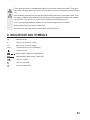
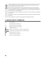
AC~ Alternate current
A Ampere (unit of electric current)
mV Milli-volt (unit of electric voltage)
mV/A Proportional ratio (mV per measured A)
Operating switch
Battery display “Battery full”; ashes slowly
Battery display “Battery empty”; ashes fast
Lock icon “Locked”
Lock icon “Unlocked”
Arrow for position mark

There may be transport protection caps in the safety plugs of the measuring lines. Remove them before
pushing the plugs into the meter sockets.
Before you can measure anything with the current probe, you have to insert the enclosed batteries.
The operating display (3) ashes slowly when the batteries (>2.5V) are full. If the operating display ashes quickly or
not at all, the batteries are at (<2.5 V) and must be replaced at once.
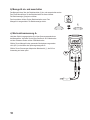
Disconnect the meter from any circuits and switch off the
device (OFF).
Unlock the battery compartment (4) counter-clockwise with
a small coin or a wide at-head screwdriver until the mark
points at the open lock symbol “Unlocked”.
Pull the battery compartment cover from the meter.
Insert two new batteries of the same type in the battery
compartment in the proper polarity. Observe the polarity
indications on the battery compartment cover (+ and -).
Close the battery compartment again carefully and lock it in
the reverse direction.
You can order suitable alkaline batteries stating the following order no.: Item no. 65 23 03 (please order two).
Use alkaline batteries since they offer high performance.

The meter can be switched on and off with the operating switch (2).
To switch on, push the operating switch until it latches. The operat-
ing display (3) starts to ash.
To switch off, push the operating switch again. The meter is off.
The operating display goes out.
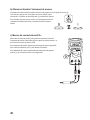
Connect the output plug (8) to the voltage measuring sockets of the meter.
Connect the red plug to the V-measuring socket and the black plug to the
COM measuring socket.
Select a matching alternate voltage range (AC-V) at the meter and switch on
the voltage meter.
Select the measuring range (1) at the current probe adapter that ts your
application best.

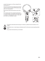
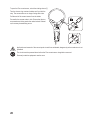
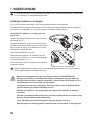
To open the Flex current sensor, unlock the rotating closure (7).
Turn the closure ring counter-clockwise until you feel the
stop. The arrow marks are no longer facing each other.
Pull the end of the current sensor from the holder.
Proceed in the reverse order to lock. Ensure that the two
arrow marks are facing each other when locked. Otherwi-
se, there may be measuring errors.
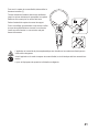
Application and removal of the current probe to and from unisolated, dangerously active conductors is not
permitted.
The circuit must be powered down before the Flex current sensor is applied or removed.
Personal protection equipment must be worn.

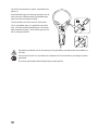
Always place the current sensor around only one
conductor, since the currents may otherwise cancel each
other out and wrong measured values may be displayed.
Never reach beyond the grip area (5) (marked with two
arrows in the sketch).
If current is owing in the conductor, the current can be
read at the meter.
The following alternate voltages are output proportionally
to the measured current:
30 A range 100 mV/A
300 A range 10 mV/A
3000 A range 1 mV/A
For a single- and three-phase connection able with a rmly installed mains plug, use the optional current
measuring adapters if required. They facilitate measurement at rmly connected mains cables.
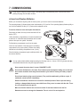
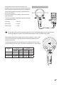
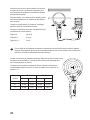
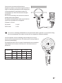
When reaching around the conductor, ensure that the conductor is at the centre
of the Flex current sensor. A deviating position increases the measuring error
(measuring deviation).
The following table shows the error tolerances to be added up and the corres-
ponding distances from the centre. The centre is marked with a “+” in the sketch.
Distance
eld
VC-10T VC-18T
Distance Error Distance Error
A 15 mm ±2% 35 mm ±1%
B 25 mm ±2.5% 50 mm ±1.5%
C 35 mm ±3% 60 mm ±2%

To ensure accuracy of the meter over an extended period of time, it should be calibrated once a year.
Apart from occasional cleaning and battery replacements, the meter requires no servicing.
Notes on replacing the battery are provided in chapter “7. Commissioning”.
Always observe the following safety information before cleaning the device:
Do not use any abrasive cleaning agents or petrol, alcohol or the like to clean the product. They will damage the
surface of the meter. Furthermore, the fumes are hazardous to your health and explosive. Also do not use any
sharp-edged tools, screwdrivers, metal brushes, etc. for cleaning.
Use a clean, lint-free, antistatic, slightly damp cloth for cleaning the device or the display or the measuring lines.
Allow the product to dry completely before you use it again to conduct measurements.
Old electronic devices are recyclable and should not be disposed of in household waste. At the end of its
service life, dispose of the product at the community collection point according to the relevant statutory
regulations. It is prohibited to dispose of the device in household waste.
You as the end user are required by law (Battery Ordinance) to return all used batteries/rechargeable
batteries. Disposing of them in the household waste is prohibited!
Batteries/rechargeable batteries containing toxic substances are marked with the symbols shown, which
indicate they cannot be disposed of in household waste. The descriptions for the respective heavy metals
are: Cd = cadmium, Hg = mercury, Pub = lead. You may return used batteries/rechargeable batteries free
of charge at the ofcial collection points of your community, in our stores, or wherever batteries/recharge-
able batteries are sold!
You thus full the legal requirements and make your contribution to protecting the environment!

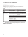
With this meter, you purchased a product built to the state of the art and operationally safe.
Nevertheless, problems or errors may occur.
For this reason, the following is a description of how you can easily remove possible malfunctions yourself:
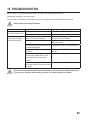
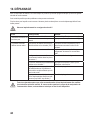
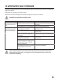
The meter does not work.
Are the batteries dead? Check the status. Replace the battery.
The meter is off. Push the operating switch (2).
The connected voltage
meter does not display
any measured values.
Is the wrong measuring function acti-
vated at the voltage meter (DC)?
Check the measuring function (AC) and
switch the function if required.
Is direct current measured? The Flex current probe can only measure
alternate current.
Are the measuring lines reliably inserted
in the measuring jacks?
Check the proper t of the measuring lines
Is the hold function at the voltage meter
activated?
Push the button "HOLD" to deactivate this
function.
Was a matching measuring range
chosen at the voltage meter or is the
resolution sufcient for the output
voltage.
Check the measuring range.
Is the measuring range of the Flex cur-
rent probe chosen incorrectly (too small/
too large)?
Check the measuring range.

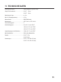
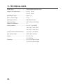
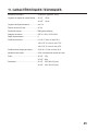
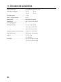
Voltage supply ..............................................2 micro batteries (type AAA, LR03)
Length of Flex current sensor ......................VC-10T 25 cm
......................................................................VC-18T 45 cm
Measuring line length ...................................approx. 2 m
Max. AC output voltage ...............................4.5 Vp
Measuring procedure ....................................RMS (effective value)
Measuring category ......................................CAT III 1000 V; CAT IV 600 V
Degree of contamination ..............................2
Working conditions ......................................0 to +30 °C, max. 80%rF
......................................................................+30 to +40 °C, max. 75%rF
......................................................................+40 to +50 °C, max. 45%rF
Storage conditions (without batteries) ..........-20 to +60 °C, max. 80%rF
Max. operating height ...................................2000 m above sea level
Weight ..........................................................VC-10T: 170 g
......................................................................VC-18T: 200 g
Dimensions ..................................................VC-10T: 120 x 280 x 25 (mm)
......................................................................VC-18T: 130 x 350 x 25 (mm)

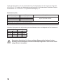
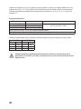
Indication of the accuracy in ± (% of the full measuring range). The accuracy is valid for one year at a temperature
of +23 °C ± 5 °C, and at a relative humidity of less than 80%, non-condensing. Additional temperature coefcient for
<18 °C and >28 °C: 0.2 x (specied accuracy)/1 °C
Measuring range Resolution Accuracy
3 - 30 A/AC 100 mV/A
±(3% of FS) for 45Hz - 500Hz30 - 300 A/AC 10 mV/A
300 - 3000 A/AC 1 mV/A
Noise level at the output: < 8 mV for all measuring ranges
The accuracies apply to 10% to 100 % of the measuring ranges.
Additional error limits at deviation of the current-conducting conductor from the centre of the Flex current sensor:
VC-10T VC-18T
Distance Error Distance Error
15 mm ±2% 35 mm ±1%
25 mm ±2.5% 50 mm ±1.5%
35 mm ±3% 60 mm ±2%
Page is loading ...
Page is loading ...
Page is loading ...
Page is loading ...
Page is loading ...
Page is loading ...
Page is loading ...
Page is loading ...
Page is loading ...
Page is loading ...
Page is loading ...
Page is loading ...
Page is loading ...
Page is loading ...
Page is loading ...
Page is loading ...
Page is loading ...
Page is loading ...
Page is loading ...
Page is loading ...
Page is loading ...
Page is loading ...
Page is loading ...
Page is loading ...
Page is loading ...
Page is loading ...
Page is loading ...
Page is loading ...
Page is loading ...
Page is loading ...
Page is loading ...
Page is loading ...

D
Impressum
Dies ist eine Publikation der Conrad Electronic SE, Klaus-Conrad-Str. 1, D-92240 Hirschau (www.conrad.com).
Alle Rechte einschließlich Übersetzung vorbehalten. Reproduktionen jeder Art, z. B. Fotokopie, Mikroverlmung, oder die
Erfassung in elektronischen Datenverarbeitungsanlagen, bedürfen der schriftlichen Genehmigung des Herausgebers.
Nachdruck, auch auszugsweise, verboten. Die Publikation entspricht dem technischen Stand bei Drucklegung.
© Copyright 2015 by Conrad Electronic SE.
G
Legal Notice
This is a publication by Conrad Electronic SE, Klaus-Conrad-Str. 1, D-92240 Hirschau (www.conrad.com).
All rights including translation reserved. Reproduction by any method, e.g. photocopy, microlming, or the capture in elec-
tronic data processing systems require the prior written approval by the editor. Reprinting, also in part, is prohibited. This
publication represent the technical status at the time of printing.
© Copyright 2015 by Conrad Electronic SE.
F
Information légales
Ceci est une publication de Conrad Electronic SE, Klaus-Conrad-Str. 1, D-92240 Hirschau (www.conrad.com).
Tous droits réservés, y compris de traduction. Toute reproduction, quelle qu‘elle soit (p. ex. photocopie, microlm, saisie
dans des installations de traitement de données) nécessite une autorisation écrite de l‘éditeur. Il est interdit de le réimpri-
mer, même par extraits. Cette publication correspond au niveau technique du moment de la mise sous presse.
© Copyright 2015 by Conrad Electronic SE.
O
Colofon
Dit is een publicatie van Conrad Electronic SE, Klaus-Conrad-Str. 1, D-92240 Hirschau (www.conrad.com).
Alle rechten, vertaling inbegrepen, voorbehouden. Reproducties van welke aard dan ook, bijvoorbeeld fotokopie, micro-
verlming of de registratie in elektronische gegevensverwerkingsapparatuur, vereisen de schriftelijke toestemming van de
uitgever. Nadruk, ook van uittreksels, verboden. De publicatie voldoet aan de technische stand bij het in druk bezorgen.
© Copyright 2015 by Conrad Electronic SE. V2_0315_02/VTP
-
 1
1
-
 2
2
-
 3
3
-
 4
4
-
 5
5
-
 6
6
-
 7
7
-
 8
8
-
 9
9
-
 10
10
-
 11
11
-
 12
12
-
 13
13
-
 14
14
-
 15
15
-
 16
16
-
 17
17
-
 18
18
-
 19
19
-
 20
20
-
 21
21
-
 22
22
-
 23
23
-
 24
24
-
 25
25
-
 26
26
-
 27
27
-
 28
28
-
 29
29
-
 30
30
-
 31
31
-
 32
32
-
 33
33
-
 34
34
-
 35
35
-
 36
36
-
 37
37
-
 38
38
-
 39
39
-
 40
40
-
 41
41
-
 42
42
-
 43
43
-
 44
44
-
 45
45
-
 46
46
-
 47
47
-
 48
48
-
 49
49
-
 50
50
-
 51
51
-
 52
52
-
 53
53
-
 54
54
-
 55
55
-
 56
56
-
 57
57
-
 58
58
-
 59
59
-
 60
60
-
 61
61
-
 62
62
-
 63
63
-
 64
64


VOLTCRAFT VC-10T Operating Instructions Manual
- Category
- Measuring & layout tools
- Type
- Operating Instructions Manual
- This manual is also suitable for
Ask a question and I''ll find the answer in the document
Finding information in a document is now easier with AI
in other languages
- français: VOLTCRAFT VC-10T
- Deutsch: VOLTCRAFT VC-10T
- Nederlands: VOLTCRAFT VC-10T
Related papers
-
VOLTCRAFT VC135 Safety Instructions
-
VOLTCRAFT VC-7055BT User manual
-
-
-
-
-
-
-
-
Other documents
-
ROSIERES RBP 160 User manual
-
 Reely 1877013 Operating instructions
-
BOMANN KB 3713 Owner's manual
-
 Reely 1877012 Operating instructions
-
Optimus PU-10T User manual
-
GMC G-TARM120 Owner's manual
-
Gossen MetraWatt Telearm 180 Operating instructions
-
Makita LD060P Owner's manual
-
Dolmar MM-100 Owner's manual
-
Zenner WPVR/WPVRE Installation guide

